

DataDirect Networks StorageScaler 8460 User Manual
StorageScaler 8460
User Guide
SS8460
Document No.: 96-30052-001
Revision: A4

Important Information
Information in this document is subject to change without notice and does not represent a commitment
on the part of DataDirect Networks, Inc. No part of this manual may be reproduced or transmitted in any
form or by any means, electronic or mechanical, including photocopying and recording, for any purpose
other than the purchaser’s personal use without the written permission of DataDirect Networks, Inc.
© 2014 DataDirect Networks, Inc. All rights reserved.
DataDirect Networks, the DataDirect Networks logo, DirectOS, DirectProtect, DirectMon, EXAScaler,
GRIDScaler, Information in Motion, NAS Scaler, NoFS, ObjectAssure, SATAssure, Silicon Storage
Appliance, S2A, Storage Fusion Architecture, SFA, Storage Fusion Fabric, Storage Fusion Xcelerator,
SFX, xSTREAMScaler, Web Object Scaler, WOS are registered trademarks or trademarks of DataDirect
Networks, Inc. All other brand and product names are trademarks of their respective holders.
DataDirect Networks makes no warranties, express or implied, including without limitation the implied
warranties of merchantability and fitness for a particular purpose of any products or software.
DataDirect Networks does not warrant, guarantee or make any representations regarding the use or the
results of the use of any products or software in terms of correctness, accuracy, reliability, or otherwise.
The entire risk as to the results and performance of the product and software are assumed by you. The
exclusion of implied warranties is not permitted by some jurisdictions; this exclusion may not apply to
you.
In no event will DataDirect Network, their directors, officers, employees, or agents (collectively
DataDirect Networks) be liable to you for any consequential, incidental, or indirect damages, including
damages for loss of business profits, business interruption, loss of business information, and the like,
arising out of the use or inability to use any DataDirect product or software even if DataDirect Networks
has been advised of the possibility of such damages by you. Because some jurisdictions do not allow the
exclusion or limitation of liability for consequential or incidental damages, these limitations may not
apply to you. DataDirect Networks liability to you for actual damages from any cause whatsoever, and
regardless of the form of the action (whether in contract, tort including negligence, product liability or
otherwise), is limited to the sum you paid for the DataDirect product or software.
August 2014
96-30052-001 Rev. A4 DataDirect Networks StorageScaler 8460 User Guide | 2

Important Information
STANDARD WARRANTY
Definitions: This two-year limited warranty applies to the following DataDirect Networks network infrastructure
and individual SAN solution components that include: Silicon Storage Appliance Hardware, Drive Modules, RAID
Hardware Components, Storage Hardware Components, and Disk Drive Docking Bays and Enclosures (hereinafter
“DataDirect Networks Products”). Fibre Channel Interface Kits, SCSI Interface Kits, Host Adapters and Networking
Products are limited to a 90-day warranty. Software bundled or included with DataDirect Networks solutions are
furnished exclusively under the terms of the applicable license agreements.
Warranty: DataDirect Networks warrants that the DataDirect Networks Products accompanied by this limited
Warranty are free from defects in material and workmanship for a period of two years from the date of original
purchase from DataDirect Networks or an authorized DataDirect Networks reseller. During the term of this
Warranty, DataDirect Networks will, at its option, repair or replace any defective parts of the DataDirect Networks
products purchased under this Warranty at no additional charge. Repair parts or replacement DataDirect Networks
products will be furnished on an exchange basis, and will be either reconditioned or new. When returning the
DataDirect Networks products, the Purchaser must prepay any shipping charges. In addition, the Purchaser is
responsible for insuring the products returned and assumes the risk of loss during shipment.
Warranty Claim Requirements: Purchaser claims made pursuant to this Warranty must conform to the following
requirements:
1. The DataDirect Networks products must be returned to (a) an Authorized DataDirect Networks Servicing Reseller
in the country of original purchase, or (b) a DataDirect Networks facility which performs Warranty service in the
country of original purchase, or (c) an Authorized DataDirect Networks Third Party Service Provider in the
country of original purchase.
2. The Purchaser must provide proof of purchase and date of purchase from DataDirect Networks or an Authorized
DataDirect Networks Reseller.
3. The Purchaser may request information on how to obtain warranty service by contacting any Authorized
DataDirect Networks Reseller, or by writing to the Warranty Service Department, DataDirect Networks, 9351
Deering Avenue, Chatsworth, CA 91311.
Disclaimers: THIS LIMITED WARRANTY DOES NOT APPLY TO ANY DATADIRECT NETWORKS PRODUCTS
WHICH HAVE BEEN DAMAGED OR RENDERED DEFECTIVE (a) AS A RESULT OF ACCIDENT, MISUSE, OR
ABUSE; (b) BY THE USE OF PARTS NOT MANUFACTURED OR SOLD BY DATADIRECT NETWORKS; (c) BY
MODIFICATION WITHOUT THE WRITTEN PERMISSION OF DATADIRECT NETWORKS, OR (d) AS A RESULT OF
SERVICE BY ANYONE OTHER THAN DATADIRECT NETWORKS, AN AUTHORIZED DATADIRECT NETWORKS
SERVICING RESELLER, OR AN AUTHORIZED DATADIRECT NETWORKS THIRD PARTY SERVICE PROVIDER.
EXCEPT AS EXPRESSLY SET FORTH ABOVE, DATADIRECT NETWORKS MAKES NO OTHER WARRANTIES,
EXPRESS OR IMPLIED, INCLUDING, BUT NOT LIMITED TO, ANY IMPLIED WARRANTIES OF
MERCHANTABILITY AND FITNESS FOR PURPOSE, AND DATADIRECT NETWORKS EXPRESSLY DISCLAIMS
ALL WARRANTIES NOT STATED HEREIN. IN THE EVENT THE PRODUCTS ARE NOT FREE FROM DEFECTS AS
WARRANTED ABOVE, THE PURCHASER'S SOLE REMEDY SHALL BE REPAIR OR REPLACEMENT AS
PROVIDED ABOVE. UNDER NO CIRCUMSTANCES WILL DATADIRECT NETWORKS BE LIABLE TO THE
PURCHASER, OR TO ANY USER, FOR ANY DAMAGES, EXPENSES, LOST PROFITS, LOST SAVINGS, DAMAGE TO
OR REPLACEMENT OF EQUIPMENT AND PROPERTY, COSTS OF RECOVERING, REPROGRAMMING, OR
REPRODUCING ANY PROGRAM OR DATA STORED IN OR USED WITH THE PRODUCTS, OR OTHER DAMAGES
ARISING OUT OF THE USE OR INABILITY TO USE THE DATADIRECT NETWORKS PRODUCTS.
ANY IMPLIED WARRANTIES ARE LIMITED TO THE TERMS OF THIS EXPRESS LIMITED WARRANTY. SOME
STATES DO NOT ALLOW THE EXCLUSION OR LIMITATION OF INCIDENTAL OR CONSEQUENTIAL DAMAGES
FOR CONSUMER PRODUCTS, AND SOME STATES DO NOT ALLOW LIMITATIONS ON HOW LONG AN IMPLIED
WARRANTY LASTS, SO THE ABOVE LIMITATIONS OR EXCLUSIONS MAY NOT APPLY TO YOU. THIS WARRANTY
GIVES YOU SPECIFIC LEGAL RIGHTS, AND YOU MAY ALSO HAVE OTHER RIGHTS WHICH VARY FROM STATE
TO STATE.
96-30052-001 Rev. A4 DataDirect Networks StorageScaler 8460 User Guide | 3

Preface
What is in this guide
This user guide contains information regarding features and functions of the DataDirect
Networks StorageScaler 8460. It also gives you step-by-step instructions on how to
install the disk enclosure and how to maintain the enclosure.
Potential for Radio Frequency Interference
USA Federal Communications Commission (FCC)
This equipment has been tested and found to comply with the limits for a class A digital
device, pursuant to Part 15 of the FCC rules. These limits are designed to provide
reasonable protection against harmful interference when the equipment is operated in a
commercial environment. This equipment generates, uses and can radiate radio
frequency energy and, if not installed and used in accordance with the instruction
manual, may cause harmful interference to radio communications. Operation of this
equipment in a residential area is likely to cause harmful interference in which case the
user will be required to correct the interference at his own expense.
Properly shielded and grounded cables and connectors must be used in order to meet
FCC emission limits. The supplier is not responsible for any radio or television
interference caused by using other than recommended cables and connectors or by
unauthorized changes or modifications to this equipment. Unauthorized changes or
modifications could void the user’s authority to operate the equipment.
This device complies with Part 15 of the FCC Rules. Operation is subject to the following
two conditions: (1) this device may not cause harmful interference, and (2) this device
must accept any interference received, including interference that may cause undesired
operation.
European Regulations
This equipment complies with European Regulations EN 55022 Class A: Limits and
Methods of Measurement of Radio Disturbance Characteristics of Information
Technology Equipments and EN50082-1: Generic Immunity.
Canadian Regulations
ICES-003 Class A Notice - Avis NMB-003, Classe A
This Class A digital apparatus complies with Canadian ICES-003.
Cet appareil numérique de la classe A est conforme à la norme NMB-003 du Canada.
Safe Handling
• Remove disk modules to minimize weight
• Do not try to lift the enclosure by yourself
96-30052-001 Rev. A4 DataDirect Networks StorageScaler 8460 User Guide | 4
Safety
Preface
NOTE :
Warning
CAUTION !
• Plug-in modules are part of the enclosure and must only be removed when a
replacement can be immediately installed. Operation of the SS8460 with ANY
modules missing will disrupt the airflow and the components will not receive
sufficient cooling.
• In order to comply with applicable safety, emission, and thermal requirements, the
top cover should remain closed while running.
• The SS8460 system must only be operated from a power supply input voltage
range of 200VAC to 264VAC.
If this equipment is used in a manner not specified by the
manufacturer, the protection provided by the equipment may be
impaired.
The SS8460 MUST be grounded before applying power. Unplug the
!
unit if you think that it has become damaged in any way and before
you move it.
To maintain proper airflow through the system, operate the
system with the enclosure top cover closed.
NOTE :
• The equipment is intended to operate with two (2) working power and cooling
modules (PCM). Before removal/replacement of any module, disconnect all
supply power for complete isolation.
• A faulty PCM must be replaced with a fully operational module within 24 hours.
• Do not remove a faulty PCM unless you have a replacement module of the correct
type ready for insertion.
• A safe electrical earth connection must be provided to the power cord.
• Provide a suitable power source with electrical overload protection to meet the
requirements given in the product specifications.
On racked systems, the operational voltage range will be limited to
200-240V nominal to reduce the current within the power
distribution system.
To minimize the risk of electric shock, disconnect the power from
the PCM, either by turning off the switch or by physically removing
the power cable, prior to removing the PCM from the enclosure.
96-30052-001 Rev. A4 DataDirect Networks StorageScaler 8460 User Guide | 5
Preface
• There are no user-replaceable parts inside the PCM. Do not attempt to repair a
PCM. Disassemble of a PCM voids the warranty.
!
Warning
Due to the danger of electrical shock, do not remove covers from the
PCM. Return the module to your supplier for repair.
Recycling of Waste Electrical and Electronic Equipment (WEEE)
At the end of the product’s life, all scrap/ waste electrical and electronic equipment
should be recycled in accordance with local/national regulations applicable to the
handling of hazardous/toxic electrical and electronic waste materials.
NOTE :
Observe all applicable safety precautions, such as weight restrictions,
handling batteries, and lasers, detailed in the preceding paragraphs
when dismantling and disposing of this equipment.
ESD Precautions
CAUTION !
Observe all conventional ESD precautions when handling the
SS8460 plug-in modules and components. Avoid contact with
backplane components and module connectors.
Data Security
• Each enclosure contains up to 84 removable disk drive modules. Disk units are
fragile. Handle them with care, and keep them away from strong magnetic fields.
• Always allow new disks to acclimate to room temperature (for 1 to 2 hours) prior
to installation.
• ALL the supplied plug-in modules and required blank modules must be in place for
the air to flow correctly around the enclosure and also to complete the internal
circuitry.
• If the enclosure is used with modules or blanking plates missing for more than a few
minutes, the enclosure can overheat, causing power failure and data loss. Such use
may also invalidate the warranty.
• If you remove a disk module, replace it immediately. If it is faulty, replace it with a
disk module of the same type and capacity.
• Ensure that all disk drives are removed from the enclosure before attempting to
move the rack installation.
• Do not abandon your backup routines. No system is completely foolproof.
96-30052-001 Rev. A4 DataDirect Networks StorageScaler 8460 User Guide | 6

Table of Contents
Preface Potential for Radio Frequency Interference. . . . . . . . . . . . . . . . . . . . . . . . . . . . . . . . . . . . . . . . . . 4
European Regulations . . . . . . . . . . . . . . . . . . . . . . . . . . . . . . . . . . . . . . . . . . . . . . . . . . . . . . . . . . . . . . . . 4
Canadian Regulations . . . . . . . . . . . . . . . . . . . . . . . . . . . . . . . . . . . . . . . . . . . . . . . . . . . . . . . . . . . . . . . . 4
Safe Handling . . . . . . . . . . . . . . . . . . . . . . . . . . . . . . . . . . . . . . . . . . . . . . . . . . . . . . . . . . . . . . . . . . . . . . . . . 4
Safety. . . . . . . . . . . . . . . . . . . . . . . . . . . . . . . . . . . . . . . . . . . . . . . . . . . . . . . . . . . . . . . . . . . . . . . . . . . . . . . . . . 5
Recycling of Waste Electrical and Electronic Equipment (WEEE). . . . . . . . . . . . . . . . . . . . 6
ESD Precautions . . . . . . . . . . . . . . . . . . . . . . . . . . . . . . . . . . . . . . . . . . . . . . . . . . . . . . . . . . . . . . . . . . . . . . 6
Data Security. . . . . . . . . . . . . . . . . . . . . . . . . . . . . . . . . . . . . . . . . . . . . . . . . . . . . . . . . . . . . . . . . . . . . . . . . . 6
Chapter 1
Introduction
Chapter 2
Installation
1.1 The StorageScaler 8460 System Overview . . . . . . . . . . . . . . . . . . . . . . . . . . . . . . 10
1.2 Enclosure Chassis. . . . . . . . . . . . . . . . . . . . . . . . . . . . . . . . . . . . . . . . . . . . . . . . . . . . . . . . . 11
1.3 I/O Module . . . . . . . . . . . . . . . . . . . . . . . . . . . . . . . . . . . . . . . . . . . . . . . . . . . . . . . . . . . . . . . 12
1.4 Power and Cooling Module. . . . . . . . . . . . . . . . . . . . . . . . . . . . . . . . . . . . . . . . . . . . . . 13
1.5 5V Regulator. . . . . . . . . . . . . . . . . . . . . . . . . . . . . . . . . . . . . . . . . . . . . . . . . . . . . . . . . . . . . . 13
1.6 Disk Modules . . . . . . . . . . . . . . . . . . . . . . . . . . . . . . . . . . . . . . . . . . . . . . . . . . . . . . . . . . . . . 14
2.1 Installation Overview. . . . . . . . . . . . . . . . . . . . . . . . . . . . . . . . . . . . . . . . . . . . . . . . . . . . . 16
2.2 Unpacking the SS8460 . . . . . . . . . . . . . . . . . . . . . . . . . . . . . . . . . . . . . . . . . . . . . . . . . . . 17
2.2.1 Racked System . . . . . . . . . . . . . . . . . . . . . . . . . . . . . . . . . . . . . . . . . . . . . . . . . . . 17
2.2.2 Packing List. . . . . . . . . . . . . . . . . . . . . . . . . . . . . . . . . . . . . . . . . . . . . . . . . . . . . . . 17
2.3 Installing the SS8460 in a Rack. . . . . . . . . . . . . . . . . . . . . . . . . . . . . . . . . . . . . . . . . . . 19
2.4 Installing Cable Management Assembly . . . . . . . . . . . . . . . . . . . . . . . . . . . . . . . . 25
2.4.1 Insert Cables into Baskets . . . . . . . . . . . . . . . . . . . . . . . . . . . . . . . . . . . . . . . . . 25
2.4.2 Attach CMAs to Rack Rails . . . . . . . . . . . . . . . . . . . . . . . . . . . . . . . . . . . . . . . . . 26
2.5 Cable Connections . . . . . . . . . . . . . . . . . . . . . . . . . . . . . . . . . . . . . . . . . . . . . . . . . . . . . . . 28
2.6 Disk Module Installation . . . . . . . . . . . . . . . . . . . . . . . . . . . . . . . . . . . . . . . . . . . . . . . . . 29
2.6.1 Blank Module Requirement . . . . . . . . . . . . . . . . . . . . . . . . . . . . . . . . . . . . . . . 30
2.6.2 Procedure . . . . . . . . . . . . . . . . . . . . . . . . . . . . . . . . . . . . . . . . . . . . . . . . . . . . . . . . 30
2.7 Powering Up the SS8460. . . . . . . . . . . . . . . . . . . . . . . . . . . . . . . . . . . . . . . . . . . . . . . . . 31
2.7.1 Power Connections . . . . . . . . . . . . . . . . . . . . . . . . . . . . . . . . . . . . . . . . . . . . . . . 32
2.7.2 Single SS8460 Power Up Procedure . . . . . . . . . . . . . . . . . . . . . . . . . . . . . . . 32
2.7.2.1 Power Down Procedure . . . . . . . . . . . . . . . . . . . . . . . . . . . . . . . . . . . . . . . . . . . . . . 32
2.7.3 Multiple SS8460 Power Up Procedure . . . . . . . . . . . . . . . . . . . . . . . . . . . . . 32
2.7.3.1 Power Down Procedure . . . . . . . . . . . . . . . . . . . . . . . . . . . . . . . . . . . . . . . . . . . . . . 33
Chapter 3
Maintenance
96-30052-001 Rev. A4 DataDirect Networks StorageScaler 8460 User Guide | 7
3.1 Monitoring the SS8460. . . . . . . . . . . . . . . . . . . . . . . . . . . . . . . . . . . . . . . . . . . . . . . . . . . 35
3.1.1 LCD Module . . . . . . . . . . . . . . . . . . . . . . . . . . . . . . . . . . . . . . . . . . . . . . . . . . . . . . 35
3.1.2 Enclosure Status LEDs. . . . . . . . . . . . . . . . . . . . . . . . . . . . . . . . . . . . . . . . . . . . . 36
3.1.3 Disk Locate and Status LEDs. . . . . . . . . . . . . . . . . . . . . . . . . . . . . . . . . . . . . . . 37
3.1.3.1 Disk Activity LEDs. . . . . . . . . . . . . . . . . . . . . . . . . . . . . . . . . . . . . . . . . . . . . . . . . . . . . 37
3.1.4 I/O Module LEDs . . . . . . . . . . . . . . . . . . . . . . . . . . . . . . . . . . . . . . . . . . . . . . . . . . 38
3.1.5 Power and Cooling Module LEDs . . . . . . . . . . . . . . . . . . . . . . . . . . . . . . . . . . 39

Table of Contents
3.1.6 5V Regulator LEDs . . . . . . . . . . . . . . . . . . . . . . . . . . . . . . . . . . . . . . . . . . . . . . . . 40
3.1.7 Audible Alarm Tone Patterns . . . . . . . . . . . . . . . . . . . . . . . . . . . . . . . . . . . . . . 40
3.1.8 Temperature Sensor Locations . . . . . . . . . . . . . . . . . . . . . . . . . . . . . . . . . . . . 41
3.2 Component Failure Recovery . . . . . . . . . . . . . . . . . . . . . . . . . . . . . . . . . . . . . . . . . . . . 42
3.2.1 Replacing a Power and Cooling Module . . . . . . . . . . . . . . . . . . . . . . . . . . . 43
3.2.2 Replacing an I/O Module . . . . . . . . . . . . . . . . . . . . . . . . . . . . . . . . . . . . . . . . . . 44
3.2.3 Replacing a Disk Module . . . . . . . . . . . . . . . . . . . . . . . . . . . . . . . . . . . . . . . . . . 45
3.2.4 Replacing a 5V Regulator. . . . . . . . . . . . . . . . . . . . . . . . . . . . . . . . . . . . . . . . . . 46
3.2.5 Replacing a LCD Module . . . . . . . . . . . . . . . . . . . . . . . . . . . . . . . . . . . . . . . . . . 47
Appendix A Product Specifications . . . . . . . . . . . . . . . . . . . . . . . . . . . . . . . . . . . . . . . . . . . . . . . . . . . . . . . . . . . . . . 48
A.1 General Specifications . . . . . . . . . . . . . . . . . . . . . . . . . . . . . . . . . . . . . . . . . . . . . . . . . . . 49
A.2 Power & Cooling Module AC Input Specifications . . . . . . . . . . . . . . . . . . . . . . 49
A.3 Power & Cooling Module DC Output Specifications . . . . . . . . . . . . . . . . . . . . 50
A.4 RoHS Compliance . . . . . . . . . . . . . . . . . . . . . . . . . . . . . . . . . . . . . . . . . . . . . . . . . . . . . . . . 50
A.5 Temperature, Humidity, and Altitude . . . . . . . . . . . . . . . . . . . . . . . . . . . . . . . . . . . 51
A.6 Shock and Vibration. . . . . . . . . . . . . . . . . . . . . . . . . . . . . . . . . . . . . . . . . . . . . . . . . . . . . . 51
A.7 Rotational Vibration. . . . . . . . . . . . . . . . . . . . . . . . . . . . . . . . . . . . . . . . . . . . . . . . . . . . . . 51
A.8 Packaging and Transportation. . . . . . . . . . . . . . . . . . . . . . . . . . . . . . . . . . . . . . . . . . . 52
A.9 Acoustics . . . . . . . . . . . . . . . . . . . . . . . . . . . . . . . . . . . . . . . . . . . . . . . . . . . . . . . . . . . . . . . . . 52
A.10 Agency Approvals. . . . . . . . . . . . . . . . . . . . . . . . . . . . . . . . . . . . . . . . . . . . . . . . . . . . . . . . 52
Appendix B Zoning . . . . . . . . . . . . . . . . . . . . . . . . . . . . . . . . . . . . . . . . . . . . . . . . . . . . . . . . . . . . . . . . . . . . . . . . . . . . . . . 53
B.1 Zoning Configuration 0 . . . . . . . . . . . . . . . . . . . . . . . . . . . . . . . . . . . . . . . . . . . . . . . . . . 54
B.2 Zoning Configuration 1 . . . . . . . . . . . . . . . . . . . . . . . . . . . . . . . . . . . . . . . . . . . . . . . . . . 54
Index . . . . . . . . . . . . . . . . . . . . . . . . . . . . . . . . . . . . . . . . . . . . . . . . . . . . . . . . . . . . . . . . . . . . . . . . . . . . . . . . . . . . . . . . . . . . . . . . . . . . . . . . . . . . 56
Contacting Technical Support . . . . . . . . . . . . . . . . . . . . . . . . . . . . . . . . . . . . . . . . . . . . . . . . . . . . . . . . . . . . . . . . . . . . . . . . . . . 57
96-30052-001 Rev. A4 DataDirect Networks StorageScaler 8460 User Guide | 8

Chapter 1
Introduction
96-30052-001 Rev. A4 DataDirect Networks StorageScaler 8460 User Guide | 9
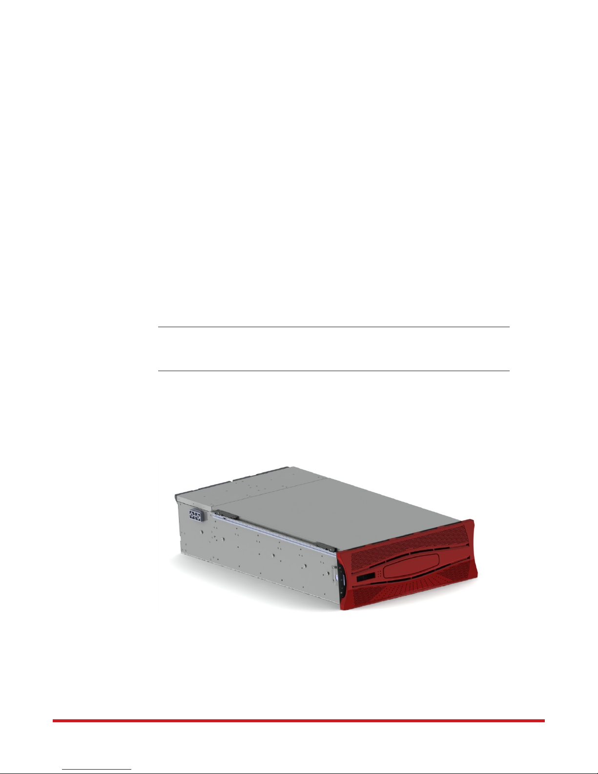
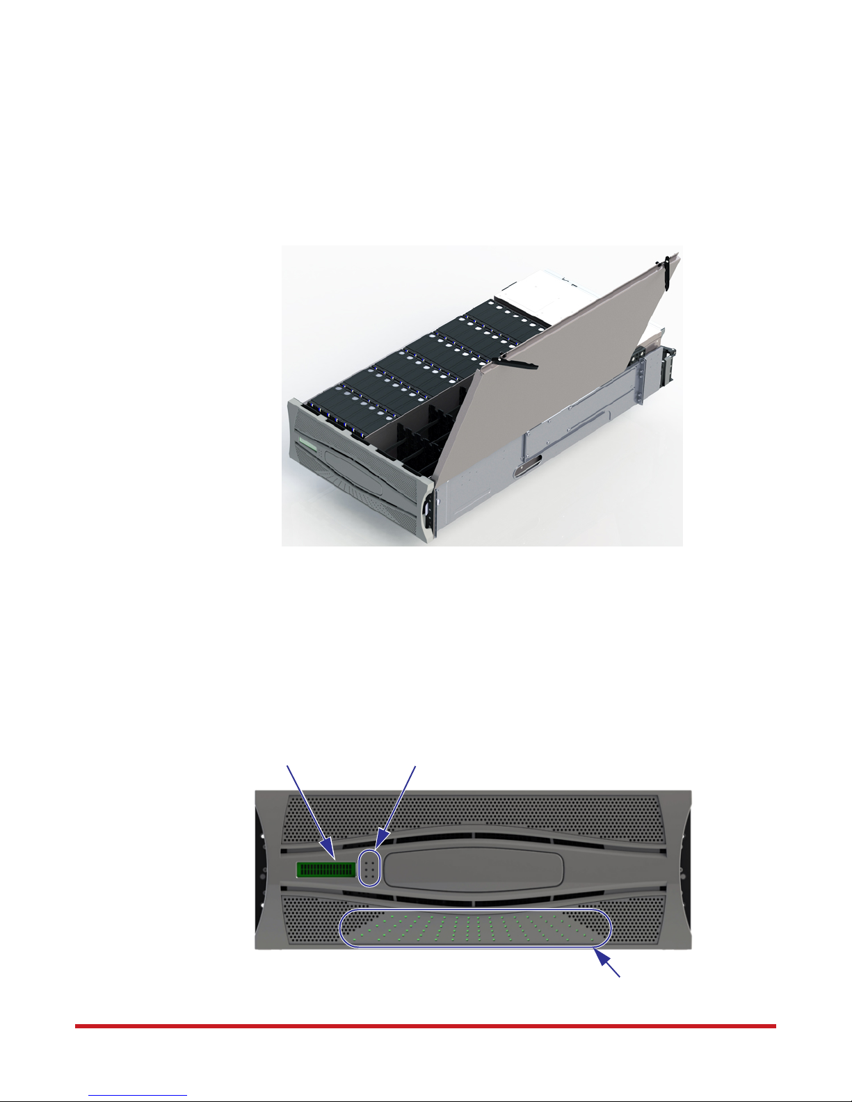
1.1 The StorageScaler 8460 System Overview
The SS8460 is a four-unit (4U), rack-mountable enclosure (Figure 1). Its design concept is
based on a subsystem together with a set of plug-in modules and comprises:
• Enclosure chassis with front panel enclosure status LEDs
• One 2-line liquid crystal display (LCD) module
• Two power and cooling modules
• Two I/O modules
• Two 5V regulator modules
• Up to 84 removable hard disk drives (HDD) in a 6 x 14 matrix
• SAS, SATA, and SSD disk intermix allowed with appropriate disk location placements
Introduction
NOTE :
Plug-in modules are part of the enclosure and must only be removed when
a replacement can be immediately installed. The system must not be run
without all modules in place.
Figure 1. The SS8460
96-30052-001 Rev. A4 DataDirect Networks StorageScaler 8460 User Guide | 10
1.2 Enclosure Chassis
The chassis assembly contains 84 disk bays at the front, each of which accommodates a
plug-in disk module capable of holding a 3.5-inch or 2.5-inch SAS or SATA Hard Disk Drive
(HDD). The 84 disk bays are arranged in six rows of fourteen bays (6 x 14) (Figure 2).
Figure 2. Disk Bays in SS8460
Introduction
The chassis is fitted with 19-inch rack mounting features which enables it to be installed into
19-inch wide racks and uses four EIA units (4U) of rack space.
The front of the enclosure has a LCD, enclosure status LEDs, and disk activity LEDs
(Figure 3). The LCD and LEDs are visible through the front bezel. Refer to Section 3.1.2
"Enclosure Status LEDs" for description of the displayed data and the color and status of the
LEDs.
Figure 3. SS8460 Front with Bezel
LCD
Enclosure Status LEDs
Disk Activity LEDs
96-30052-001 Rev. A4 DataDirect Networks StorageScaler 8460 User Guide | 11
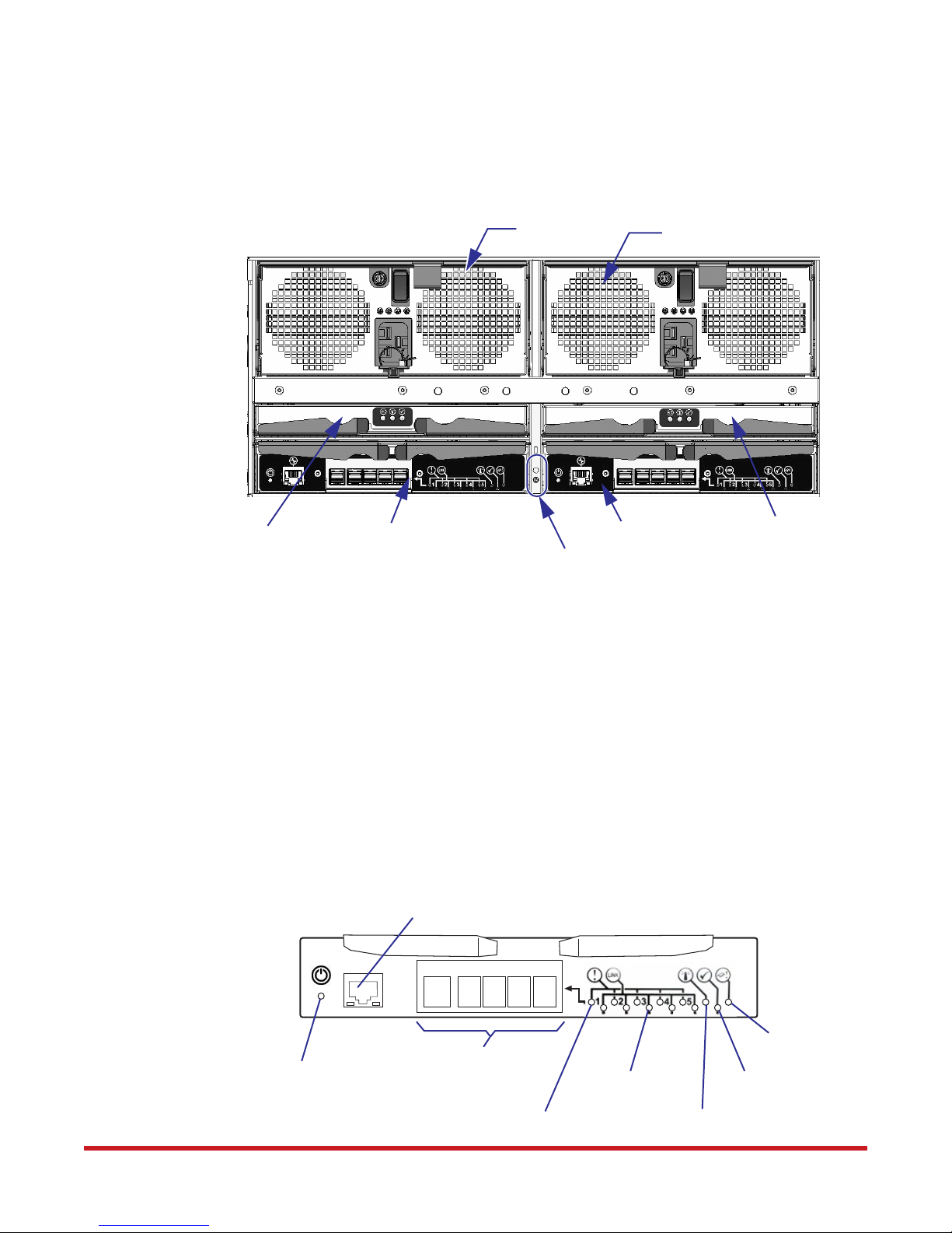
Introduction
At the rear, the chassis assembly contains two power and cooling modules, two I/O modules,
two 5V regulators, and two LEDs (Figure 4). Refer to Section 3.1.2 "Enclosure Status LEDs"
for description of the color and status of the LEDs.
Figure 4. SS8460 Rear View
PCM A
PCM B
5V Regulator A
1.3 I/O Module
The two I/O modules are hot-swappable and provide a redundant path to the disks (Figure 5).
Each I/O module provides five 4-wide SAS data links. These modules communicate inter-IO
information using Ethernet through the baseboard.
There are LEDs mounted on the I/O module to indicate the status of the module. Refer to
Section 3.1.4 "I/O Module LEDs" for description of the color and status of the LEDs.
I/O Module A
Figure 5. An I/O Module
(DO NOT USE)
I/O Module B
Locate and System Fault LEDs
5V Regulator B
Power LED
96-30052-001 Rev. A4 DataDirect Networks StorageScaler 8460 User Guide | 12
Mini SAS HD
Host/Expansion Ports
Link Fault LED
Link Established LED
Fault LED
Module OK LED
Locate Beacon LED
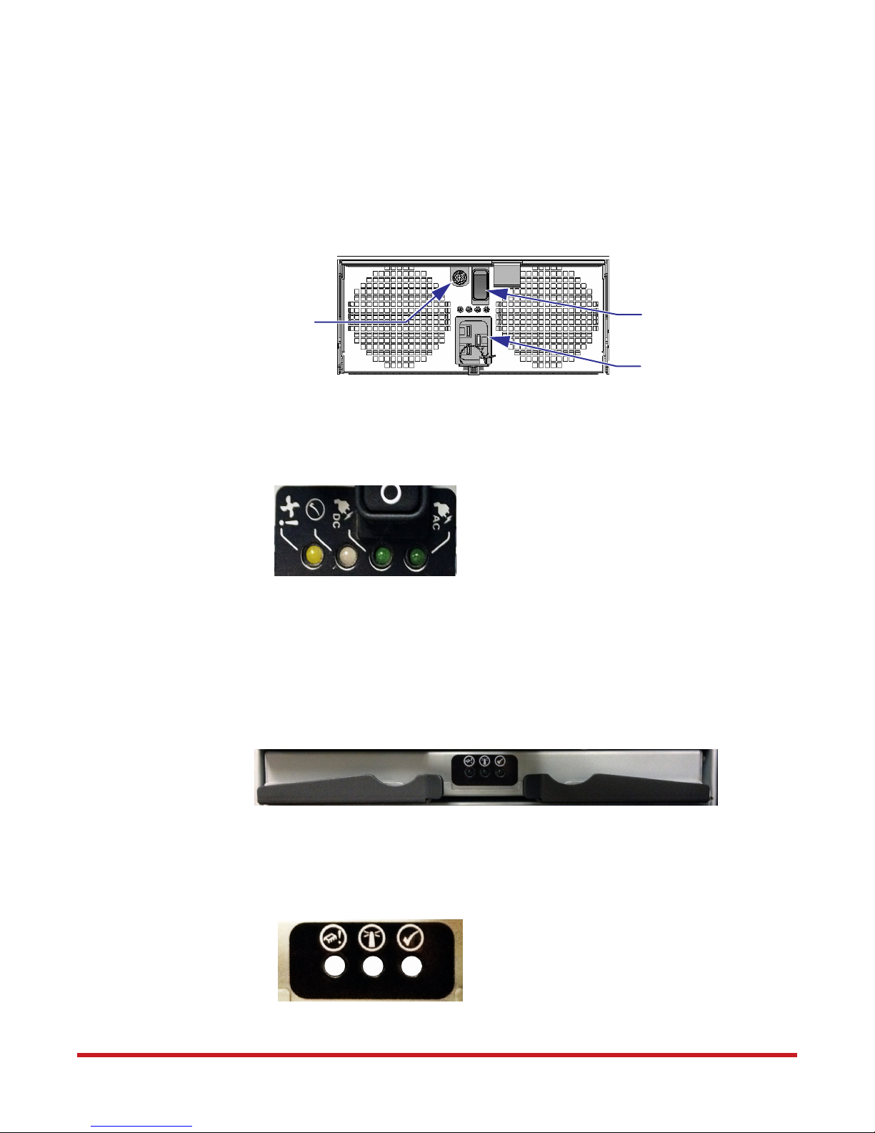
1.4 Power and Cooling Module
Figure 6 illustrates a power and cooling module (PCM). Each SS8460 enclosure houses two,
hot-swappable, fully redundant PCMs located in the rear of the chassis. Each PCM has
integrated fans for cooling the enclosure. A single PCM can provide sufficient power to the
enclosure; however, both modules are required for proper cooling of the enclosure.
Figure 6. A Power and Cooling Module
Introduction
Thumbscrew
There are four LEDs mounted on the PCM to indicate the status of the module and the fans
(Figure 7). Refer to Section 3.1.5 "Power and Cooling Module LEDs" for description of the
color and status of the LEDs.
Figure 7. Power and Cooling Module LEDs
1.5 5V Regulator
Each SS8460 enclosure houses two, hot-swappable, fully redundant 5V regulator modules in
the rear of the chassis. The module will regulate 5V from the 12VDC provided by the PCM.
Power Switch
Power Cord Connector
Figure 8. A 5V Regulator
There are three LEDs mounted on the 5V regulator to indicate the status of the module
(Figure 9). Refer to Section 3.1.6 "5V Regulator LEDs" for description of the color and status
of the LEDs.
Figure 9. 5V Regulator LEDs
96-30052-001 Rev. A4 DataDirect Networks StorageScaler 8460 User Guide | 13
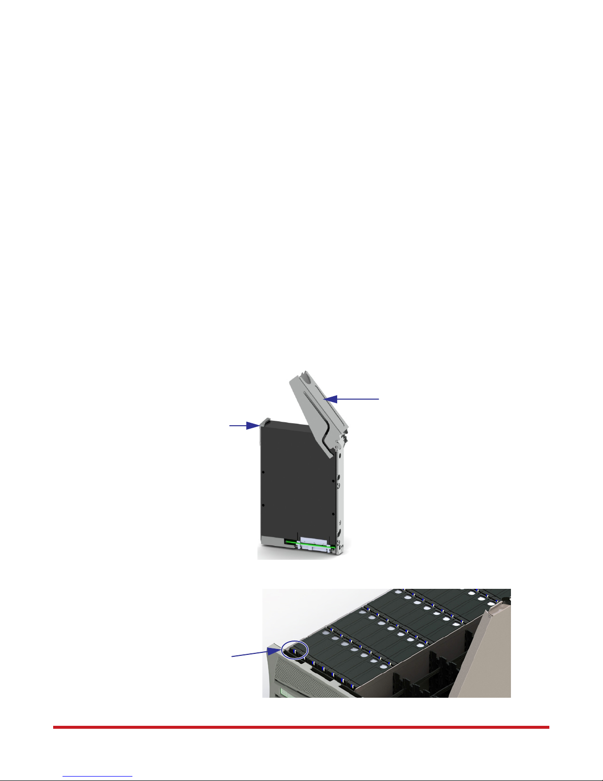
1.6 Disk Modules
A disk module comprises a hard disk mounted in a carrier (Figure 10). Each disk bay can
house a single low profile 1.0-inch high, 3.5-inch or 2.5-inch form factor disk drive in its
carrier. A fully loaded enclosure contains 84 disk modules.
The module handle provides the following functions:
• Camming of the module into and out of disk bays
• Positive “spring loading” of the disk/baseplane connector
There are two light pipes mounted in the carrier to transmit light from the two disk status
LEDs, located on the baseboard, to the surface of the carrier handle (Figure 11). Refer to
Section 3.1.3 "Disk Locate and Status LEDs" for more information.
The SS8460 supports a SAS-to-SATA bridge interposer which allows dual-ported access to
SATA disks and remote power control function for the disks. Note that a SATA interposer
card, which is part of the disk drive carrier assembly, is required to run SATA
HDDs.
Introduction
Figure 10. Disk Modules
Release
Latch
Figure 11. Light Pipes on Disk Modules
Handle Open
Light Pipes
96-30052-001 Rev. A4 DataDirect Networks StorageScaler 8460 User Guide | 14

Chapter 2
Installation
96-30052-001 Rev. A4 DataDirect Networks StorageScaler 8460 User Guide | 15
2.1 Installation Overview
Here is an overview of all the steps for installing a SS8460 system.
• Unpack the SS8460 system
• Rack mount the SS8460 and install cable management assembly. Refer to Appendix A
for physical dimensions and weight of the SS8460.
• Install the disk modules.
• Connect the SS8460 to the storage controllers or expansion enclosures.
• Power up the system.
Observe all conventional ESD precautions when handling the SS8460
!
Warning
plug-in modules and components. Avoid contact with backplane
components and module connectors. Electrostatic discharge can damage
the circuit boards.
Installation Overview
Please note the following before you start:
• If you are installing the enclosure in a rack:
a) Ensure that you have these tools available:
• Long Phillips screwdriver
• Bubble level
b) Arrange for assistance during installation
c) Ensure ahead of time that you have chosen a suitable location for the enclosure or
rack assembly.
• Ensure that the appropriate power is available. DDN recommends an uninterruptable
power supply (UPS) for all data storage configurations. Please refer to the
specifications in Appendix A for SS8460 power ratings.
• Ensure that the area around the enclosure or rack assembly has sufficient cooling and
space around the unit to access cabling.
• When installing disk modules, allow them to acclimate to room temperature prior to
installation. Disks should be stored at room temperature for at least two hours prior to
use.
96-30052-001 Rev. A4 DataDirect Networks StorageScaler 8460 User Guide | 16
2.2 Unpacking the SS8460
Unpacking the SS8460
CAUTION :
Please read all the safety precautions listed in Preface of this manual
prior to unpacking the SS8460 enclosure.
2.2.1 Racked System
If your system is already installed in the racks, refer to the DDN 42U/ 45U 28" Wide Rack
Installation and Service Guide for instructions on removing the system from the shipping
crate and positioning the system.
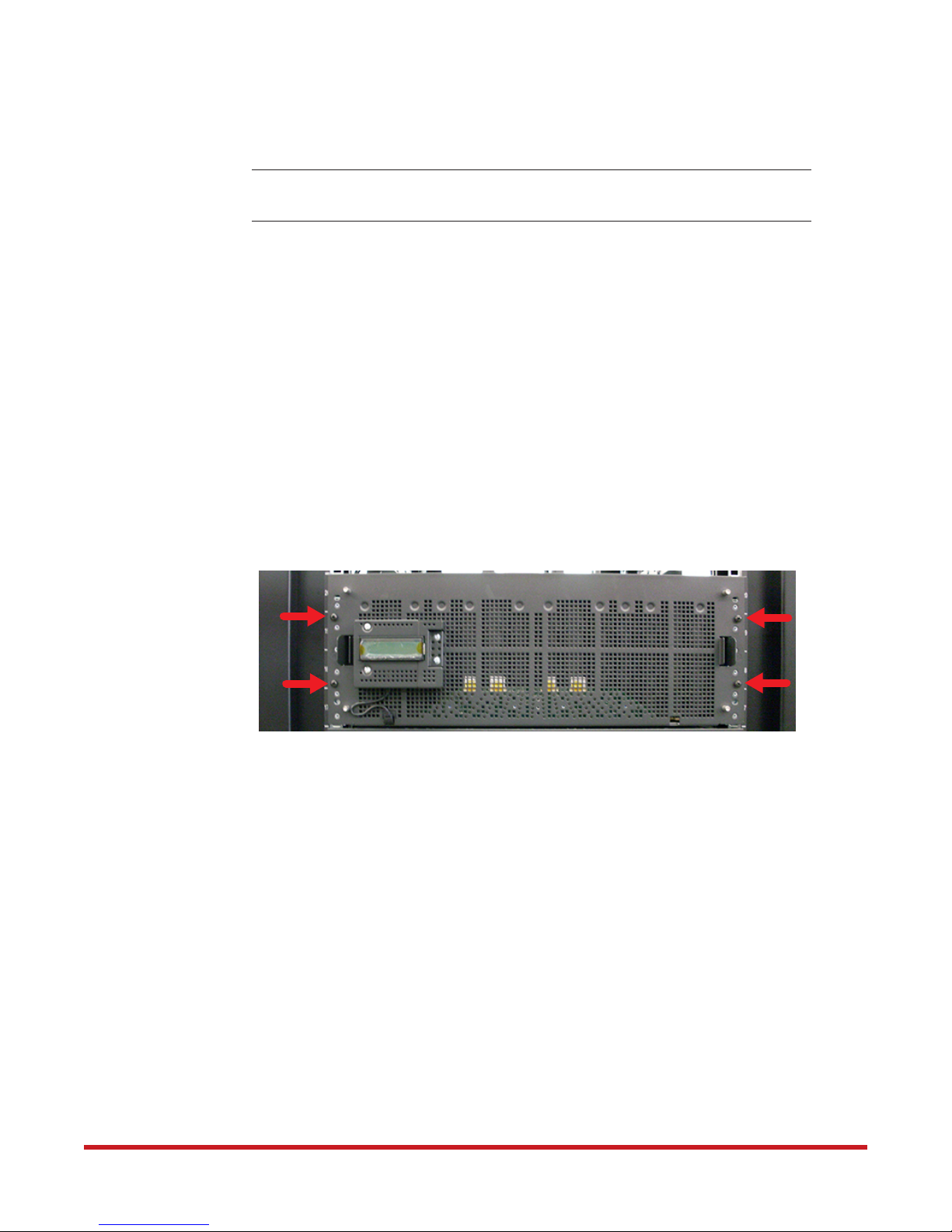
Removing Shipping Screws
There are four shipping screws installed on the front panel that secure the enclosure for
transit in a rack (Figure 12).
These screws must be removed before the enclosure can be pulled out for disk module
installation.
Figure 12. Shipping Screws on Front Panel
2.2.2 Packing List
Your SS8460 ships with the following:
• SS8460 enclosure
• Two power cables
• Rack-mounting hardware
• Cable management hardware
• Disk modules
• Blank modules (if ordered)
Before you unpack your SS8460, inspect the shipping containers for damage. If you detect
damage, report it to your carrier. Retain all boxes and packing materials in case you need to
store or ship the system in the future.
96-30052-001 Rev. A4 DataDirect Networks StorageScaler 8460 User Guide | 17
Unpacking the SS8460
The SS8460 enclosure is very heavy and requires assistance when lifting or
installing the unit in a rack. A SS8460 can weigh up to 244 lbs (110.9 kg)
!
Warning
Perform the following steps:
1. Open the top of the box. Inspect for damage.
2. Remove all the components from the packaging, inspect the SS8460 chassis and all
components for signs of damage. Then place the components on an anti-static surface
until you are ready to use them. If you detect any problems, contact DataDirect
Networks Customer Service as soon as possible.
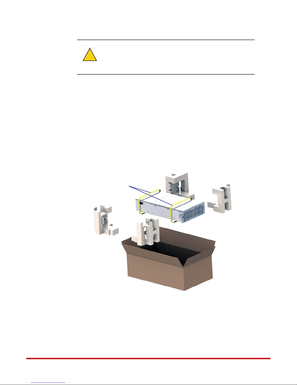
3. There are two nylon lifting straps that are used to remove the enclosure assembly from
the box (Figure 13). A forklift or other mechanical lifting device is highly recommended
to remove the unit.
with disks installed. (It is recommended that no disks are inserted prior to
installing the enclosure in a rack.) A forklift or lift table is recommended
when unpacking and installing the SS8460 to prevent possible injury.
Figure 13. Unpacking the SS8460
Nylon Straps
96-30052-001 Rev. A4 DataDirect Networks StorageScaler 8460 User Guide | 18
 Loading...