

DataDirect Networks StorageScaler 6000 User Manual

DataDirect Networks, Inc
StorageScaler 6000
Drive Enclosure
User Guide
96-00189-001 Rev B
March, 2010
USO RESTRITO

Notices
The information in this document is subject to change without notice.
While every effort has been made to ensure that all information in this document is accurate, DataDirect
Networks accept no liability for any errors that may arise.
No part of this document may be transmitted or copied in any form, or by any means, for any purpose,
without the written permission of DataDirect Networks.
March, 2010 96-00189-001 Rev B
ii
96-00189-001 REV B
USO RESTRITO

Contents
DataDirect Networks StorageScaler 6000 User Guide Rev B 1
Table of Contents
1Introduction ..................................................................................................................................... 1
1.1 The StorageScaler 6000 System
................................................................................................ 1
1.2 Enclosure Core Product
.............................................................................................................. 2
1.2.1 Enclosure Chassis
.............................................................................................................. 2
1.3 The Plug-in Modules
................................................................................................................... 3
1.3.1 Power Cooling Module (PCM)
............................................................................................ 3
1.3.2 Input/Output (I/O) Module
................................................................................................... 4
1.3.3 Drive Carrier Module and Status Indicator
......................................................................... 5
1.3.4 DEM Card
........................................................................................................................... 6
1.4 Front Panel Indicators
................................................................................................................. 7
1.5 Environment
................................................................................................................................ 8
1.6 StorageScaler 6000 Technical Specification
............................................................................... 9
1.6.1 Dimensions
......................................................................................................................... 9
1.6.2 Weight
................................................................................................................................ 9
1.6.3 AC INPUT PCM
.................................................................................................................. 9
1.6.4 DC INPUT PCM
............................................................................................................... 10
1.6.5 DC OUTPUT PCM
........................................................................................................... 10
1.6.6 PCM Safety and EMC Compliance
.................................................................................. 10
1.6.7 Power Cord
...................................................................................................................... 10
2 Getting Started .............................................................................................................................. 11
2.1 Planning Your Installation
.......................................................................................................... 11
2.1.1 Enclosure Bay Numbering Convention
............................................................................ 12
2.2 Enclosure Installation Procedures
............................................................................................. 14
2.3 I/O Module Configurations
........................................................................................................ 14
2.3.1 Controller Options
............................................................................................................ 14
2.4 DEM
.......................................................................................................................................... 15
2.5 Drive Enclosure Device Addressing
.......................................................................................... 15
2.6 Grounding Checks
..................................................................................................................... 15
3 Operation
....................................................................................................................................... 17
3.1 Before You Begin
...................................................................................................................... 17
3.2 Power On / Power Down
........................................................................................................... 17
3.2.1 PCM LEDs
........................................................................................................................ 17
3.2.2 I/O Panel LEDs
................................................................................................................. 18
4 Troubleshooting and Problem Solving ....................................................................................... 19
4.1 Overview
................................................................................................................................... 19
4.2 Initial Start-up Problems
............................................................................................................ 19
4.2.1 Faulty Cords
..................................................................................................................... 19
4.2.2 Alarm Sounds On Power Up
............................................................................................ 19
4.2.3 Green “Signal Good” LED on I/O Module Not Lit
............................................................. 19
4.2.4 Computer Doesn’t Recognize the
Storage Scaler 6000 Subsystem ............................... 20
4.3 LEDs
.......................................................................................................................................... 20
4.3.1 HDD (Hard Disk Drive)
..................................................................................................... 20
4.3.2 PCM (Power Cooling Module)
.......................................................................................... 21
4.3.3 DEM (Drive Expander Module)
........................................................................................ 21
USO RESTRITO

2 DataDirect Networks StorageScaler 6000 User Guide Rev B
4.3.4 I/O Module ....................................................................................................................... 22
4.3.5 Front Panel Drive Activity Indicators
................................................................................ 23
4.4 Troubleshooting
........................................................................................................................ 24
4.4.1 Thermal Control
............................................................................................................... 24
4.4.2 Thermal Alarm
................................................................................................................. 25
4.4.3 Thermal Shutdown
........................................................................................................... 25
4.5 Dealing with Hardware Faults
................................................................................................... 26
4.6 Replacing a Module
.................................................................................................................. 26
4.6.1 Power Cooling Modules
................................................................................................... 26
4.6.2 I/O Module
....................................................................................................................... 28
4.6.3 Replacing the Drive Carrier Module
................................................................................. 29
4.7 Replacing the DEM
................................................................................................................... 30
Appendix A Tier Mapping
.................................................................................................................. 31
Appendix B Rack Mounting ............................................................................................................... 37
USO RESTRITO

Preface
DataDirect Networks StorageScaler 6000 User Guide Rev B 3
Preface
What is in this guide
This user guide gives you step-by-step instructions on
how to install, configure, and connect the
StorageScaler 6000 storage subsystem to your host computer system, as well as to use and maintain the
system.
Who should use this guide
This user guide assumes that you have a working
knowledge of the Serial Attached SCSI (SAS) protocol
environments into which you are installing the StorageScaler 6000 system.
International St andards
The StorageScaler 6000 storage system complies with the requirements of the following agencies and
standards:
•CE
•UL
Potential for Radio Frequency
Interference
USA Federal Communications Commission (FCC)
Note T
his equipment has been tested and found to comply with the limits for a class A digital device, pursuant
to Part 15 of the FCC rules. These limits are designed to provide reasonable protection against harmful
interference when the equipment is operated in a commercial environment. This equipment generates,
uses and can radiate radio frequency energy and, if not installed and used in accordance with the
instruction manual, may cause harmful interference to radio communications. Operation of this
equipment in a residential area is likely to cause harmful interference in which case the user will be
required to correct the interference at his own expense.
Properly shielded and grounded cables and connectors must be used in order to meet FCC emission
li
mits. The supplier is not responsible for any radio or television interference caused by using other than
recommended cables and connectors or by unauthorized changes or modifications to this equipment.
Unauthorized changes or modifications could void the user’s authority to ope rate the equipment.
This device complies with Part 15 of the FCC Rules. Ope
ration is subject to the following two conditions:
(1) this device may not cause harmful interference, and (2) this device must accept any interference
received, including interference that may cause undesired operation.
European Regulations
This equipment complies with European Regulations EN 55022 Class A: Limits and Methods of
Measurement of Radio Disturbance Characteristics of Information Technology Equipment and EN500821: Generic Immunity.
USO RESTRITO
Preface
4 DataDirect Networks StorageScaler 6000 User Guide Rev B
Qualified Personnel
Qualified personnel are defined as follows:
• Service Person: A person having appropriate technical training and experience necessary to be
aware of hazards to which that person may be exposed in performing a task and of measures to
minimize the risks to that person or other persons.
• User/Operator: Any person other than a Service Person.
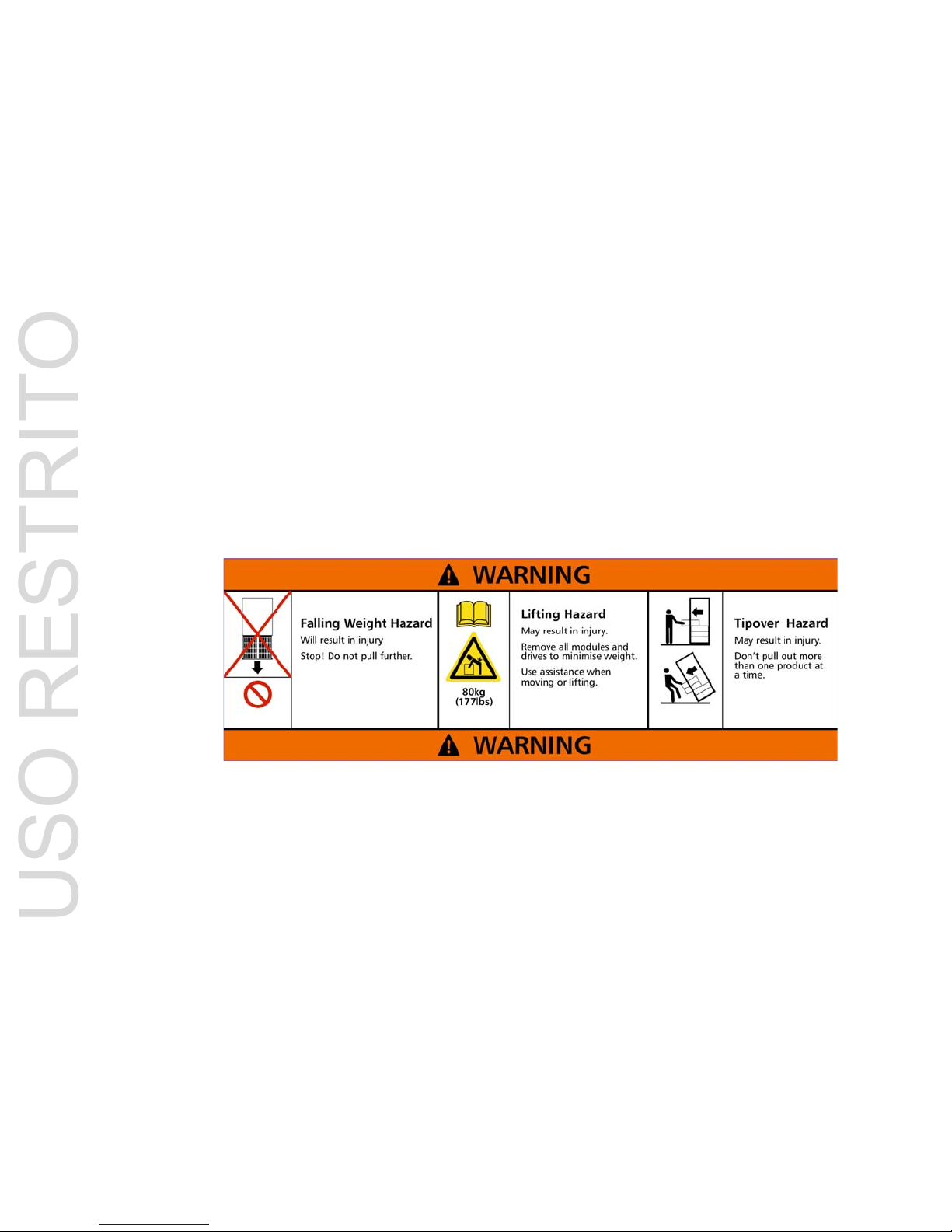
Safe Handling
• Remove drives to minimize weight.
• Do not try to lift the enclosure by yourself.
• Do not lift the StorageScaler 6000 by the handles on the power cooling module (PCM); they are not
designed to support the weight of the populated enclosure.
Weight Handling Label: Lifting and Tipping
Safety
Important If this equipment is used in a manner not speci fied by the manuf acturer, the protec tion provided
by the equipment may be impaired.
Warning The StorageScaler 6000 enclosure MUS
T be grounded before applying power.
Unplug the unit if you think that it has become damaged in any way and b efore you move it.
Caution Plug
-in modules are part of the fire enclosure and must only be removed when a replacement can be
immediately added. The system must not be run without all units in place. Operate the system with the
enclosure top cover closed.
• In order to comply with applicable safety, emissio
n and thermal requirements no covers should be
removed.
USO RESTRITO
Preface
DataDirect Networks StorageScaler 6000 User Guide Rev B 5
• The StorageScaler 6000 unit must only be operated from a power supply input voltage range of 200
V AC to 240 V AC.
• The plug on the power supply cord is used as the main disconnect device. Ensure that the socket
outle
ts are located near the equipment and are easily accessible.
Warning To ensure protection against electric shock caused by HIGH LEAKAGE CURRENT (TOUCH
CURRENT), the StorageScaler 6000 must be connected to at least two separate and independent
sources. This is to ensure a reliable earth connection.
Warning The equipment is intended to operate with two (2) working PCMs. Before removing a PCM, please
d
isconnect the power from the power supply, by either the switch (where present) or by physically
removing the power source, prior to removing the PCM from the enclosure/shelf.
• Do not remove a faulty PCM unless you have a replacement unit of the correct type ready for
insertion.
• A safe electrical earth connection must be provided to the power cord.
• Provide a suitable power source with electrical o
verload protection to meet the requirements laid
down in the technical specification.
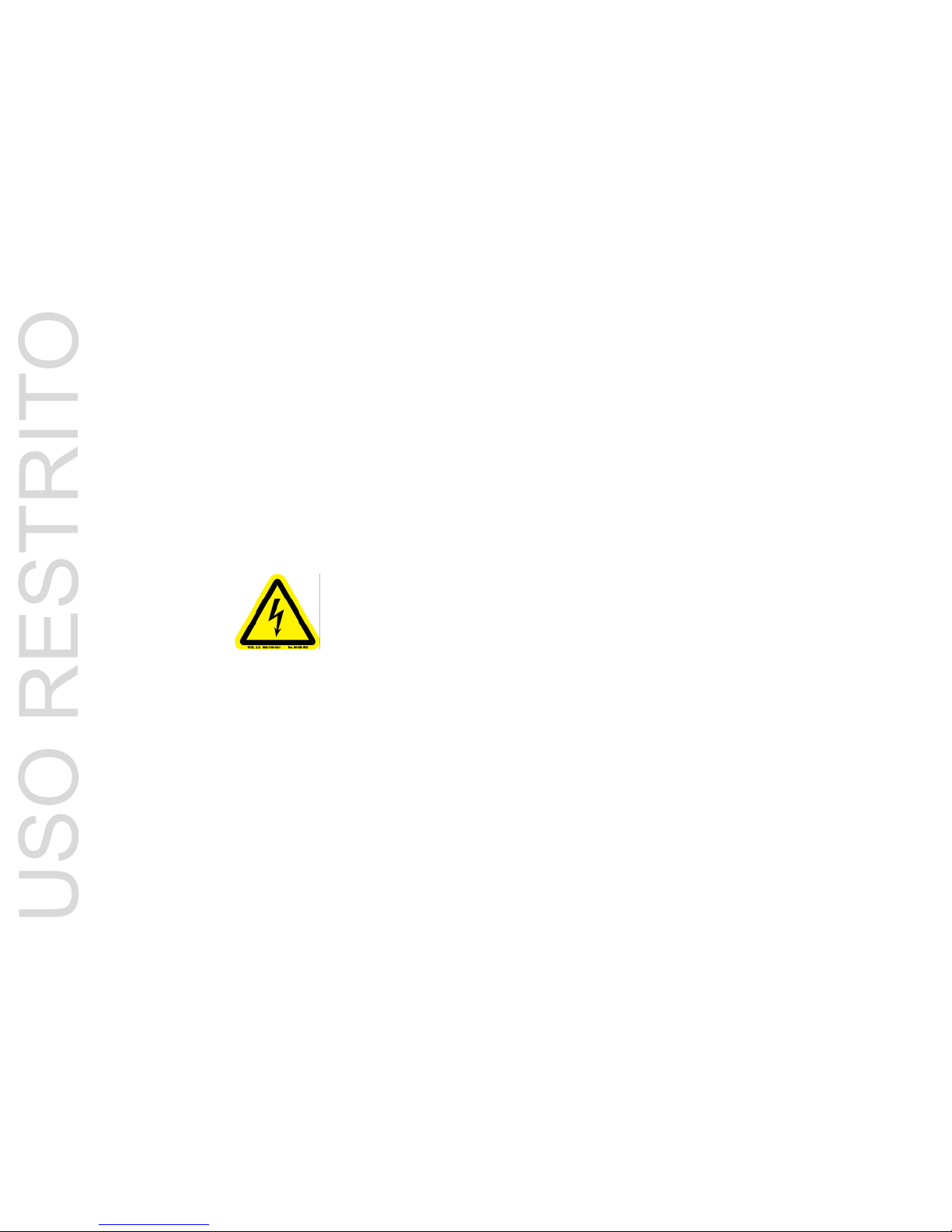
Warning Do not remove covers from th
e PCM. Danger of electric shock inside. Return the PCM to your
supplier for repair.
PCM Safety Label: Electric Shock Hazard Inside
Warning Operation of the Enclosure with ANY mo
dules missing will disrupt the airflow and the drives will
not receive sufficient cooling. It is ESSENTIAL that all apertures are filled before operating the
unit.
Recycling of Waste Electrical and Electronic
Equipment (WEEE)
At the end of the product’s life, all scrap/ waste electrical and electronic equipment should be recycled in
accordance with National regulations applicable to the handling of hazardous/ toxic electrical and
electronic waste materials.
Please contact your supplier for a copy of the Recycling Procedures applicable to your product.
Important Observe all applicable safety precautions, e.g.
weight restrictions, handling batteries and lasers
etc, detailed in the preceding paragraphs when dismantling and disposing of this equipment
USO RESTRITO

Preface
6 DataDirect Networks StorageScaler 6000 User Guide Rev B
Rack System Precautions
The following safety requirements must be considered when the unit is mounted in a rack.
• The rack construction must be capable of supporting the total weight of the installed enclosure(s)
and the design should incorporate stabilizing features suitable to prevent the rack from tipping or
being pushed over during installation or in normal use.
• When loading a rack with the units, fill the rack from the bottom up and empty from the top down.
• Always remove all modules and drives, to minimize weight, before loading the chassis into a rack.
Warning It is recommended that you do not slide more than one enclosure out of the rack at a time, to avoid
danger of the rack tipping over.
• When mounting in a rack, ensure that the enclosure is pushed fully back into the rack.
• The system must be operated with low pressure rear exhaust installation. (The back pressure
created by rack doors and obstacles should not exceed 5 pascals [0.5mm water gauge].)
• The rack design should take into consideration the
maximum operating ambient temperature for the
unit is 35°C.
• The rack should have a safe electrical distribution system. It must provide over current protec
tion for
the unit and must not be overloaded by the total number of units installed in the rack. Consideration
of the units nameplate rating should be used when addressing these concerns.
• The electrical distribution system must provide a reliable earth ground for each unit and the rack.
• Each power supply in each unit has an earth leakage current o
f 1.5mA. The design of the electrical
distribution system must take into consideration the total earth leakage current from all the power
supplies in all the units. The rack will require labelling with “HIGH LEAKAGE CURRENT. Earth
connection essential before connecting supply.”
• The rack when configured with the units must meet
the safety requirements of UL 60950 and IEC
60950.
USO RESTRITO
Preface
DataDirect Networks StorageScaler 6000 User Guide Rev B 7
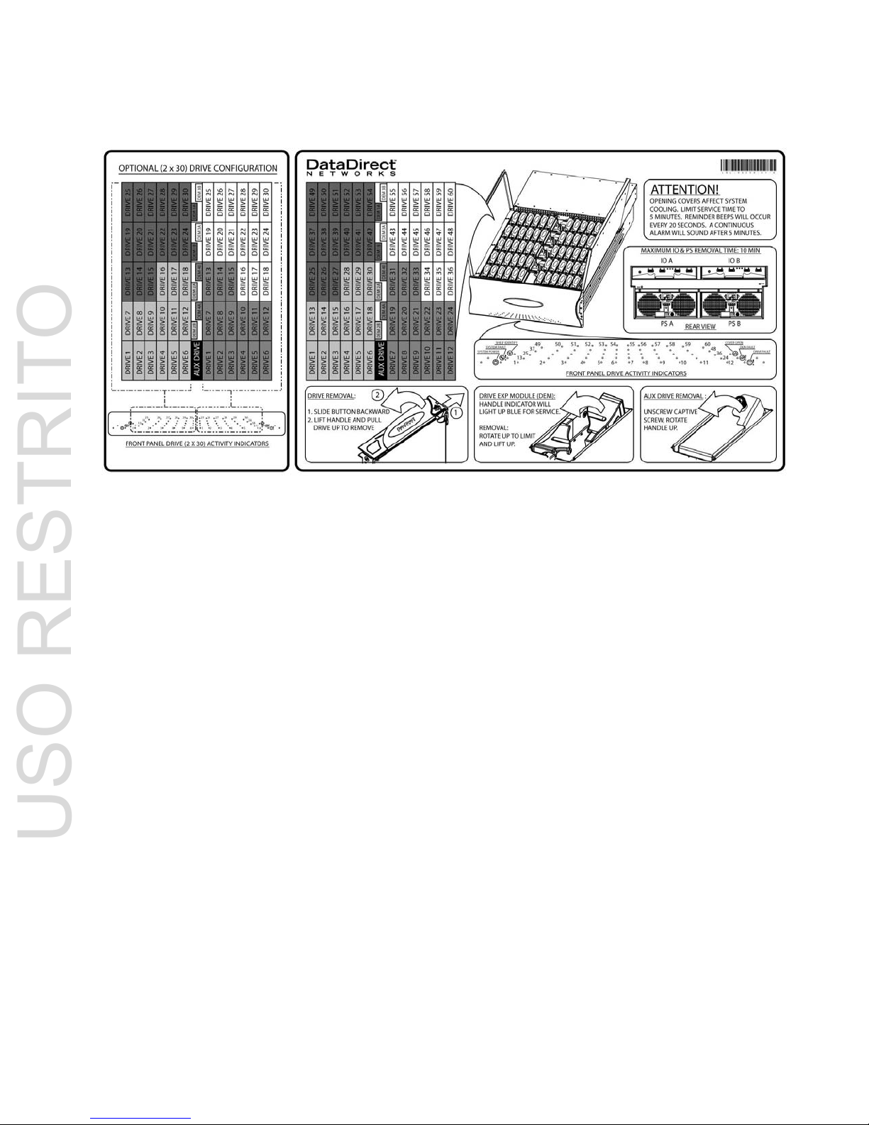
Cover Label
ESD Precautions
Caution It is recommended that you fit and check a suitable anti-static wrist or ankle strap and observe all
conventional ESD precautions when handling StorageScaler 6000 plug-in modules and componen ts.
Avoid contact with backplane components and module connectors, etc.
Data Security
• Power down your host computer and all attached peripheral devices before beginning installation.
• Each enclosure contains up to 60 removable disk dri
ve modules. Disk units are fragile. Handle them
with care, and keep them away from strong magnetic fields.
• All th
e supplied plug-in modules and blanking plates must be in place for the air to flow correctl y
through the enclosure and also to complete the internal circuitry.
• If the subsystem is used with modules or blanking
plates missing for more than a few minutes, the
enclosure can overheat, causing power failure and data loss. Such use may also invalidate the
warranty.
• If you remove a drive module, replace it immediately. If
it is faulty, replace it with a drive module of
the same type and capacity
USO RESTRITO

Preface
8 DataDirect Networks StorageScaler 6000 User Guide Rev B
• Ensure that all disk drives are removed from the enclosure before attempting to move the rack
installation.
• Do not abandon your backup routines. No system is completely foolproof.
USO RESTRITO
Introduction
DataDirect Networks StorageScaler 6000 User Guide Rev B 1
Chapter 1
Introduction
1.1 The StorageScaler 6000 System
The StorageScaler 6000 storage system is an ultra dense 4U 60 disk drive enclosure based on 3.5 inch
SAS or SATA Hard Disk Drives (HDDs). Figure 1–1 and Figure 1–2 sh
ow front and rear views of a
StorageScaler 6000 enclosure respectively. Module a
nd major components and their locations are
shown in Figure 1–3.
Figure 1–1 T
he StorageScaler 6000 System - front open view
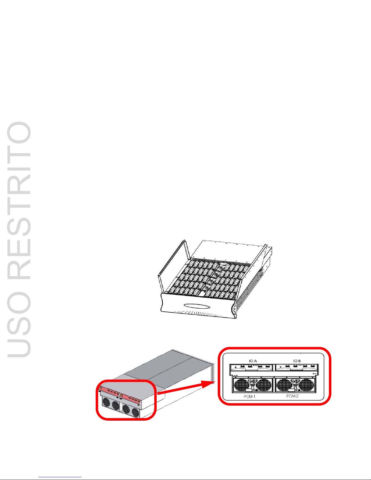
Figure 1–2 T
he StorageScaler 6000 System - rear isometric and rear views
USO RESTRITO
StorageScaler 6000 User Guide (96-00189-001 Rev B)
2 DataDirect Networks StorageScaler 6000 User Guide Rev B
1.2 Enclosure Core Product
The StorageScaler 6000 design concept is based on a subsystem together with a set of plug-in modules
and (as supplied) comprises:
• En
closure Chassis with integral Front Panel Drive Status Indicator (Figure 1–10).
• Two (2) 1865W Power Cooling (PCM) plug-in modules (Figure 1–4).
• Two (2) plug-in Input/Output (I/O) modules (Figure 1–6).
• A midplane separates the front and back of the cha
ssis and provides the interconnect system
between the PCMs, I/O modules, and the baseboard.
• Up to 60 top loadable HDDs in a 5x12 matrix.
• Eight (8) SAS DEMs.
1.2.1 Enclosure Chassis
The chassis assembly contains 60 drive bays at the front, each of which accommodates a plug-in drive
carrier module capable of holding a 3.5 inch SAS or SATA Hard Disk Drive (HDD). The 60 drive bays are
arranged in five rows of twelve drives (5x12). At the rear, the chassis assembly contains two (2) PCMs
and two (2) I/O modules (Figure 1–3). The chassis is fitted with 19-inch
rack mounting features which
enables it to be fitted
to 19-inch racks and uses four (4) EIA units of rack space.
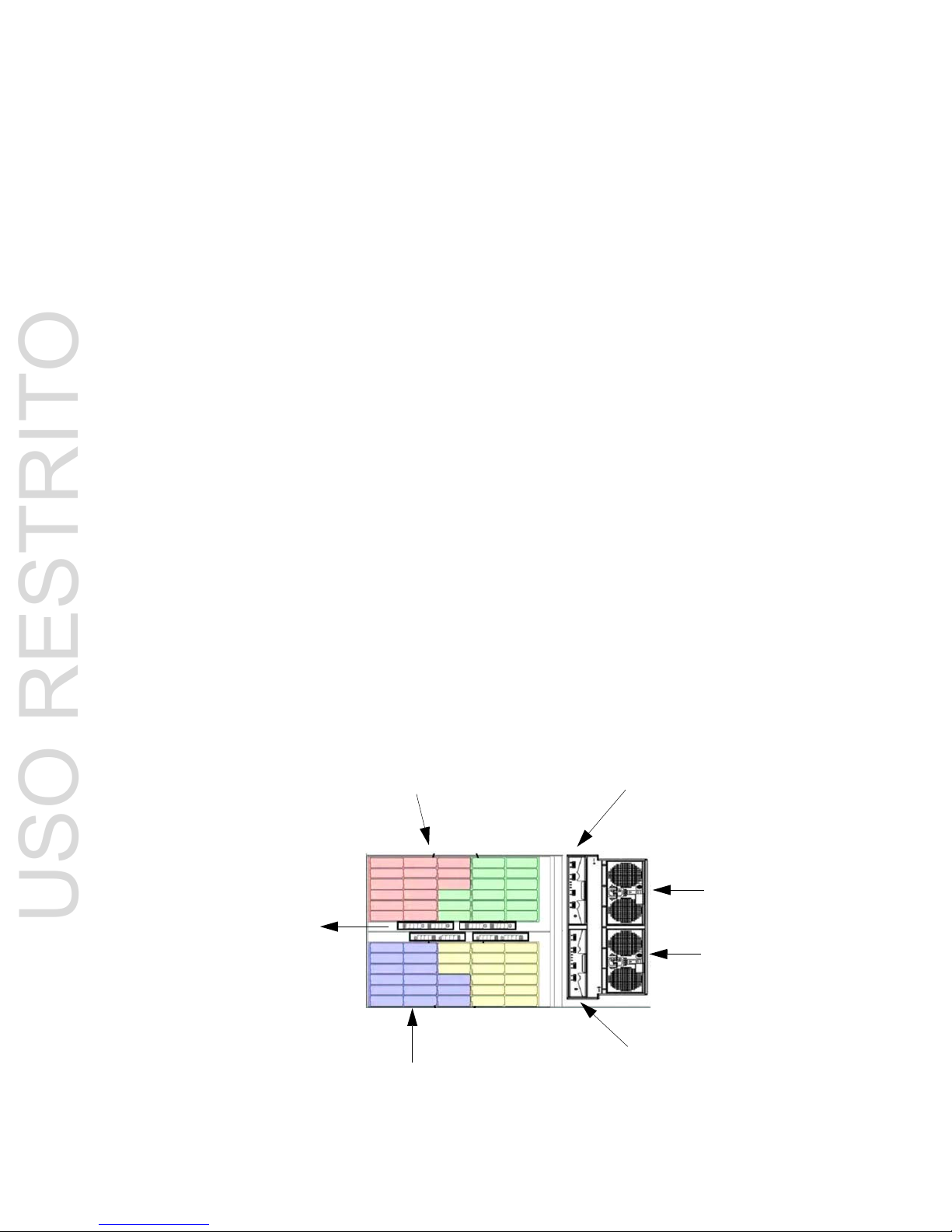
Figure 1–3 Storage
Scaler 6000 Module Locations (Top View)
30 Drive Bays
30 Drive Bays
I/O-B
I/O-A
8 DEMs
FRONT
REAR
PCM-2
PCM-1
USO RESTRITO
Introduction
DataDirect Networks StorageScaler 6000 User Guide Rev B 3
1.3 The Plug-in Modules
The StorageScaler 6000 Enclosure requires the following modules for normal operation:
• Power Cooling Module (PCM)
• Input/Output Module (I/O)
• Drive Carrier Module
•DEM
1.3.1 Power Cooling Module (PCM)
Two (2) auto ranging AC 1865W Power Cooling modules (Figure 1–4) are supplied already mounted in
the rear of the enclosure as part of
the subsystem core product.
.
The StorageScaler 6000 must always be operated with two (2) Power Cooling Modules fitted (2 PCMs).
Module replacement should only take a few minutes to perform but must be completed within 10 minutes
from removal of the failed module. Four (4) LEDs mounted on the PCM (Figure 1–5 and Table 1–1)
indicate the status of the PCM and the fans. PCM voltag
e operating ranges are nominally 200V to 240V
AC.
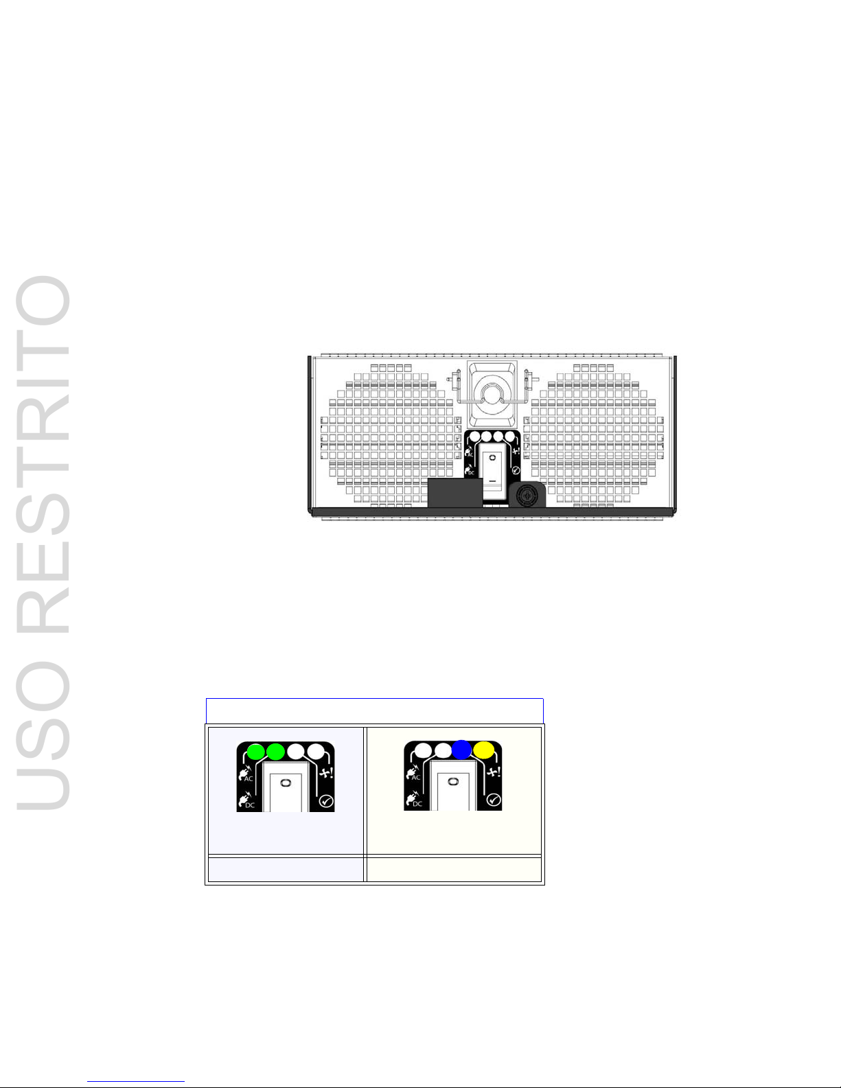
Figure 1–4 Power Cooling Module (1)
Figure 1–5 PCM LEDs V
iew: Normal/Faults
PCM LEDs
Normal Operation LEDs Faults LEDs
USO RESTRITO
StorageScaler 6000 User Guide (96-00189-001 Rev B)
4 DataDirect Networks StorageScaler 6000 User Guide Rev B
Table 1–1 PCM LEDs
1.3.2 Input/Output (I/O) Module
The StorageScaler 6000 storage subsystem includes an enclosure with rear facing bays which house
two (2) I/O modules (Figure 1–6). Processors housed on the I/O mo
dules provide enclosure
management and interface to devices on the Backplane, PCM,
and Display Panel in order to monitor
internal functions. The plug-in I/O modules have been designed for integration into a StorageScaler 6000
storage subsystem, providing external SAS cable interfacing with up to 60 SAS or SATA disk drives.
ICON LED Description COLOR Normal Behavior
PCM AC ok GREEN ON-AC inp
ut to PCM within tolerances.
OFF-faile
d PCM
PCM DC ok GREEN ON-DC output of PCM within tolerances.
OFF-faile
d PCM
PCM Fault AMBER ON-PC
M fault detected
OFF-no
detected PCM faults.
PCM ID BLUE ON-receiving SES
Identify command
OFF-NOT receiving SES Identify command
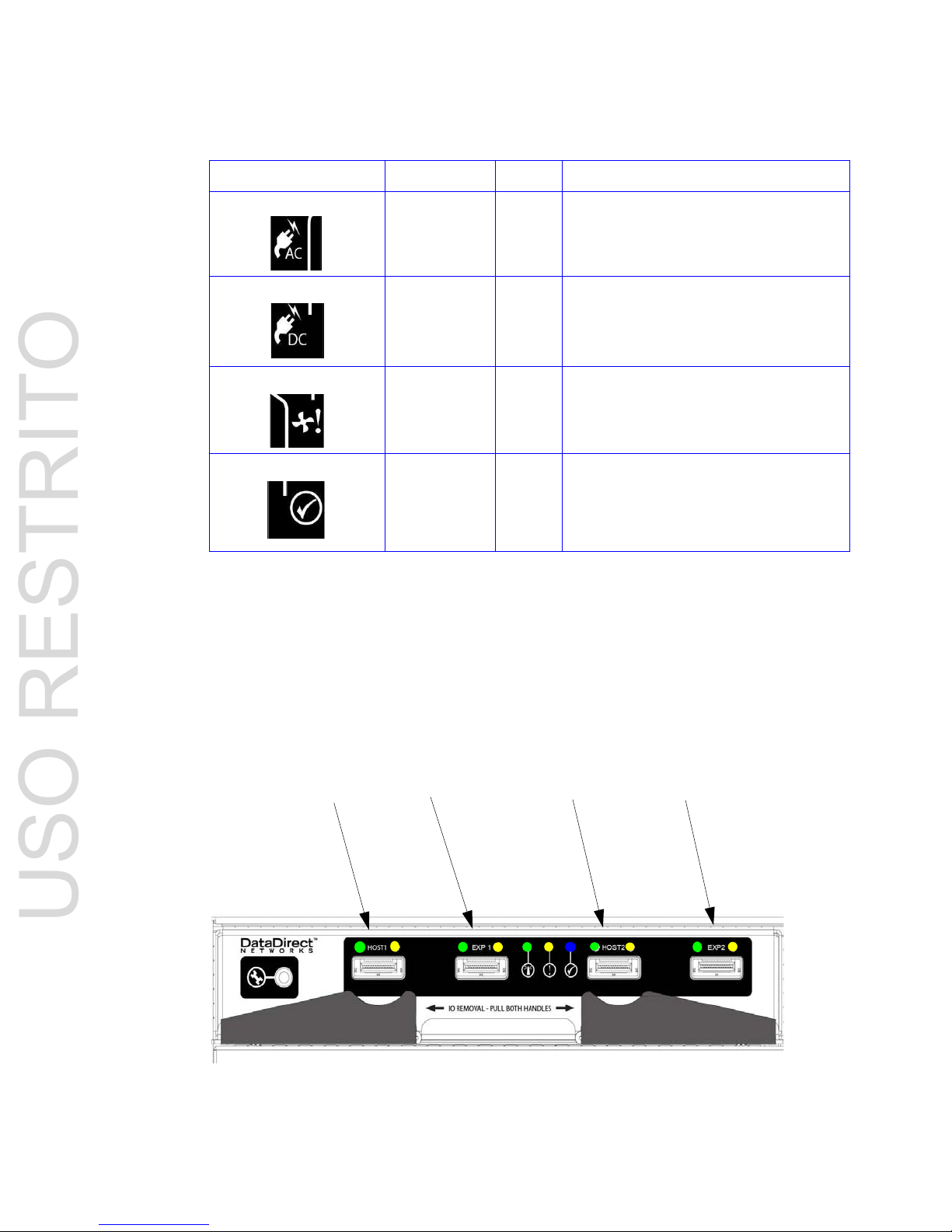
Figure 1–6 I/O Module
Host Port 1 Expansion Port 1 Host Port 2 Expansion Port 2
USO RESTRITO

Introduction
DataDirect Networks StorageScaler 6000 User Guide Rev B 5
ITable 1–2 defines the LED indicators incorporated on the I/O module.
1.3.3 Drive Carrier Module and St atus Indicator
The Drive Carrier Module comprises a hard disk mounted in a carrier (Figure 1–7). Each drive bay can
house a single Low Profile 1.0 inch high, 3.5 inch form
factor disk drive in its carrier. A fully loaded
enclosure contains 60 drive carrier modules.
The handle provides the following functions:
• Camming of carrier into and out of drive bays.
• Positive 'spring loading' of th
e drive/baseplane connector.
• The handle assembly also incorporates a Drive Status LED (Figure 1–7).
Note T
he enclosure system design allows for drive bays to be left empty without the need for fitting dummy
drive carriers.
Table 1–2 I/O Mo
dule LEDs
LED Description Color Normal Behavior
Host Port 1
Expansion Port 1
Host Port 2
Expansion Port 2
SAS Link Green ON-a
valid SAS link established on at least 1 of the 4
SAS links of the 4-wide SAS port
OFF-no SAS
links
Host Port 1
Expansion Port 1
Host Port 2
Expansion Port 2
SAS Link Fault Amber ON-a detec
table fault on at least 1 of the 4 SAS links
of the 4-wide SAS port
OFF-no detectable faults
I/O Module OK Green ON-p
roperly booted and functioning correctly
OFF-I/O
Module internal fault
I/O Module Fault Amber ON-I/O modul
e fault detected
OFF-n
o detected I/O module faults
I/O Module Identify Blue ON-receiving SES Identify command
OFF-NOT receiving SES
Identify command
USO RESTRITO
 Loading...