

DataDirect Networks SFA12Ki, SFA12K-20, SFA12KXE, SFA12K-40, SFA12K-20E Installation & Configuration Manual
...
SFA12K Series
Hardware Installation & Configuration Guide
SFA OS Version 2.3.1 | 96-30051-001 | Revision D3
SFA12Ki | SFA12KX | SFA12K-40 | SFA12K-20 | SFA12KXE | SFA12K-20E

Important Information
Information in this document is subject to change without notice and does not represent a commitment
on the part of DataDirect Networks, Inc. No part of this manual may be reproduced or transmitted in any
form or by any means, electronic or mechanical, including photocopying and recording, for any purpose
other than the purchaser’s personal use without the written permission of DataDirect Networks, Inc.
© 2015 DataDirect Networks, Inc. All rights reserved.
DataDirect Networks, the DataDirect Networks logo, DDN, DirectMon, Enterprise Fusion Architecture,
EFA, ES7K, ES12K, EXAScaler, GRIDScaler, GS7K, GS12K, IME, Infinite Memory Engine, Information in
Motion, In-Storage Processing, MEDIAScaler, NAS Scaler, NoFS, ObjectAssure, ReACT, SFA, SFA 10000
Storage Fusion Architecture, SFA10K, SFA12K, SFA14K, SFA7700, SFX, Storage Fusion Architecture,
Storage Fusion Fabric, Storage Fusion Xcelerator, SwiftCluster, WOS, the WOS logo are registered
trademarks or trademarks of DataDirect Networks, Inc. All other brand and product names are
trademarks of their respective holders.
DataDirect Networks makes no warranties, express or implied, including without limitation the implied
warranties of merchantability and fitness for a particular purpose of any products or software.
DataDirect Networks does not warrant, guarantee or make any representations regarding the use or the
results of the use of any products or software in terms of correctness, accuracy, reliability, or otherwise.
The entire risk as to the results and performance of the product and software are assumed by you. The
exclusion of implied warranties is not permitted by some jurisdictions; this exclusion may not apply to
you.
In no event will DataDirect Network, their directors, officers, employees, or agents (collectively
DataDirect Networks) be liable to you for any consequential, incidental, or indirect damages, including
damages for loss of business profits, business interruption, loss of business information, and the like,
arising out of the use or inability to use any DataDirect product or software even if DataDirect Networks
has been advised of the possibility of such damages by you. Because some jurisdictions do not allow the
exclusion or limitation of liability for consequential or incidental damages, these limitations may not
apply to you. DataDirect Networks liability to you for actual damages from any cause whatsoever, and
regardless of the form of the action (whether in contract, tort including negligence, product liability or
otherwise), is limited to the sum you paid for the DataDirect product or software.
October 2015
96-30051-001 Rev. D3 DDN SFA12K (SFA OS 2.3.1) Hardware Installation & Configuration Guide | 2

Preface
This document provides installation and set up information for getting your DataDirect
Networks SFA12K system up and running as quickly as possible. The features and functions
of the SFA12K are fully documented in the SFA OS User Guide.
In this document, except where otherwise specified, SFA12K represents SFA12K-20,
SFA12KX, SFA12K-40, SFA12KXi, SFA12KXE, and SFA12K-20E.
This version of SFA12K Hardware Installation & Configuration Guide is specific to SFA OS
version 2.3.1. Information given in this document applies to the following configurations,
unless otherwise noted:
• SFA12K-20—the block storage appliance
• SFA12KX/12K-40—the high performance block storage appliance, twice the disk
bandwidth performance of SFA12K-20
• SFA12KXi—the ultra-high IOPS and bandwidth block storage appliance
• SFA12KXE/12K-20E—thefilesystemappliancemodel with embedded virtual machine
support for DDN GRIDScaler and DDN EXAScaler scalable parallel file system
solutions
Refer to the SFA OS Compatibility Guide for the list of expansion enclosures, disk drives,
certified solutions, client operating systems, and HBAs and HCAs that are currently
supported.
Related Documentation
• SFA OS Product Release Notes
• SFA OS Compatibility Guide
• SFA OS CLUI Command Reference
• SFA API Reference Guide
• 42U/45U 28" Wide Rack Installation and Service Guide
• StorageScaler 8460 User Guide
• StorageScaler 7000 User Guide
• EXAScaler Admin Guide
• GRIDScaler Admin Guide
96-30051-001 Rev. D3 DDN SFA12K (SFA OS 2.3.1) Hardware Installation & Configuration Guide | 3

Table of Contents
1. Installation Overview . . . . . . . . . . . . . . . . . . . . . . . . . . . . . . . . . . . . . . . . . . . . . . . . . . . . . . . . . . . . . . . . . . . .9
2. Unpacking the System . . . . . . . . . . . . . . . . . . . . . . . . . . . . . . . . . . . . . . . . . . . . . . . . . . . . . . . . . . . . . . . . . .9
2.1 Packing List . . . . . . . . . . . . . . . . . . . . . . . . . . . . . . . . . . . . . . . . . . . . . . . . . . . . . . . . . . . . . . . 9
2.2 Safe Handling . . . . . . . . . . . . . . . . . . . . . . . . . . . . . . . . . . . . . . . . . . . . . . . . . . . . . . . . . . . . 10
3. Rack Installation . . . . . . . . . . . . . . . . . . . . . . . . . . . . . . . . . . . . . . . . . . . . . . . . . . . . . . . . . . . . . . . . . . . . . . . 10
4. Disk Enclosure Cabling . . . . . . . . . . . . . . . . . . . . . . . . . . . . . . . . . . . . . . . . . . . . . . . . . . . . . . . . . . . . . . . . 10
5. Disk Module Installation. . . . . . . . . . . . . . . . . . . . . . . . . . . . . . . . . . . . . . . . . . . . . . . . . . . . . . . . . . . . . . . 11
5.1 Blank Module Requirements . . . . . . . . . . . . . . . . . . . . . . . . . . . . . . . . . . . . . . . . . . . . . . 12
5.2 Racked Systems . . . . . . . . . . . . . . . . . . . . . . . . . . . . . . . . . . . . . . . . . . . . . . . . . . . . . . . . . . 12
5.3 Procedure . . . . . . . . . . . . . . . . . . . . . . . . . . . . . . . . . . . . . . . . . . . . . . . . . . . . . . . . . . . . . . . . 13
6. Couplet ICL/BBU/ATS Cabling. . . . . . . . . . . . . . . . . . . . . . . . . . . . . . . . . . . . . . . . . . . . . . . . . . . . . . . . . 14
7. PDU Connections . . . . . . . . . . . . . . . . . . . . . . . . . . . . . . . . . . . . . . . . . . . . . . . . . . . . . . . . . . . . . . . . . . . . . . 21
8. Configuring the ATSs . . . . . . . . . . . . . . . . . . . . . . . . . . . . . . . . . . . . . . . . . . . . . . . . . . . . . . . . . . . . . . . . . . 23
8.1 Access the Web Interface . . . . . . . . . . . . . . . . . . . . . . . . . . . . . . . . . . . . . . . . . . . . . . . . . 23
8.2 Configure the Parameters. . . . . . . . . . . . . . . . . . . . . . . . . . . . . . . . . . . . . . . . . . . . . . . . . 24
8.3 Other Recommended Configurations . . . . . . . . . . . . . . . . . . . . . . . . . . . . . . . . . . . . . 26
8.4 Reconnect ATS . . . . . . . . . . . . . . . . . . . . . . . . . . . . . . . . . . . . . . . . . . . . . . . . . . . . . . . . . . . 27
9. Powering On the System . . . . . . . . . . . . . . . . . . . . . . . . . . . . . . . . . . . . . . . . . . . . . . . . . . . . . . . . . . . . . . 28
9.1 Powering On using the Controller Power Button. . . . . . . . . . . . . . . . . . . . . . . . . . . 30
10. Serial Interface Setup & Accessing the CLUI . . . . . . . . . . . . . . . . . . . . . . . . . . . . . . . . . . . . . . . . . . 30
11. Configuring Network Interface Settings . . . . . . . . . . . . . . . . . . . . . . . . . . . . . . . . . . . . . . . . . . . . . . 31
11.1 Management Network Ports . . . . . . . . . . . . . . . . . . . . . . . . . . . . . . . . . . . . . . . . . . . . . . 31
11.2 Virtual Function Interface on E-Platforms . . . . . . . . . . . . . . . . . . . . . . . . . . . . . . . . . . 31
11.3 Procedure . . . . . . . . . . . . . . . . . . . . . . . . . . . . . . . . . . . . . . . . . . . . . . . . . . . . . . . . . . . . . . . . 31
12. Starting the GUI Management Agent . . . . . . . . . . . . . . . . . . . . . . . . . . . . . . . . . . . . . . . . . . . . . . . . . 33
13. Verify BBU Input Voltage & Enter Battery Manufacturing Date . . . . . . . . . . . . . . . . . . . . . . 33
14. Subsystem Configuration . . . . . . . . . . . . . . . . . . . . . . . . . . . . . . . . . . . . . . . . . . . . . . . . . . . . . . . . . . . . . 34
14.1 Verify Physical Disk Status. . . . . . . . . . . . . . . . . . . . . . . . . . . . . . . . . . . . . . . . . . . . . . . . . 34
14.2 Set Subsystem Attributes . . . . . . . . . . . . . . . . . . . . . . . . . . . . . . . . . . . . . . . . . . . . . . . . . 34
14.3 Email, SNMP, Syslog, and API Agents Setup. . . . . . . . . . . . . . . . . . . . . . . . . . . . . . . . 35
14.4 Set Controller Names . . . . . . . . . . . . . . . . . . . . . . . . . . . . . . . . . . . . . . . . . . . . . . . . . . . . . 35
96-30051-001 Rev. D3 DDN SFA12K (SFA OS 2.3.1) Hardware Installation & Configuration Guide | 4

Table of Contents
15. Accessing the Virtual Machines on E-Platforms . . . . . . . . . . . . . . . . . . . . . . . . . . . . . . . . . . . . . . 35
16. Set Channel Modes . . . . . . . . . . . . . . . . . . . . . . . . . . . . . . . . . . . . . . . . . . . . . . . . . . . . . . . . . . . . . . . . . . . . 35
17. System with Pre-Configured Storage . . . . . . . . . . . . . . . . . . . . . . . . . . . . . . . . . . . . . . . . . . . . . . . . . 37
18. Encryption Policy Setting. . . . . . . . . . . . . . . . . . . . . . . . . . . . . . . . . . . . . . . . . . . . . . . . . . . . . . . . . . . . . . 37
19. Storage Configuration. . . . . . . . . . . . . . . . . . . . . . . . . . . . . . . . . . . . . . . . . . . . . . . . . . . . . . . . . . . . . . . . . 38
19.1 Create Storage Pools . . . . . . . . . . . . . . . . . . . . . . . . . . . . . . . . . . . . . . . . . . . . . . . . . . . . . 38
19.2 Create Virtual Disks . . . . . . . . . . . . . . . . . . . . . . . . . . . . . . . . . . . . . . . . . . . . . . . . . . . . . . . 39
19.3 Create and Assign Spare Pools . . . . . . . . . . . . . . . . . . . . . . . . . . . . . . . . . . . . . . . . . . . . 40
20. SFA12K Host Connections. . . . . . . . . . . . . . . . . . . . . . . . . . . . . . . . . . . . . . . . . . . . . . . . . . . . . . . . . . . . . 41
21. Present Virtual Disks to External Hosts. . . . . . . . . . . . . . . . . . . . . . . . . . . . . . . . . . . . . . . . . . . . . . . . 41
21.1 Create a Host . . . . . . . . . . . . . . . . . . . . . . . . . . . . . . . . . . . . . . . . . . . . . . . . . . . . . . . . . . . . . 41
21.2 Map Hosts to Discovered Initiators . . . . . . . . . . . . . . . . . . . . . . . . . . . . . . . . . . . . . . . . 42
21.3 Create the Presentation. . . . . . . . . . . . . . . . . . . . . . . . . . . . . . . . . . . . . . . . . . . . . . . . . . . 42
Appendix A Rack Installation . . . . . . . . . . . . . . . . . . . . . . . . . . . . . . . . . . . . . . . . . . . . . . . . . . . . . . . . . . . . 44
A.1 Rackmounting the Controller . . . . . . . . . . . . . . . . . . . . . . . . . . . . . . . . . . . . . . . . . . . . . 44
A.2 Rackmounting the Battery Backup Unit. . . . . . . . . . . . . . . . . . . . . . . . . . . . . . . . . . . . . . . . 52
A.3 Rackmounting the Automatic Transfer Switch . . . . . . . . . . . . . . . . . . . . . . . . . . . . . . . . . 55
Appendix B Disk Enclosure Cabling. . . . . . . . . . . . . . . . . . . . . . . . . . . . . . . . . . . . . . . . . . . . . . . . . . . . . 57
Appendix C Pre-formatted Disks . . . . . . . . . . . . . . . . . . . . . . . . . . . . . . . . . . . . . . . . . . . . . . . . . . . . . . . 101
C.1 Disk Labels . . . . . . . . . . . . . . . . . . . . . . . . . . . . . . . . . . . . . . . . . . . . . . . . . . . . . . . . . . . . . . . . . . . . . . . . . . 101
C.2 Enclosure Labels . . . . . . . . . . . . . . . . . . . . . . . . . . . . . . . . . . . . . . . . . . . . . . . . . . . . . . . . . . . . . . . . . . . . 102
Appendix D Activate Feature License. . . . . . . . . . . . . . . . . . . . . . . . . . . . . . . . . . . . . . . . . . . . . . . . . . 104
96-30051-001 Rev. D3 DDN SFA12K (SFA OS 2.3.1) Hardware Installation & Configuration Guide | 5

List of Figures
Figure 1. SS7000 Disk Module Layout . . . . . . . . . . . . . . . . . . . . . . . . . . . . . . . . . . . . . . . . . . . . . . . . . . . . . . . . . . . 11
Figure 2. SS8460 Disk Module Layout . . . . . . . . . . . . . . . . . . . . . . . . . . . . . . . . . . . . . . . . . . . . . . . . . . . . . . . . . . . 12
Figure 3. Shipping Screws on SS8460 Front Panel. . . . . . . . . . . . . . . . . . . . . . . . . . . . . . . . . . . . . . . . . . . . . . . . 12
Figure 4. Shipping Screws on SS7000 Front Panel. . . . . . . . . . . . . . . . . . . . . . . . . . . . . . . . . . . . . . . . . . . . . . . . 13
Figure 5. Attach Power Cord Retainer on Controller Power Supply . . . . . . . . . . . . . . . . . . . . . . . . . . . . . . . 14
Figure 6. Connecting SFA12K-20 Controllers to ATSs and BBU Model 5P1550GR . . . . . . . . . . . . . . . . . . 15
Figure 7. Connecting SFA12K-20 Controllers to ATSs and BBU Model 1550 . . . . . . . . . . . . . . . . . . . . . . . 16
Figure 8. Connecting SFA12KXi/12KX/12K-40 Controllers to ATSs and BBU Model 5P1550GR. . . . . . 17
Figure 9. Connecting SFA12KXi/12KX/12K-40 Controllers to ATS and BBU Model 1550 . . . . . . . . . . . . 18
Figure 10. Connecting SFA12KXE/12K-20E Controllers to ATSs and BBU Model 5P1500GR . . . . . . . . . . 19
Figure 11. Connecting SFA12KXE/12K-20E Controllers to ATSs and BBU Model 1550 . . . . . . . . . . . . . . . 20
Figure 12. Example of PDU Wiring in Rack (Rear View). . . . . . . . . . . . . . . . . . . . . . . . . . . . . . . . . . . . . . . . . . . . . 22
Figure 13. Disconnect Power Cables from ATS (with BBU Model 5P1550GR). . . . . . . . . . . . . . . . . . . . . . . . 23
Figure 14. Disconnect Power Cables from ATS (with BBU Model 1550) . . . . . . . . . . . . . . . . . . . . . . . . . . . . . 23
Figure 15. ATS Front Panel . . . . . . . . . . . . . . . . . . . . . . . . . . . . . . . . . . . . . . . . . . . . . . . . . . . . . . . . . . . . . . . . . . . . . . . 24
Figure 16. Measuring AC Line Voltages . . . . . . . . . . . . . . . . . . . . . . . . . . . . . . . . . . . . . . . . . . . . . . . . . . . . . . . . . . . 25
Figure 17. Configure Frequency/Voltage Parameters. . . . . . . . . . . . . . . . . . . . . . . . . . . . . . . . . . . . . . . . . . . . . . 25
Figure 18. Select Preferred Source. . . . . . . . . . . . . . . . . . . . . . . . . . . . . . . . . . . . . . . . . . . . . . . . . . . . . . . . . . . . . . . . 26
Figure 19. ATS Front Panel . . . . . . . . . . . . . . . . . . . . . . . . . . . . . . . . . . . . . . . . . . . . . . . . . . . . . . . . . . . . . . . . . . . . . . . 26
Figure 20. Reconnect Power Cables from ATS (with BBU Model 5P1550GR) . . . . . . . . . . . . . . . . . . . . . . . . 27
Figure 21. Reconnect Power Cables to ATS (with BBU Model 1550) . . . . . . . . . . . . . . . . . . . . . . . . . . . . . . . . 27
Figure 22. ATS Front Panel . . . . . . . . . . . . . . . . . . . . . . . . . . . . . . . . . . . . . . . . . . . . . . . . . . . . . . . . . . . . . . . . . . . . . . . 28
Figure 23. BBU Status LED Indicators on Front Panel (Model 5P1550GR) . . . . . . . . . . . . . . . . . . . . . . . . . . . 28
Figure 24. BBU Front Panel . . . . . . . . . . . . . . . . . . . . . . . . . . . . . . . . . . . . . . . . . . . . . . . . . . . . . . . . . . . . . . . . . . . . . . . 29
Figure 25. Controller Power Button and LEDs . . . . . . . . . . . . . . . . . . . . . . . . . . . . . . . . . . . . . . . . . . . . . . . . . . . . . 29
Figure 26. RS-232 Port on Controller. . . . . . . . . . . . . . . . . . . . . . . . . . . . . . . . . . . . . . . . . . . . . . . . . . . . . . . . . . . . . . 30
Figure 27. Ethernet Connection to Your Network . . . . . . . . . . . . . . . . . . . . . . . . . . . . . . . . . . . . . . . . . . . . . . . . . 31
Figure 28. Configuring for IPv4 Address . . . . . . . . . . . . . . . . . . . . . . . . . . . . . . . . . . . . . . . . . . . . . . . . . . . . . . . . . . 32
Figure 29. Configuring for IPv6 Address . . . . . . . . . . . . . . . . . . . . . . . . . . . . . . . . . . . . . . . . . . . . . . . . . . . . . . . . . . 32
Figure 30. GUI Home Screen . . . . . . . . . . . . . . . . . . . . . . . . . . . . . . . . . . . . . . . . . . . . . . . . . . . . . . . . . . . . . . . . . . . . . 33
Figure 31. Set UPS Attributes. . . . . . . . . . . . . . . . . . . . . . . . . . . . . . . . . . . . . . . . . . . . . . . . . . . . . . . . . . . . . . . . . . . . . 33
Figure 32. Show Host Channel Attributes Screen (IB Host Option Example) . . . . . . . . . . . . . . . . . . . . . . . . 35
Figure 33. Host Ports on SFA12KXi/12KX/12K-40 Controller (InfiniBand Option) . . . . . . . . . . . . . . . . . . . . 36
Figure 34. Host Ports on SFA12KXi/12KX Controller (Quad Port FC-16 Option) . . . . . . . . . . . . . . . . . . . . . 36
Figure 35. Host Ports on SFA12K-40 Controller (Dual Port FC-16 Option) . . . . . . . . . . . . . . . . . . . . . . . . . . . 36
Figure 36. Host Ports on SFA12K-20 Controller (InfiniBand Option) . . . . . . . . . . . . . . . . . . . . . . . . . . . . . . . . 36
Figure 37. Host Ports on SFA12K-20 Controller (Dual Port FC-16 Option) . . . . . . . . . . . . . . . . . . . . . . . . . . . 37
Figure 38. Disk Channels on SFA12K Controller . . . . . . . . . . . . . . . . . . . . . . . . . . . . . . . . . . . . . . . . . . . . . . . . . . . 38
Figure 39. Create Storage Pool Screen . . . . . . . . . . . . . . . . . . . . . . . . . . . . . . . . . . . . . . . . . . . . . . . . . . . . . . . . . . . . 38
Figure 40. Set Storage Pool Attributes Screen. . . . . . . . . . . . . . . . . . . . . . . . . . . . . . . . . . . . . . . . . . . . . . . . . . . . . 39
Figure 41. Create Virtual Disk Screen . . . . . . . . . . . . . . . . . . . . . . . . . . . . . . . . . . . . . . . . . . . . . . . . . . . . . . . . . . . . . 39
Figure 42. Create Spare Pool Screen . . . . . . . . . . . . . . . . . . . . . . . . . . . . . . . . . . . . . . . . . . . . . . . . . . . . . . . . . . . . . . 40
Figure 43. Assign Spare Pool to Storage Pool Screen . . . . . . . . . . . . . . . . . . . . . . . . . . . . . . . . . . . . . . . . . . . . . . 41
96-30051-001 Rev. D3 DDN SFA12K (SFA OS 2.3.1) Hardware Installation & Configuration Guide | 6

List of Figures
Figure 44. Application - Create Host Screen. . . . . . . . . . . . . . . . . . . . . . . . . . . . . . . . . . . . . . . . . . . . . . . . . . . . . . . 41
Figure 45. Application - Import Initiator Screen . . . . . . . . . . . . . . . . . . . . . . . . . . . . . . . . . . . . . . . . . . . . . . . . . . . 42
Figure 46. Application - Create Presentation Screen. . . . . . . . . . . . . . . . . . . . . . . . . . . . . . . . . . . . . . . . . . . . . . . 42
Figure 47. Vertical Post Separation . . . . . . . . . . . . . . . . . . . . . . . . . . . . . . . . . . . . . . . . . . . . . . . . . . . . . . . . . . . . . . . 44
Figure 48. Position of Rail and Controller when Mounted in Rack . . . . . . . . . . . . . . . . . . . . . . . . . . . . . . . . . . 44
Figure 49. Controller Rack Rail. . . . . . . . . . . . . . . . . . . . . . . . . . . . . . . . . . . . . . . . . . . . . . . . . . . . . . . . . . . . . . . . . . . . 45
Figure 50. Flange on Controller . . . . . . . . . . . . . . . . . . . . . . . . . . . . . . . . . . . . . . . . . . . . . . . . . . . . . . . . . . . . . . . . . . 45
Figure 51. Release Inner Rail. . . . . . . . . . . . . . . . . . . . . . . . . . . . . . . . . . . . . . . . . . . . . . . . . . . . . . . . . . . . . . . . . . . . . . 46
Figure 52. Attach Inner Rails to Chassis . . . . . . . . . . . . . . . . . . . . . . . . . . . . . . . . . . . . . . . . . . . . . . . . . . . . . . . . . . . 47
Figure 53. Attach Inner Rails to Chassis (Screw Location) . . . . . . . . . . . . . . . . . . . . . . . . . . . . . . . . . . . . . . . . . . 47
Figure 54. Retract Middle Rail into Outer Rail . . . . . . . . . . . . . . . . . . . . . . . . . . . . . . . . . . . . . . . . . . . . . . . . . . . . . 48
Figure 55. Attach Rails to Rack. . . . . . . . . . . . . . . . . . . . . . . . . . . . . . . . . . . . . . . . . . . . . . . . . . . . . . . . . . . . . . . . . . . . 48
Figure 56. Rail Attached to Rack . . . . . . . . . . . . . . . . . . . . . . . . . . . . . . . . . . . . . . . . . . . . . . . . . . . . . . . . . . . . . . . . . . 49
Figure 57. Install Chassis in Rack. . . . . . . . . . . . . . . . . . . . . . . . . . . . . . . . . . . . . . . . . . . . . . . . . . . . . . . . . . . . . . . . . . 49
Figure 58. Plastic Covers on Chassis . . . . . . . . . . . . . . . . . . . . . . . . . . . . . . . . . . . . . . . . . . . . . . . . . . . . . . . . . . . . . . 50
Figure 59. Secure Chassis to Rack. . . . . . . . . . . . . . . . . . . . . . . . . . . . . . . . . . . . . . . . . . . . . . . . . . . . . . . . . . . . . . . . . 50
Figure 60. SFA12K Front Bezel. . . . . . . . . . . . . . . . . . . . . . . . . . . . . . . . . . . . . . . . . . . . . . . . . . . . . . . . . . . . . . . . . . . . 51
Figure 61. Clip on Back of Bezel . . . . . . . . . . . . . . . . . . . . . . . . . . . . . . . . . . . . . . . . . . . . . . . . . . . . . . . . . . . . . . . . . . 51
Figure 62. Ball Studs on Flanges . . . . . . . . . . . . . . . . . . . . . . . . . . . . . . . . . . . . . . . . . . . . . . . . . . . . . . . . . . . . . . . . . . 51
Figure 63. BBU Rackmount Kit. . . . . . . . . . . . . . . . . . . . . . . . . . . . . . . . . . . . . . . . . . . . . . . . . . . . . . . . . . . . . . . . . . . . 52
Figure 64. Remote Power Connector on Back Panel . . . . . . . . . . . . . . . . . . . . . . . . . . . . . . . . . . . . . . . . . . . . . . . 52
Figure 65. Battery Manufacturing Date on Packaging . . . . . . . . . . . . . . . . . . . . . . . . . . . . . . . . . . . . . . . . . . . . . 52
Figure 66. Attach Rack Rails to Rack . . . . . . . . . . . . . . . . . . . . . . . . . . . . . . . . . . . . . . . . . . . . . . . . . . . . . . . . . . . . . . 53
Figure 67. Secure Front of Rail to Rack . . . . . . . . . . . . . . . . . . . . . . . . . . . . . . . . . . . . . . . . . . . . . . . . . . . . . . . . . . . . 53
Figure 68. Remove BBU Front Covers . . . . . . . . . . . . . . . . . . . . . . . . . . . . . . . . . . . . . . . . . . . . . . . . . . . . . . . . . . . . . 54
Figure 69. Connect BBU Battery . . . . . . . . . . . . . . . . . . . . . . . . . . . . . . . . . . . . . . . . . . . . . . . . . . . . . . . . . . . . . . . . . . 54
Figure 70. ATS Rackmount Kit . . . . . . . . . . . . . . . . . . . . . . . . . . . . . . . . . . . . . . . . . . . . . . . . . . . . . . . . . . . . . . . . . . . . 55
Figure 71. BBU Alignment Washer and ATS Pan Head Screw. . . . . . . . . . . . . . . . . . . . . . . . . . . . . . . . . . . . . . . 55
Figure 72. Attach Mounting Bracket to Rack Frame . . . . . . . . . . . . . . . . . . . . . . . . . . . . . . . . . . . . . . . . . . . . . . . 55
Figure 73. Attach ATS to Brackets . . . . . . . . . . . . . . . . . . . . . . . . . . . . . . . . . . . . . . . . . . . . . . . . . . . . . . . . . . . . . . . . 56
Figure 74. Tighten Pan Head Screws. . . . . . . . . . . . . . . . . . . . . . . . . . . . . . . . . . . . . . . . . . . . . . . . . . . . . . . . . . . . . . 56
Figure 75. SFA12K-20 Configuration with 1 x SS7000 Enclosure. . . . . . . . . . . . . . . . . . . . . . . . . . . . . . . . . . . . 59
Figure 76. SFA12K-20 Configuration with 2 x SS7000 Enclosures. . . . . . . . . . . . . . . . . . . . . . . . . . . . . . . . . . . 60
Figure 77. SFA12K-20 Configuration with 3 x SS7000 Enclosures. . . . . . . . . . . . . . . . . . . . . . . . . . . . . . . . . . . 61
Figure 78. SFA12K-20 Configuration with 4 x SS7000 Enclosures. . . . . . . . . . . . . . . . . . . . . . . . . . . . . . . . . . . 62
Figure 79. SFA12K-20 Configuration with 5 x SS7000 Enclosures. . . . . . . . . . . . . . . . . . . . . . . . . . . . . . . . . . . 63
Figure 80. SFA12K-20 Configuration with 10 x SS7000 Enclosures . . . . . . . . . . . . . . . . . . . . . . . . . . . . . . . . . 64
Figure 81. SFA12K-20 Configuration with 20 × SS7000 Enclosures . . . . . . . . . . . . . . . . . . . . . . . . . . . . . . . . . 65
Figure 82. SFA12K-20 Configuration with 1 × SS8460 Enclosure . . . . . . . . . . . . . . . . . . . . . . . . . . . . . . . . . . . 66
Figure 83. SFA12K-20 Configuration with 2 × SS8460 Enclosures . . . . . . . . . . . . . . . . . . . . . . . . . . . . . . . . . . 67
Figure 84. SFA12K-20 Configuration with 3 × SS8460 Enclosure . . . . . . . . . . . . . . . . . . . . . . . . . . . . . . . . . . . 68
Figure 85. SFA12K-20 Configuration with 4 × SS8460 Enclosures . . . . . . . . . . . . . . . . . . . . . . . . . . . . . . . . . . 69
Figure 86. SFA12K-20 Configuration with 5 x SS8460 Enclosures. . . . . . . . . . . . . . . . . . . . . . . . . . . . . . . . . . . 70
Figure 87. SFA12K-20 Configuration with 10 x SS8460 Enclosures . . . . . . . . . . . . . . . . . . . . . . . . . . . . . . . . . 71
Figure 88. SFA12K-20 Configuration with 20 x SS8460 Enclosures . . . . . . . . . . . . . . . . . . . . . . . . . . . . . . . . . 72
Figure 89. SFA12KX/12K-40 Configuration with 1 x SS7000 Enclosure. . . . . . . . . . . . . . . . . . . . . . . . . . . . . . 73
96-30051-001 Rev. D3 DDN SFA12K (SFA OS 2.3.1) Hardware Installation & Configuration Guide | 7

List of Figures
Figure 90. SFA12KX/12K-40 Configuration with 2 x SS7000 Enclosures. . . . . . . . . . . . . . . . . . . . . . . . . . . . . 74
Figure 91. SFA12KX/12K-40 Configuration with 3 x SS7000 Enclosures. . . . . . . . . . . . . . . . . . . . . . . . . . . . . 75
Figure 92. SFA12KX/12K-40 Configuration with 4 x SS7000 Enclosures. . . . . . . . . . . . . . . . . . . . . . . . . . . . . 76
Figure 93. SFA12KX/12K-40 Configuration with 5 x SS7000 Enclosures. . . . . . . . . . . . . . . . . . . . . . . . . . . . . 77
Figure 94. SFA12KX/12K-40 Configuration with 10 x SS7000 Enclosures . . . . . . . . . . . . . . . . . . . . . . . . . . . 78
Figure 95. SFA12KX/12K-40 Configuration with 20 × SS7000 Enclosures . . . . . . . . . . . . . . . . . . . . . . . . . . . 79
Figure 96. SFA12KX/12K-40 Configuration with 1 × SS8460 Enclosure . . . . . . . . . . . . . . . . . . . . . . . . . . . . . 80
Figure 97. SFA12KX/12K-40 Configuration with 2 × SS8460 Enclosures . . . . . . . . . . . . . . . . . . . . . . . . . . . . 81
Figure 98. SFA12KX/12K-40 Configuration with 3 × SS8460 Enclosures . . . . . . . . . . . . . . . . . . . . . . . . . . . . 82
Figure 99. SFA12KX/12K-40 Configuration with 4 × SS8460 Enclosures . . . . . . . . . . . . . . . . . . . . . . . . . . . . 83
Figure 100. SFA12KXi/12KX/12K-40 Configuration with 5 x SS8460 Enclosures . . . . . . . . . . . . . . . . . . . . . . 84
Figure 101. SFA12KX/12K-40 Configuration with 10 x SS8460 Enclosures . . . . . . . . . . . . . . . . . . . . . . . . . . . 85
Figure 102. SFA12KX/12K-40 Configuration with 20 x SS8460 Enclosures . . . . . . . . . . . . . . . . . . . . . . . . . . . 86
Figure 103. SFA12KXE/12K-20E Configuration with 1 x SS7000 Enclosure . . . . . . . . . . . . . . . . . . . . . . . . . . . 87
Figure 104. SFA12KXE/12K-20E Configuration with 2 x SS7000 Enclosures . . . . . . . . . . . . . . . . . . . . . . . . . . 88
Figure 105. SFA12KXE/12K-20E Configuration with 3 x SS7000 Enclosures . . . . . . . . . . . . . . . . . . . . . . . . . . 89
Figure 106. SFA12KXE/12K-20E Configuration with 4 x SS7000 Enclosures . . . . . . . . . . . . . . . . . . . . . . . . . . 90
Figure 107. SFA12KXE/12K-20E Configuration with 5 x SS7000 Enclosures . . . . . . . . . . . . . . . . . . . . . . . . . . 91
Figure 108. SFA12KXE/12K-20E Configuration with 10 x SS7000 Enclosures . . . . . . . . . . . . . . . . . . . . . . . . . 92
Figure 109. SFA12KXE/12K-20E Configuration with 20 × SS7000 Enclosures. . . . . . . . . . . . . . . . . . . . . . . . . 93
Figure 110. SFA12KXE/12K-20E Configuration with 1 x SS8460 Enclosure . . . . . . . . . . . . . . . . . . . . . . . . . . . 94
Figure 111. SFA12KXE/12K-20E Configuration with 2 × SS8460 Enclosures . . . . . . . . . . . . . . . . . . . . . . . . . . 95
Figure 112. SFA12KXE/12K-20E Configuration with 3 × SS8460 Enclosures . . . . . . . . . . . . . . . . . . . . . . . . . . 96
Figure 113. SFA12KXE/12K-20E Configuration with 4 × SS8460 Enclosures . . . . . . . . . . . . . . . . . . . . . . . . . . 97
Figure 114. SFA12KXE/12K-20E Configuration with 5 x SS8460 Enclosures . . . . . . . . . . . . . . . . . . . . . . . . . . 98
Figure 115. SFA12KXE/12K-20E Configuration with 10 x SS8460 Enclosures . . . . . . . . . . . . . . . . . . . . . . . . . 99
Figure 116. SFA12KXE/12K-20E Configuration with 20 x SS8460 Enclosures . . . . . . . . . . . . . . . . . . . . . . . . 100
Figure 117. Pre-Formatted Disk Label. . . . . . . . . . . . . . . . . . . . . . . . . . . . . . . . . . . . . . . . . . . . . . . . . . . . . . . . . . . . . 101
Figure 118. 60-Bay Enclosure Disk Slot Numbering . . . . . . . . . . . . . . . . . . . . . . . . . . . . . . . . . . . . . . . . . . . . . . . . 101
Figure 119. 84-Bay Enclosure Disk Slot Numbering . . . . . . . . . . . . . . . . . . . . . . . . . . . . . . . . . . . . . . . . . . . . . . . . 102
Figure 120. Enclosure Labels . . . . . . . . . . . . . . . . . . . . . . . . . . . . . . . . . . . . . . . . . . . . . . . . . . . . . . . . . . . . . . . . . . . . . 102
Figure 121. Enclosure Positions in Rack (Front View). . . . . . . . . . . . . . . . . . . . . . . . . . . . . . . . . . . . . . . . . . . . . . . 103
Figure 122. Enclosure Positions in Rack (Front View). . . . . . . . . . . . . . . . . . . . . . . . . . . . . . . . . . . . . . . . . . . . . . . 103
96-30051-001 Rev. D3 DDN SFA12K (SFA OS 2.3.1) Hardware Installation & Configuration Guide | 8

1. Installation Overview
1. Unpack the system (Section 2).
2. Install the controllers, BBU, ATS, and disk enclosures into rack (Section 3).
3. Connect the disk enclosures to controllers (Section 4).
4. Install the disk modules into the disk enclosures (Section 5).
5. Connect the cables between controllers, BBUs, ATSs, and PDU (Sections 6 and 7).
6. Configure the ATSs (Section 8).
7. Configure the network ports via the serial console (Sections 9 to 12).
8. Configure the BBUs (Section 13).
9. Validate the hardware and configure subsystem settings (Section 14).
10. For E-platforms, use either a VNC viewer or SSH to access the preconfigured Virtual
Machines (Section 15).
For block-storage configurations, create storage pools, virtual disks, spare pools, and
presentations (Sections 16 to 21).
System Installation and Configuration
2. Unpacking the System
If your system is already installed in the racks, refer to the DDN 42U/45U 28" Wide Rack
Installation and Service Guide for instructions on removing the system from the shipping
crate and positioning the system.
Before you unpack your SFA12K, inspect the shipping containers for damage. If you detect
damage, report it to your carrier. Retain all boxes and packing materials in case you need to
store or ship the system in the future.
2.1 Packing List
The SFA12K ships with the following:
• Two controllers with rackmount kit
• Two battery backup units (BBU) with rackmount kit
• Two automatic transfer switches (ATS) with rackmount kit and serial cable
• InfiniBand ICL cables (3 cables for SFA12K-20, 12KXE, 12K-20E; 6 cables for SFA12KXi,
12KX, and 12K-40)
• Two USB cables (BBUs to controllers)
• SAS cables
• Disk enclosures with rackmount kit
96-30051-001 Rev. D3 DDN SFA12K (SFA OS 2.3.1) Hardware Installation & Configuration Guide | 9

• Disk modules
• Blank modules
• Two serial cables (DB9F-to-DB9F null)
• Two Ethernet cables (controllers to management networks)
Each couplet accessory kit is included in one of the two controllers’ packaging kits.
2.2 Safe Handling
• Do not lift the enclosure or controller by yourself
• Anti-tip plates should be firmly attached to the bottom of the rack to prevent the rack
from tipping over when a drawer is pulled out of the rack
• Do not pull out more than one drawer at once
• Remove disk modules to minimize weight of the enclosure
Also refer to the SFA OS User Guide and the 42U / 45U 28" Wide Rack Installation and
Service Guide for additional information on safety requirements.
System Installation and Configuration
3. Rack Installation
Refer to Appendix A for instructions on how to install a SFA12K controller, BBU, and ATS
into a rack.
Refer to the StorageScaler 7000 User Guide for instructions on how to install the SS7000
disk enclosures and cable management hardware into a rack.
Refer to the StorageScaler 8460 User Guide for instructions on how to install the SS8460
disk enclosures and cable management assembly into a rack.
4. Disk Enclosure Cabling
Using the cabling diagrams provided in Appendix B, connect the disk enclosures to the two
controllers as shown.
If your system is shipped with the cables attached between the disk enclosures and
controllers’ I/O channels, verify that the disk enclosures are correctly connected to the two
controllers.
NOTE :
Incorrect wiring can prevent the system from operating correctly or from
operating at all.
96-30051-001 Rev. D3 DDN SFA12K (SFA OS 2.3.1) Hardware Installation & Configuration Guide | 10
5. Disk Module Installation
The disk modules are shipped separately from the disk enclosures.
When handling the disk modules and components, avoid contact with
!
Warning
backplane components and module connectors. Electrostatic discharge
can damage the circuit boards.
System Installation and Configuration
CAUTION !
Ensure that the disk modules are at room temperature before
installation. It is recommended that the disks are allowed at least two
hours to acclimate to room temperature prior to installation.
For E-platforms and pre-configured systems, each disk module has been pre-labeled with a
slot number. Refer to Appendix C for information on proper disk placement.
For block-storage configurations:
• Create a more balanced load by evenly distributing the disk modules among the disk
enclosures
• Always fill the rows from front to back (also see Section 5.1 for blank module
requirements)
• Place disks with similar rotational speed in the same row
• If a mixture of disk technologies will be populated into one enclosure, for optimal
cooling, the best loading order from front to back will be:
❖ 10,000 RPM disks, 7,200 RPM disks, then SSD
❖ 3.5" HDD, then 2.5" HDD or smaller
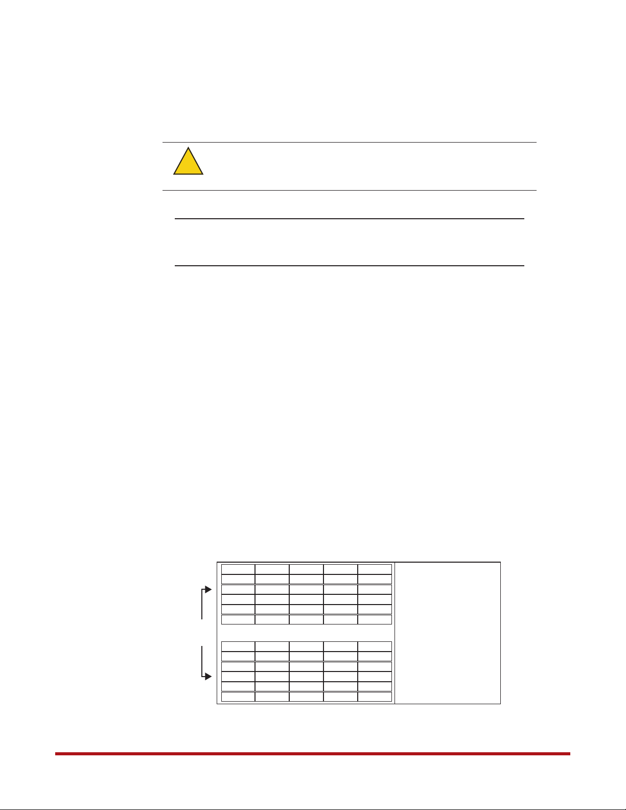
Figure 1 and Figure 2 illustrate the layout of disks in the SS7000 and SS8460 enclosures
respectively.
Figure 1. SS7000 Disk Module Layout
49
50
51
52
53
55
56
57
58
59
60
Front
of
Chassis
1
2
3
4
5
6 18304254
7
8
9
10
11
12
14
15
16
17
19
20
21
22
23
24
13
25
26
27
28
29
31
32
33
34
35
36
37
38
39
40
41
43
44
45
46
47
48
96-30051-001 Rev. D3 DDN SFA12K (SFA OS 2.3.1) Hardware Installation & Configuration Guide | 11
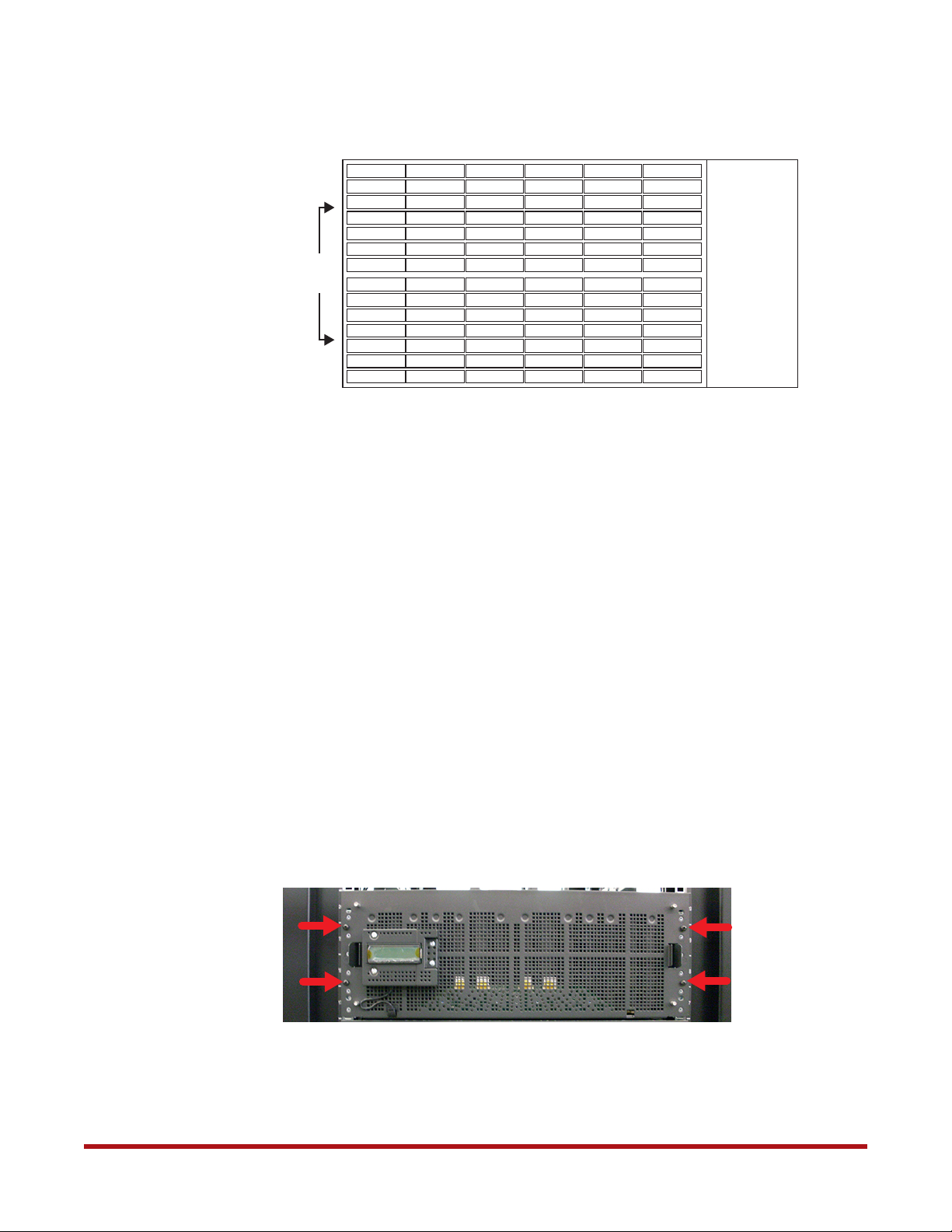
Figure 2. SS8460 Disk Module Layout
System Installation and Configuration
1 15 29 43 57
2 16 30 44 58
3 17 31 45 59
4 18 32 46 60
5 19 33 47 61
Front
of
Chassis
6 20 34 48 62
7 21 35 49 63
8 22 36 50 64
9 23 37 51 65
10 24 38 52 66
11 25 39 53 67
12 26 40 54 68
13 27 41 55 69 83
14 28 42 56 70 84
5.1 Blank Module Requirements
The SS7000 and SS8460 enclosures require blank modules to complete any partially
populated rows.
For example on the SS8460, if two rows are full, the third has six disk modules, and the other
rows are empty, then:
• The partially populated row #3 must have six blank modules
71
72
73
74
75
76
77
78
79
80
81
82
• The completely empty rows #4, #5, and #6 do not need any blank modules
Retain any unused blank modules for future use.
5.2 Racked Systems
If your system is already installed in the racks, there are four shipping screws installed on the
front panel of each disk enclosure to secure them for transit. These screws must be removed
or loosened before the enclosure can be pulled out for disk module installation.
For SS8460 enclosures, remove the four shipping screws as shown in Figure 3.
Figure 3. Shipping Screws on SS8460 Front Panel
For SS7000 enclosures, loosen the four shipping screws as shown in Figure 4.
96-30051-001 Rev. D3 DDN SFA12K (SFA OS 2.3.1) Hardware Installation & Configuration Guide | 12
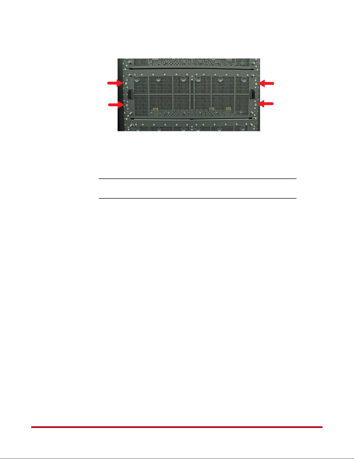
Figure 4. Shipping Screws on SS7000 Front Panel
5.3 Procedure
System Installation and Configuration
NOTE :
To install a disk module:
1. Slide the enclosure out from the rack by squeezing the tabs on both rack slides. Keep
pulling until the enclosure locks and you hear a clicking sound.
2. Open the enclosure covers.
3. Release the handle on the disk module.
4. Insert the module into a disk bay. Cam the disk module home. The camming foot on the
base of the module will engage into the slot in the enclosure.
5. When the module is fully inserted, close the handle.
6. After you have installed all the disk modules (and blank modules) in this enclosure,
close the enclosure covers and engage all cover latches.
7. Squeeze the tabs on both rack slides and push the enclosure back into the rack.
Refer to the respective StorageScaler 8460 and StorageScaler 7000 User
Guides if you need detailed instructions for disk module installation.
96-30051-001 Rev. D3 DDN SFA12K (SFA OS 2.3.1) Hardware Installation & Configuration Guide | 13
6. Couplet ICL/BBU/ATS Cabling
Using the figures referenced in Table 1:
Table 1. Controller Cabling Figures
System Installation and Configuration
Configuration with
BBU Model 5P1500GR
SFA12K-20
SFA12KXi/12KX/12K-40
SFA12KXE/12K-20E
Reference
Figure 6
Figure 8
Figure 10
Configuration with
BBU Model 1550
SFA12K-20
SFA12KXi/12KX/12K-40
SFA12KXE/12K-20E
Reference
Figure 7
Figure 9
Figure 11
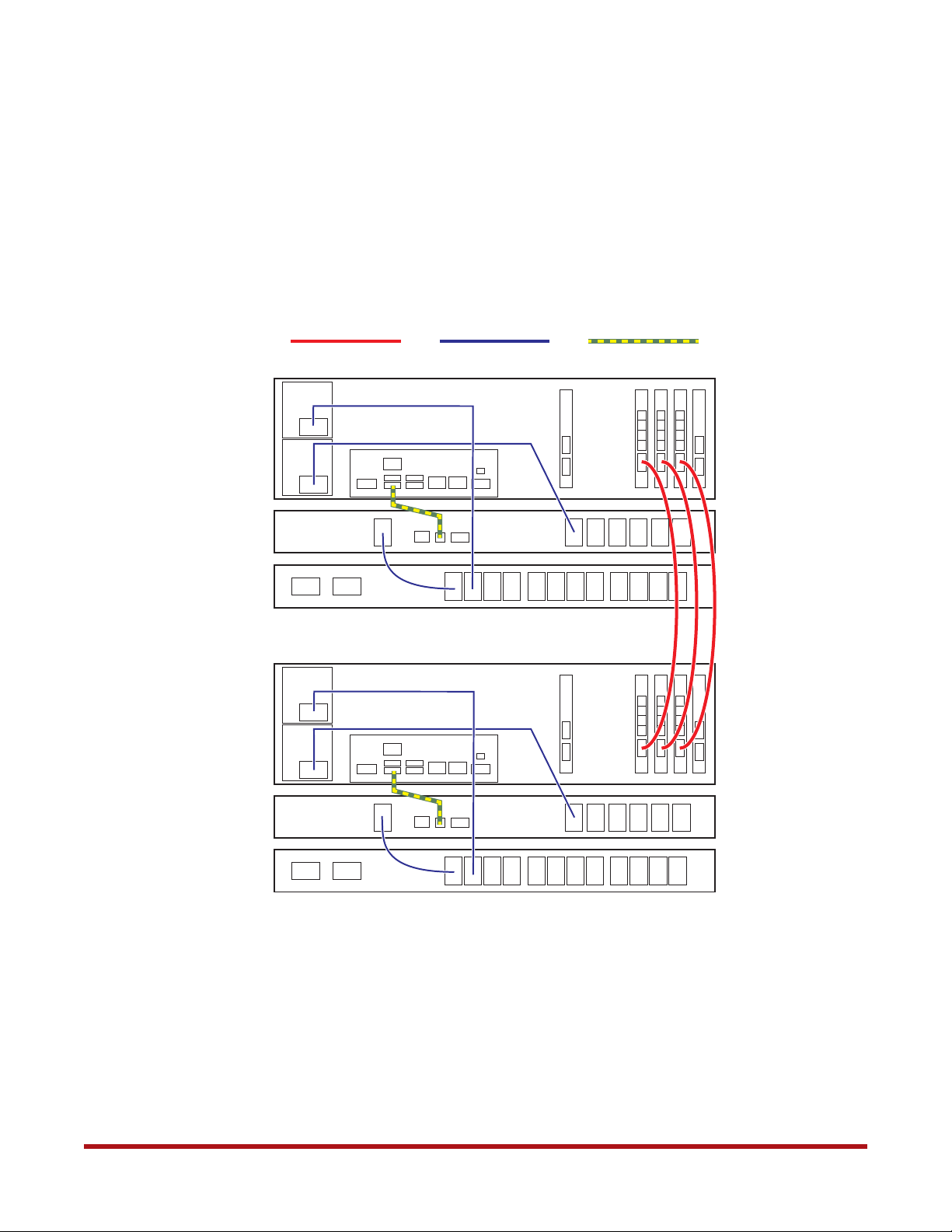
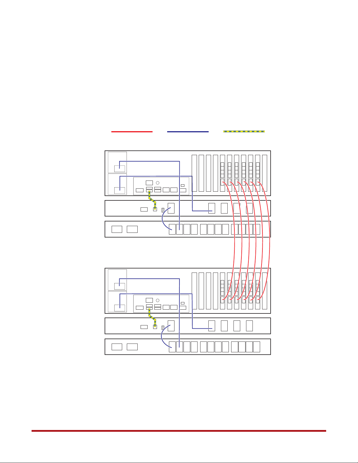
1. Connect the InfiniBand cables to the ICL ports on the two controllers as shown.
2. Connect the two power cables between the controller’s power supplies and its BBU
and ATS as shown.
3. Connect the USB cable between the controller and its BBU as shown.
4. For each ATS, connect the power cable to its BBU as shown.
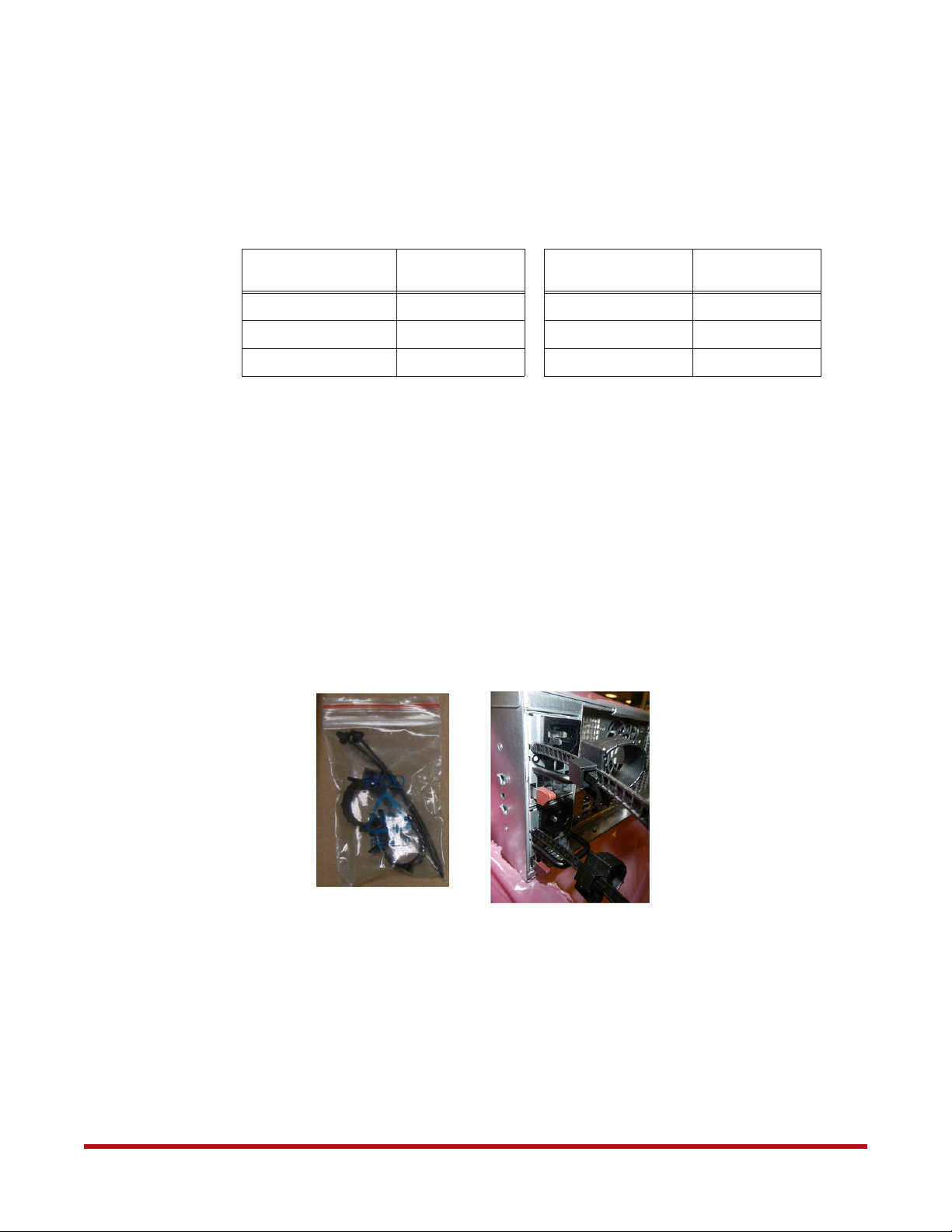
5. Attach a power cord retainer (included in the accessory kit) to each of the power
supply on the controllers as shown in Figure 5. Secure the power cord with the retainer.
Figure 5. Attach Power Cord Retainer on Controller Power Supply
96-30051-001 Rev. D3 DDN SFA12K (SFA OS 2.3.1) Hardware Installation & Configuration Guide | 14
System Installation and Configuration
Figure 6. Connecting SFA12K-20 Controllers to ATSs and BBU Model 5P1550GR
InfiniBand cable
Controller 0’s BBU
Model 5P1550GR
Controller 0’s ATS
Controller 0
Controller 1
AC power cable
USB cable
Controller 1’s BBU
Model 5P1550GR
Controller 1’s ATS
96-30051-001 Rev. D3 DDN SFA12K (SFA OS 2.3.1) Hardware Installation & Configuration Guide | 15
System Installation and Configuration
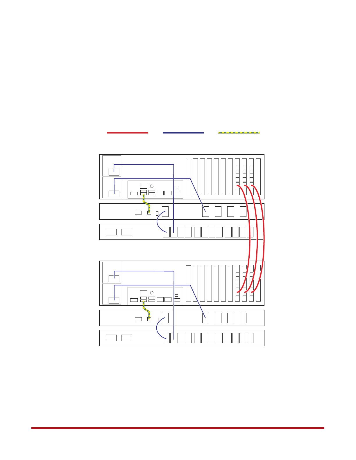
Figure 7. Connecting SFA12K-20 Controllers to ATSs and BBU Model 1550
InfiniBand cable
Controller 0’s BBU
Model 1550
Controller 0’s ATS
Controller 0
Controller 1
AC power cable
USB cable
Controller 1’s BBU
Model 1550
Controller 1’s ATS
96-30051-001 Rev. D3 DDN SFA12K (SFA OS 2.3.1) Hardware Installation & Configuration Guide | 16
System Installation and Configuration
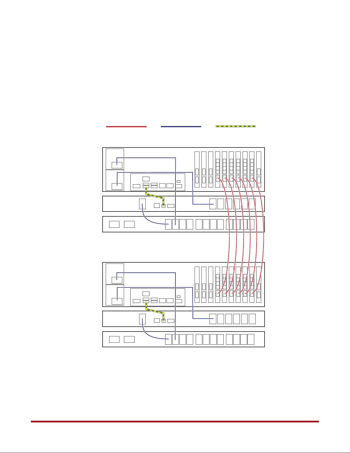
Figure 8. Connecting SFA12KXi/12KX/12K-40 Controllers to ATSs and BBU Model 5P1550GR
InfiniBand cable
Controller 0’s BBU
Model 5P1550GR
Controller 0’s ATS
Controller 0
Controller 1
AC power cable
USB cable
Controller 1’s BBU
Model 5P1550GR
Controller 1’s ATS
96-30051-001 Rev. D3 DDN SFA12K (SFA OS 2.3.1) Hardware Installation & Configuration Guide | 17
System Installation and Configuration
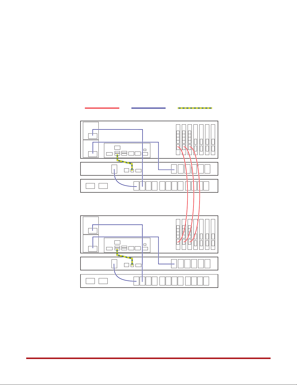
Figure 9. Connecting SFA12KXi/12KX/12K-40 Controllers to ATS and BBU Model 1550
InfiniBand cable
Controller 0’s BBU
Model 1550
Controller 0’s ATS
Controller 0
Controller 1
AC power cable
USB cable
Controller 1’s BBU
Model 1550
Controller 1’s ATS
96-30051-001 Rev. D3 DDN SFA12K (SFA OS 2.3.1) Hardware Installation & Configuration Guide | 18
System Installation and Configuration
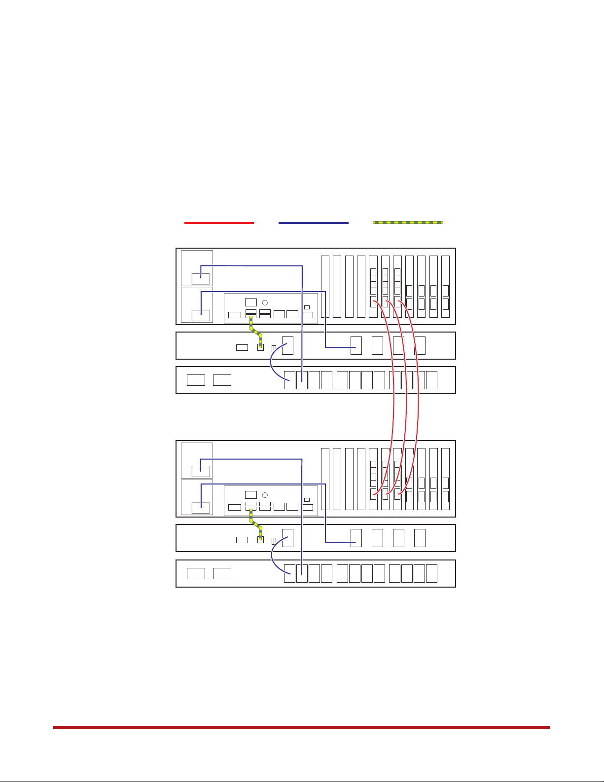
Figure 10. Connecting SFA12KXE/12K-20E Controllers to ATSs and BBU Model 5P1500GR
InfiniBand cable
Controller 0’s BBU
Model 5P1550GR
Controller 0’s ATS
Controller 0
Controller 1
AC power cable
USB cable
Controller 1’s BBU
Model 5P1550GR
Controller 1’s ATS
96-30051-001 Rev. D3 DDN SFA12K (SFA OS 2.3.1) Hardware Installation & Configuration Guide | 19
System Installation and Configuration
Figure 11. Connecting SFA12KXE/12K-20E Controllers to ATSs and BBU Model 1550
InfiniBand cable
Controller 0’s BBU
Model 1550
Controller 0’s ATS
Controller 0
Controller 1
AC power cable
USB cable
Controller 1’s BBU
Model 1550
Controller 1’s ATS
96-30051-001 Rev. D3 DDN SFA12K (SFA OS 2.3.1) Hardware Installation & Configuration Guide | 20

7. PDU Connections
1. Verify that the power switches on all the power distribution units (PDUs) are set to
OFF.
2. Connect the two ATSs’ Source A and Source B connectors to the PDUs. It is
recommended to connect the ATS’ Source A to the PDUs on the left side when viewed
from the back of the rack and connect Source B to the PDUs on the right side.
3. Connect the disk enclosures’ power supplies to the PDUs.
4. Connect the PDUs to your AC power source. For maximum redundancy, connect the
PDUs to different AC circuits.
Figure 12 illustrates an example for the PDU wiring. Actual wiring varies depending on the
PDU type, geography, and enclosure configurations.
System Installation and Configuration
96-30051-001 Rev. D3 DDN SFA12K (SFA OS 2.3.1) Hardware Installation & Configuration Guide | 21
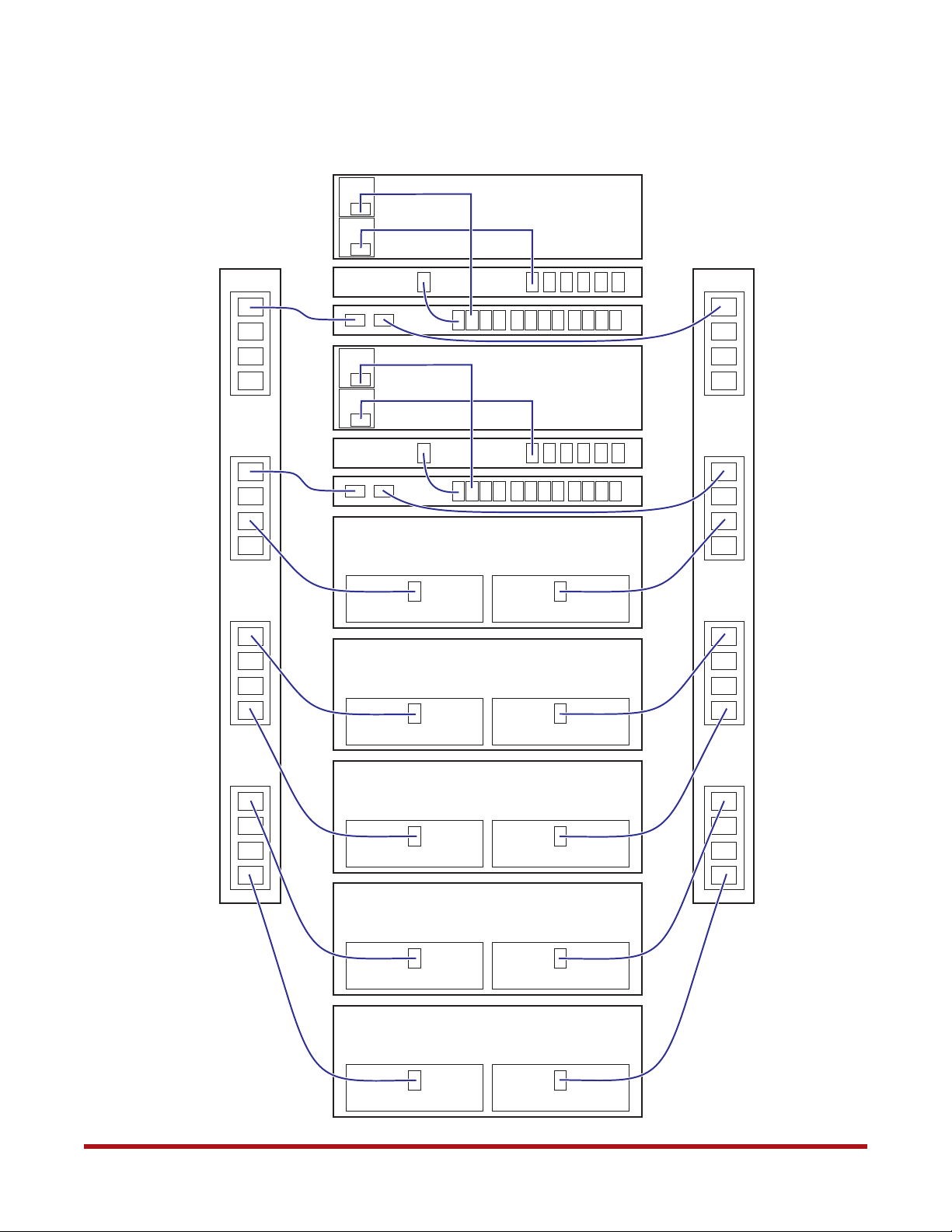
Figure 12. Example of PDU Wiring in Rack (Rear View)
Controller 0
System Installation and Configuration
PDU “Source A”
PDU “Source B”
BBU
ATS
Controller 1
BBU
ATS
Disk Enclosure
Disk Enclosure
Disk Enclosure
Disk Enclosure
Disk Enclosure
96-30051-001 Rev. D3 DDN SFA12K (SFA OS 2.3.1) Hardware Installation & Configuration Guide | 22
8. Configuring the ATSs
System Installation and Configuration
NOTE :
You must configure the ATSs’ Line VRMs and voltage transfer range
values for use at your site before powering up the SFA12K system.
8.1 Access the Web Interface
The SFA12K family dedicated ATSs are factory configured with a default IP address (see
Table 2). It is recommended that the ATS network interfaces be used only for initial setup.
Refer to the SFA OS User Guide for information on how to display the current network
interface settings on the ATS.
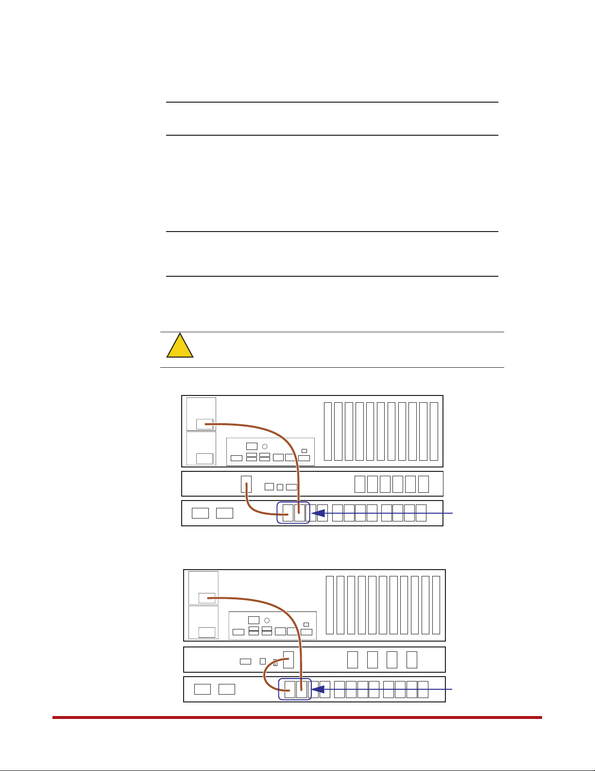
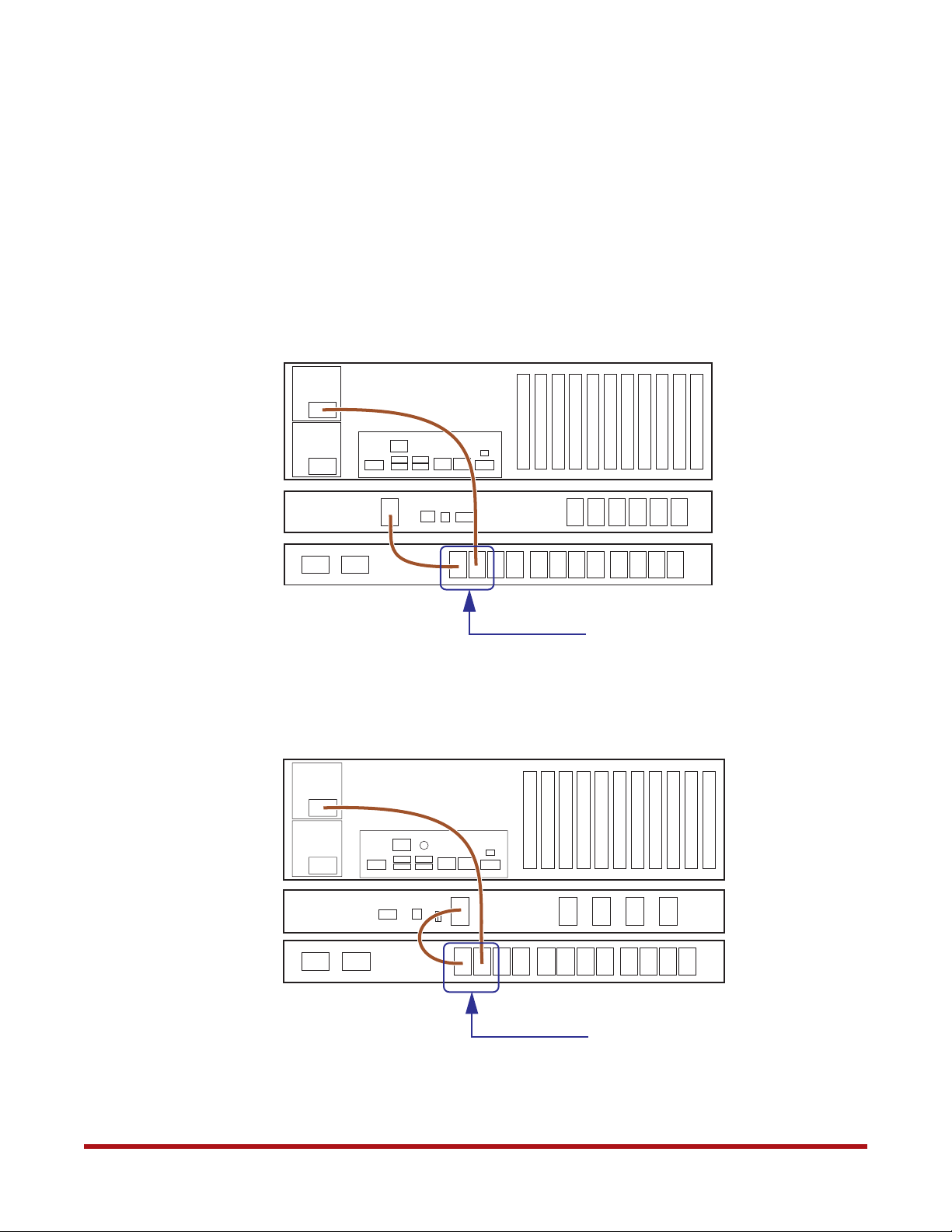
NOTE :
1. Temporarily unplug the controllers’ and BBUs’ power cables from the ATSs as shown
in Figure 13 and Figure 14.
!
Warning
It is recommended that the ATS remains disconnected from any
management networks after initial setup unless you plan on monitoring
it with event notifications as outlined in the SFA OS User Guide.
To ensure that the BBUs and controllers remain powered off during ATS
configuration, it is important to completely remove the power source.
Figure 13. Disconnect Power Cables from ATS (with BBU Model 5P1550GR)
Controller
BBU
Model 5P1550GR
ATS
Figure 14. Disconnect Power Cables from ATS (with BBU Model 1550)
Controller
BBU
Model 1550
ATS
96-30051-001 Rev. D3 DDN SFA12K (SFA OS 2.3.1) Hardware Installation & Configuration Guide | 23
Unplug
these two
power
connectors
Unplug
these two
power
connectors
System Installation and Configuration
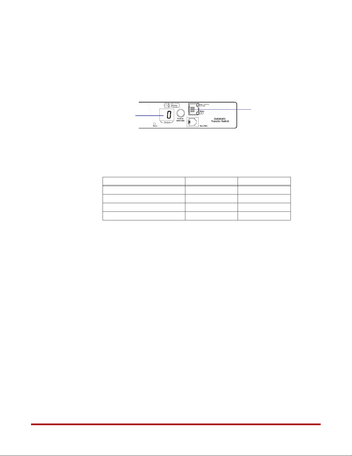
2. Turn on the ATSs by turning on the PDUs.
3. Ensure the ATS digital display shows “0”, indicating that it is ready.
4. Connect the Ethernet RJ-45 port on the ATS front panel directly to the network
interface of the computer that will be used to configure the ATS (Figure 15).
Figure 15. ATS Front Panel
Displays 0 when
bootup is complete
Ethernet port
5. Configure the IP address of the setup computer’s Ethernet port to an address in the
same subnet as the ATS you are connecting to (see Table 2). Refer to your operating
system reference documentation on how to configure the Ethernet port.
Table 2. Network Interface Settings for ATS Units
ATS 0 ATS 1
IP Address 10.0.0.3 10.0.1.3
Subnet Mask 255.255.255.0 255.255.255.0
Gateway 10.0.0.0 10.0.1.0
Configuring Computer IP Address 10.0.0.4 10.0.1.4
6. Open a browser to access the ATS by its IP address as shown in Table 2 above.
Use Mozilla Firefox version 1.x or higher. Use Microsoft Internet Explorer (IE) 5.5 or
higher on Windows operating systems.
7. Enter the user name and password. The default administrator user name is apc and
password is apc. Note that entries are case sensitive.
If you are unable to connect to the ATS Web interface, check the Ethernet cabling and retry.
8.2 Configure the Parameters
You must configure these parameters according to the nominal AC voltage at your site.
1. Log in to the ATS’s Web interface as described in Section 8.1 above.
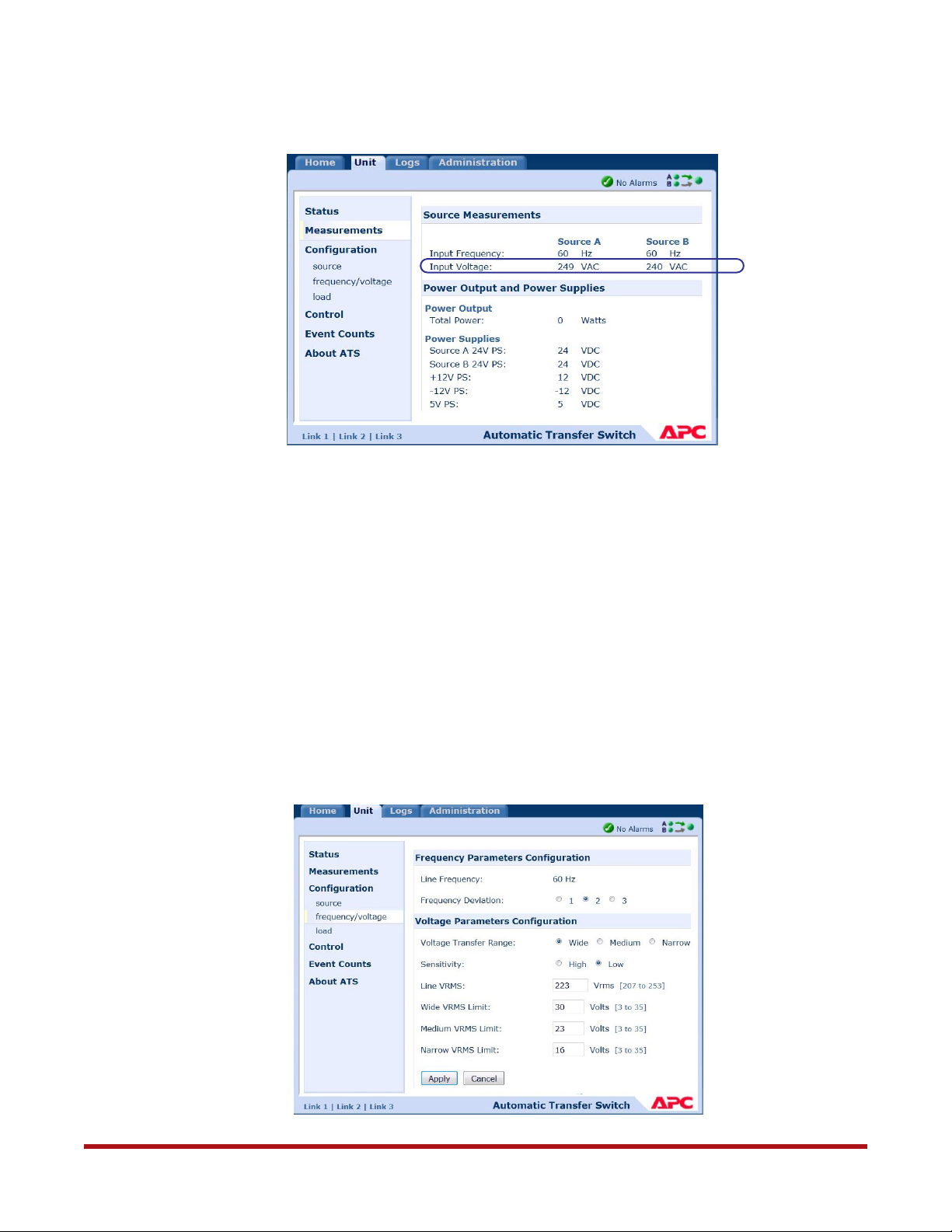
2. Determine the Source A and Source B voltages (Figure 16):
❖ Go to Unit tab
❖ Select Measurements
If the two AC Line voltages are within 10 volts, then compute their average and
proceed; otherwise, please contact DDN Support.
96-30051-001 Rev. D3 DDN SFA12K (SFA OS 2.3.1) Hardware Installation & Configuration Guide | 24
System Installation and Configuration
Figure 16. Measuring AC Line Voltages
3. Determine the nominal AC line voltage for the system. This is the value from the list
(200, 208, 220, 230, 240) that is closest to the average just computed.
For example, using the data in Figure 16:
Source A Voltage = 249
Source B Voltage = 240
Average AC Line voltage = (249 + 240)/2=244.5
Nominal AC line voltage = 240 because that is the closest number to 244.5 from the list.
Note: Use this value when setting the BBUs’ nominal voltage (as described later in
Section 13).
4. Set the ATS Line VRMS:
❖ Go to Unit tab
❖ Select Configuration > Frequency/voltage (Figure 17)
Figure 17. Configure Frequency/Voltage Parameters
96-30051-001 Rev. D3 DDN SFA12K (SFA OS 2.3.1) Hardware Installation & Configuration Guide | 25
System Installation and Configuration
❖ In the Voltage Transfer Range field, select “Wide”
❖ In the Sensitivity field, select “Low”
❖ In the Line VRMS field, enter the nominal AC line voltage value determined in
step 3 above
❖ In the Wide VRMS Limit field, enter “30”
❖ Click Apply to save the changes
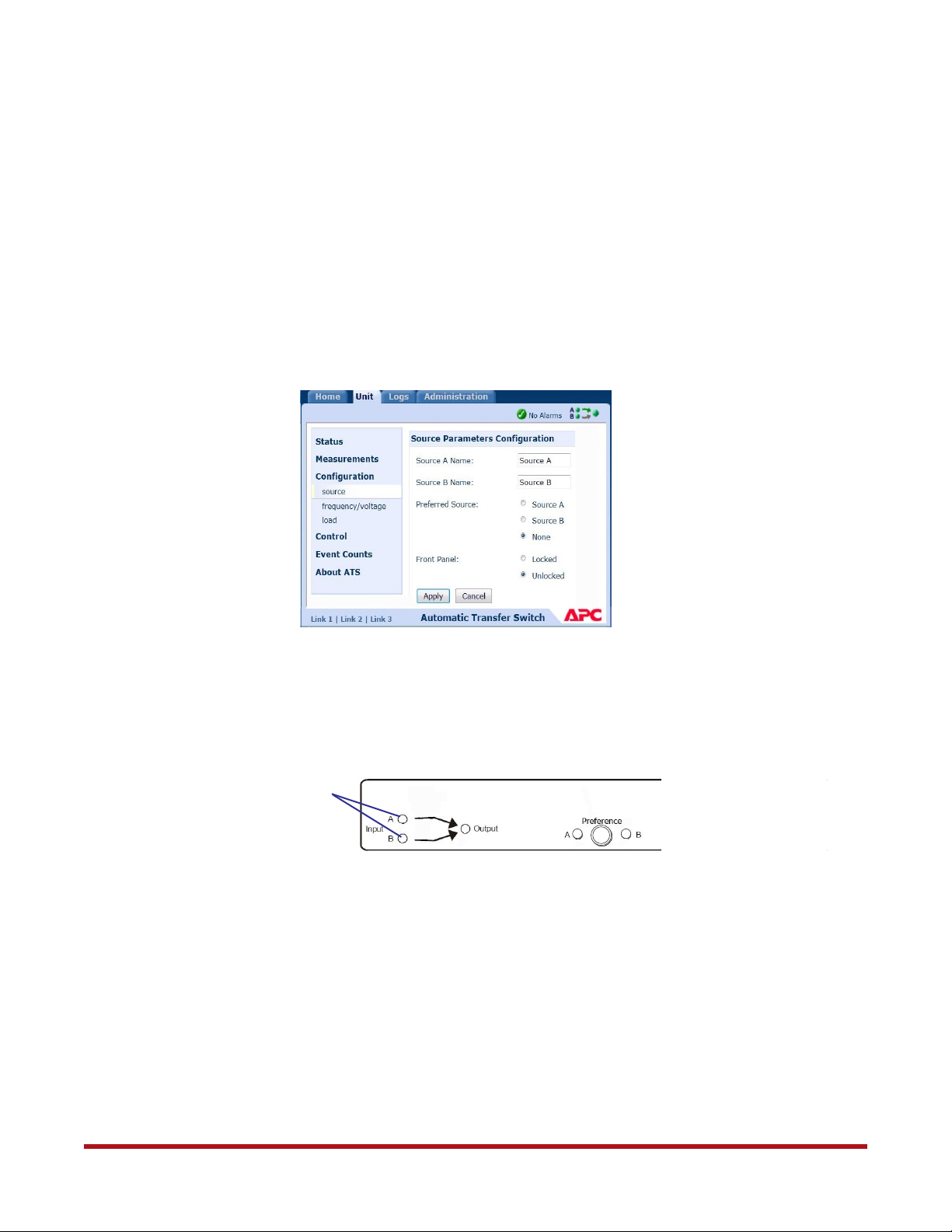
5. Select preferred source:
❖ Go to Unit tab
❖ Select Configuration - source (Figure 18)
Figure 18. Select Preferred Source
❖ In the Preferred Source field, select “None”
❖ Click Apply to save the changes
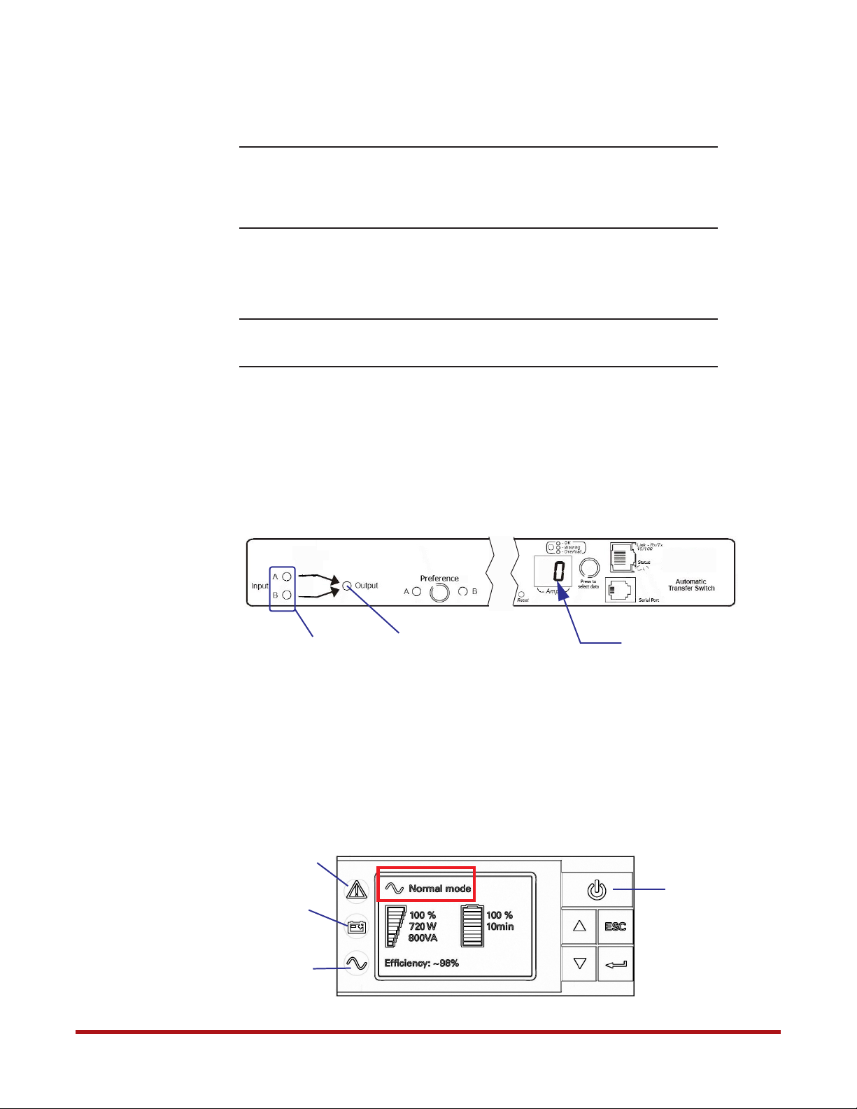
6. Verify that the Input A and B LEDs are both illuminated on the front panel (Figure 19).
Figure 19. ATS Front Panel
Input LEDs
7. Repeat steps 1 to 6 above on the other ATS.
8.3 Other Recommended Configurations
You may configure the date and time, administrator user name and password, and event
notifications for the ATS. Refer to the SFA OS User Guide (SFA12K ATS Recommended
Configurations) for more information.
96-30051-001 Rev. D3 DDN SFA12K (SFA OS 2.3.1) Hardware Installation & Configuration Guide | 26
8.4 Reconnect ATS
After you have configured both ATSs, it is now safe to connect them to the controllers and
BBUs.
1. Turn off the ATSs by turning off the PDUs.
2. Reconnect the power cords between the units as shown in Figure 20 and Figure 21.
Figure 20. Reconnect Power Cables from ATS (with BBU Model 5P1550GR)
BBU
Model 5P1550GR
System Installation and Configuration
Controller
ATS
Reconnect these two power connectors
Figure 21. Reconnect Power Cables to ATS (with BBU Model 1550)
Controller
BBU
Model 1550
ATS
Reconnect these two power connectors
96-30051-001 Rev. D3 DDN SFA12K (SFA OS 2.3.1) Hardware Installation & Configuration Guide | 27
9. Powering On the System
System Installation and Configuration
NOTE :
When the power is restored to the rack after a power interruption
(regardless of the subsystem being safely shut down), the controllers will
power up automatically. Please refer to the SFA OS User Guide (Powering
On After Subsystem Shutdown) for more information.
1. Turn on all the PDUs.
2. Turn on the power supply modules on all the disk enclosures.
NOTE :
ALL the disk enclosures must be powered up before powering on the
controllers.
3. On both ATSs (Figure 22):
❖ Verify that the unit displays “0” on the front panel, indicating that it is ready
❖ Verify that both Input A and B LEDs are ON, indicating that the ATS is operating
with full source redundancy
❖ Verify that the Output LED is ON, indicating that output voltage is available
Figure 22. ATS Front Panel
Input LEDs
Output LED
Displays “0”
4. Turn on both BBUs:
❖ For systems using Model 5P1550GR, go to step 5
❖ For systems using Model 1550, go to step 6
5. On both BBUs (Model 5P1550GR) (Figure 23):
❖ Press and hold the Power button on the front panel for at least 2 seconds to turn on
the unit. The LCD displays “UPS starting” then changes to “Normal mode.”
Figure 23. BBU Status LED Indicators on Front Panel (Model 5P1550GR)
Alarm
Indicator
(Red)
On Battery
Indicator
(Yellow)
Power On
Indicator
(Green)
Power Button
96-30051-001 Rev. D3 DDN SFA12K (SFA OS 2.3.1) Hardware Installation & Configuration Guide | 28
System Installation and Configuration
❖ Verify that the Power On indicator stays ON, indicating a successful power
application. If the On Battery indicator is ON, check the power input to the BBU.
❖ If the Alarm indicator is ON, do not proceed until all alarms are clear. Refer to the
BBU documentation for troubleshooting information.
❖ Continue from step 7
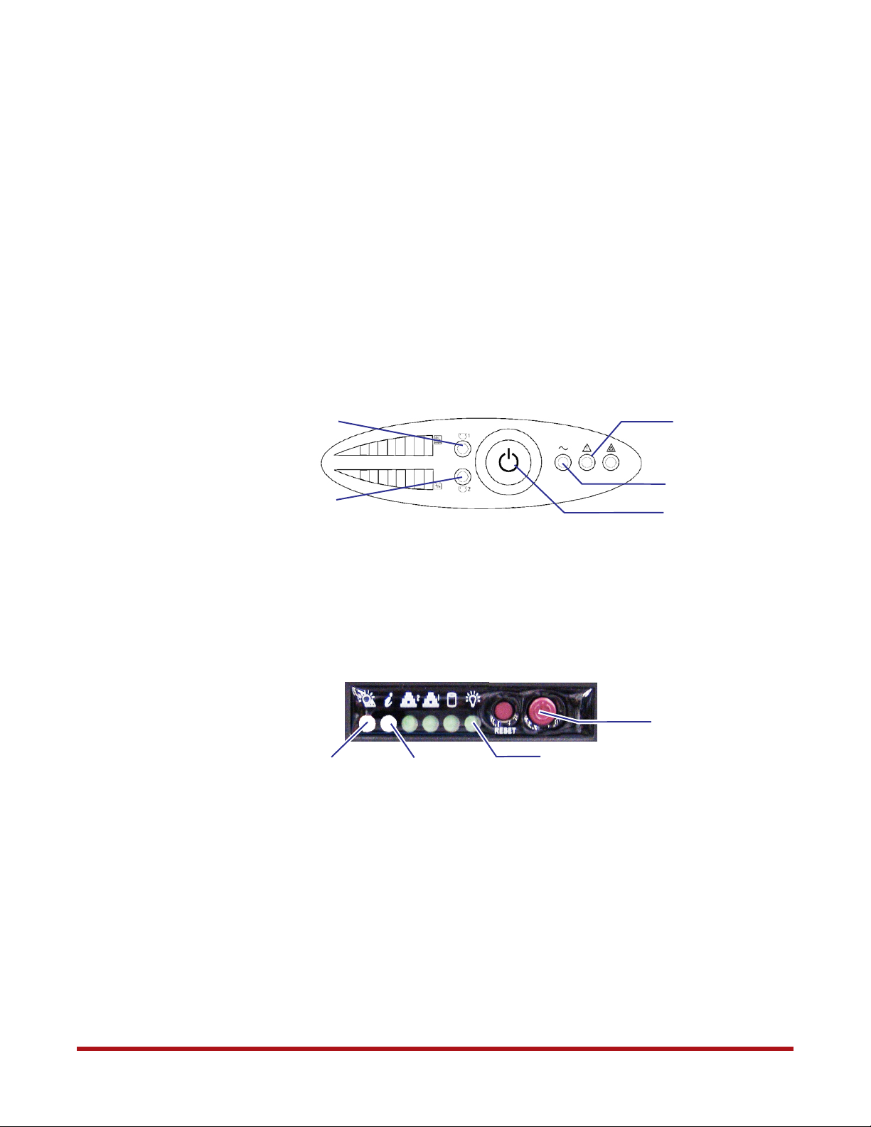
6. On both BBUs (Model 1550) (Figure 24):
❖ Press and hold the Power button on the front panel for 1 second to turn on the unit.
The buzzer beeps once and all the LEDs go ON momentarily.
❖ Verify that the Power LED and Load Protected LED stay ON, indicating a successful
power application. If the Degraded Operation LED is ON, check the power input to
the BBU.
❖ Verify that both Load Segment 1 and Load Segment 2 LEDs turn ON after 13 seconds
Figure 24. BBU Front Panel
Load Segment 1
Load Segment 2
7. Turn on both controllers:
❖ Remove the controller front bezel
❖ Press the power button once (Figure 25)
❖ Reinstall the front bezel
Figure 25. Controller Power Button and LEDs
PSU Fault LED (Off)
Enclosure Info (Off)
8. On both controllers (Figure 25):
Degraded
Operation LED
Load Protected LED
Power Button/LED
Power Button
Power Indicator (Green)
❖ Verify that the Power indicator is green
❖ The PSU Fault LED turns on during power up. Verify that it turns off after
13 seconds. If not, check the controller’s power supplies at the back.
❖ Verify that the Enclosure Info LED is off. If not, check the fan or power condition
according to the LED color:
• Solid amber: overheat
• Blink amber (1 Hz): fan fail
• Blink amber (0.25 Hz): power fail (PSU missing or AC missing)
• Blink blue: locate enclosure command received
96-30051-001 Rev. D3 DDN SFA12K (SFA OS 2.3.1) Hardware Installation & Configuration Guide | 29
System Installation and Configuration
9.1 Powering On using the Controller Power Button
If you turn on the controller by pressing only the controller power button, the controller will
automatically turn on its dedicated BBU once the controller is completely up and running.
Note that if you take this approach, you will not be able to verify that the BBU is on until that
point.
This feature is available:
• To ensure that the controller’s BBU is running even if you forget to turn it on
• To provide the ability to turn on the controller with a single push button
• To allow the controller and its BBU to be restarted remotely via IPMI
10. Serial Interface Setup & Accessing the CLUI
The SFA12K can be configured and administered either via serial connection (using the
supplied serial cable) or via Ethernet connection. However, in order to use the Ethernet
connection, it is first necessary to configure the network settings on each controller. This
can only be done using the serial interface as described in Section 11. The RS-232 console
can also be used to log the console output and to upgrade the BIOS/BMC firmware.
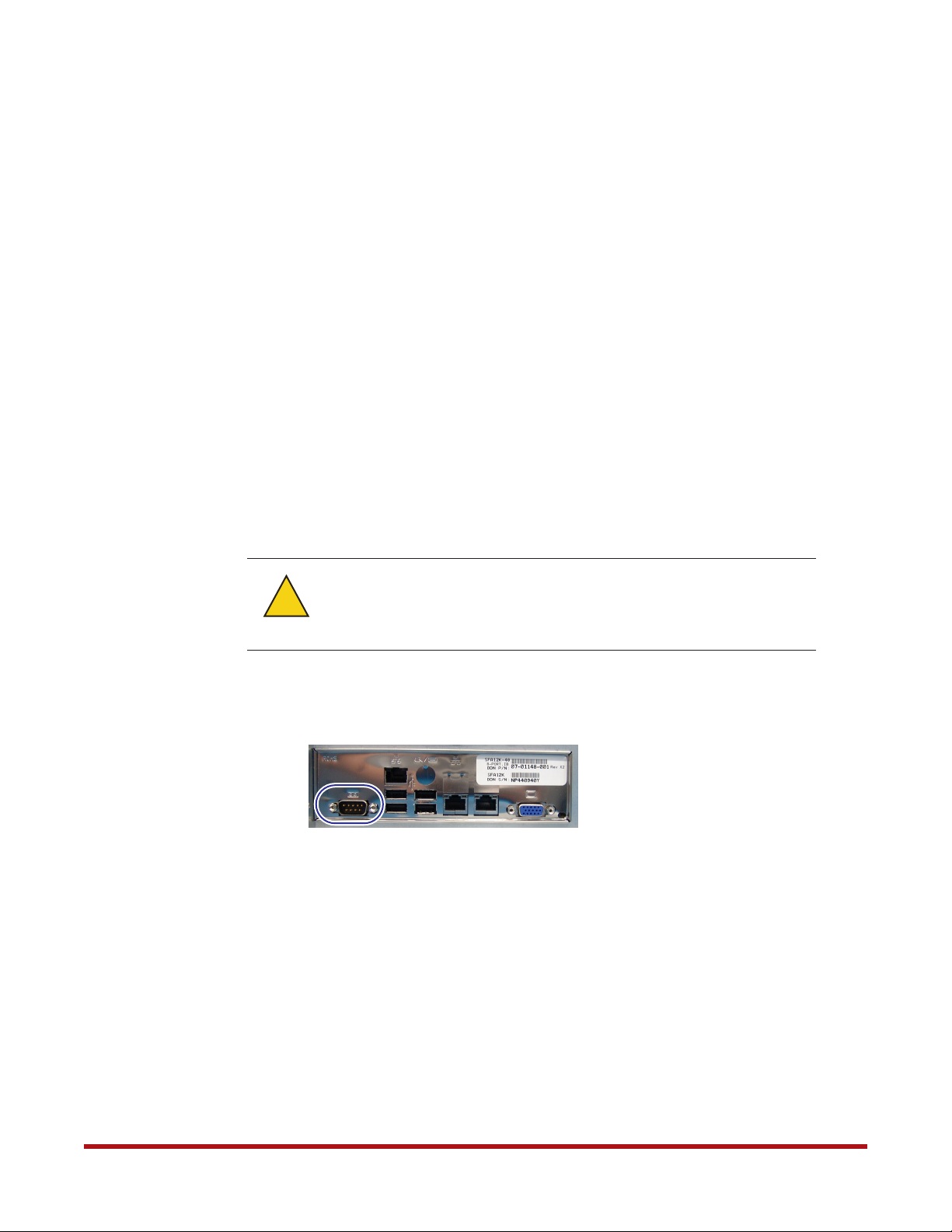
When the RS-232 null modem cable is attached to the controller, its
!
Warning
1. Connect a null modem cable between a PC and the RS-232 connector on the back of the
controller (Figure 26).
2. On the RS-232 console, load a serial console program (such as HyperTerminal,
minicom, PuTTY, or screen) and use the following settings for the serial connection:
❖ Bits per second: 115,200
❖ Data bits: 8
❖ Parity: None
❖ Stop bits: 1
❖ Flow control: None
corresponding opposite cable end must always be connected to a PC or
properly terminated. It should not be left unterminated or the operation
of the controller may be affected.
Figure 26. RS-232 Port on Controller
3. Once connected, press the <Enter> key to bring up the login prompt. Enter the user
name user and password user.
The CLUI commands are independent of case. Most of the keywords can be abbreviated and
most of the punctuations are optional.
96-30051-001 Rev. D3 DDN SFA12K (SFA OS 2.3.1) Hardware Installation & Configuration Guide | 30
 Loading...