

DataDirect Networks EF4024 FC Setup Manual

EF4024
Fibre Channel RAID System
Setup Guide
Document No.: 96-30065-001
Revision: A0

Important Information
Information in this document is subject to change without notice and does not represent a commitment
on the part of DataDirect Networks, Inc. No part of this manual may be reproduced or transmitted in any
form or by any means, electronic or mechanical, including photocopying and recording, for any purpose
other than the purchaser’s personal use without the written permission of DataDirect Networks, Inc.
© 2015 DataDirect Networks, Inc. All rights reserved.
DataDirect Networks, the DataDirect Networks logo, DDN, DirectMon, EXAScaler, GRIDScaler, HScaler,
IME, Infinite Memory Engine, Information in Motion, In-Storage Processing, NAS Scaler, NoFS,
ObjectAssure, ReACT, SFA, SFA 10000 Storage Fusion Architecture, SFA10K, SFA12K, SFX, Storage
Fusion Architecture, Storage Fusion Fabric, Storage Fusion Xcelerator, SwiftCluster, WOS, the WOS
logo are registered trademarks or trademarks of DataDirect Networks, Inc. All other brand and product
names are trademarks of their respective holders.
DataDirect Networks makes no warranties, express or implied, including without limitation the implied
warranties of merchantability and fitness for a particular purpose of any products or software.
DataDirect Networks does not warrant, guarantee or make any representations regarding the use or the
results of the use of any products or software in terms of correctness, accuracy, reliability, or otherwise.
The entire risk as to the results and performance of the product and software are assumed by you. The
exclusion of implied warranties is not permitted by some jurisdictions; this exclusion may not apply to
you.
In no event will DataDirect Network, their directors, officers, employees, or agents (collectively
DataDirect Networks) be liable to you for any consequential, incidental, or indirect damages, including
damages for loss of business profits, business interruption, loss of business information, and the like,
arising out of the use or inability to use any DataDirect product or software even if DataDirect Networks
has been advised of the possibility of such damages by you. Because some jurisdictions do not allow the
exclusion or limitation of liability for consequential or incidental damages, these limitations may not
apply to you. DataDirect Networks liability to you for actual damages from any cause whatsoever, and
regardless of the form of the action (whether in contract, tort including negligence, product liability or
otherwise), is limited to the sum you paid for the DataDirect product or software.
January 2015
96-30065-001 Rev. A0 DataDirect Networks EF4024 FC RAID System Setup Guide | 2

Preface
About this guide
This guide provides information about initial hardware setup for the DataDirect Networks
EF4024 Fibre Channel RAID system.
The EF4024 controller enclosures can optionally be cabled to the expansion enclosures for
adding storage.
Intended Audience
This guide is intended for storage system administrators.
Prerequisites
Prerequisites for installing and using this product include knowledge of:
• Servers and computer networks
• Network administration
• Storage system installation and configuration
• Storage area network (SAN) management and direct attach storage (DAS)
• Fibre Channel (FC), Serial Attached SCSI (SAS), and Ethernet protocols
Related Documentation
• EF4024 FC RAID System Quick Start Guide
• EF4024 FC RAID System RAIDar User Guide
• EF4024 CLUI Command Reference
96-30065-001 Rev. A0 DataDirect Networks EF4024 FC RAID System Setup Guide | 3

Table of Contents
Chapter 1 System Components . . . . . . . . . . . . . . . . . . . . . . . . . . . . . . . . . . . . . . . . . . . . . . . . . . . . . . . . . . . . . . . . . . . 9
1.1 Front Panel Components. . . . . . . . . . . . . . . . . . . . . . . . . . . . . . . . . . . . . . . . . . . . . . . . . . . . . . . . 10
1.1.1 Disk Drives. . . . . . . . . . . . . . . . . . . . . . . . . . . . . . . . . . . . . . . . . . . . . . . . . . . . . . . . . . . . 10
1.2 Controller Enclosure Rear Panel. . . . . . . . . . . . . . . . . . . . . . . . . . . . . . . . . . . . . . . . . . . . . . . . . 11
1.2.1 Controller Module . . . . . . . . . . . . . . . . . . . . . . . . . . . . . . . . . . . . . . . . . . . . . . . . . . . . 11
1.2.2 Power and Cooling Module . . . . . . . . . . . . . . . . . . . . . . . . . . . . . . . . . . . . . . . . . . . 11
1.3 Expansion Enclosure Rear Panel . . . . . . . . . . . . . . . . . . . . . . . . . . . . . . . . . . . . . . . . . . . . . . . . 12
1.3.1 Expansion Module . . . . . . . . . . . . . . . . . . . . . . . . . . . . . . . . . . . . . . . . . . . . . . . . . . . . 12
1.4 Cache . . . . . . . . . . . . . . . . . . . . . . . . . . . . . . . . . . . . . . . . . . . . . . . . . . . . . . . . . . . . . . . . . . . . . . . . . . . .12
1.5 CompactFlash . . . . . . . . . . . . . . . . . . . . . . . . . . . . . . . . . . . . . . . . . . . . . . . . . . . . . . . . . . . . . . . . . . .13
1.6 Supercapacitor Pack. . . . . . . . . . . . . . . . . . . . . . . . . . . . . . . . . . . . . . . . . . . . . . . . . . . . . . . . . . . . . 13
Chapter 2 Installing Enclosures . . . . . . . . . . . . . . . . . . . . . . . . . . . . . . . . . . . . . . . . . . . . . . . . . . . . . . . . . . . . . . . . . .14
2.1 Installation Checklist . . . . . . . . . . . . . . . . . . . . . . . . . . . . . . . . . . . . . . . . . . . . . . . . . . . . . . . . . . . .15
2.2 Connecting the Enclosures. . . . . . . . . . . . . . . . . . . . . . . . . . . . . . . . . . . . . . . . . . . . . . . . . . . . . .16
2.2.1 Cable Requirements . . . . . . . . . . . . . . . . . . . . . . . . . . . . . . . . . . . . . . . . . . . . . . . . . . 16
2.2.2 Enclosure Cabling Diagrams. . . . . . . . . . . . . . . . . . . . . . . . . . . . . . . . . . . . . . . . . . . 17
2.3 Powering On and Powering Off . . . . . . . . . . . . . . . . . . . . . . . . . . . . . . . . . . . . . . . . . . . . . . . . .18
2.3.1 Powering on the System . . . . . . . . . . . . . . . . . . . . . . . . . . . . . . . . . . . . . . . . . . . . . . 19
2.3.2 Powering off the System . . . . . . . . . . . . . . . . . . . . . . . . . . . . . . . . . . . . . . . . . . . . . . 20
Chapter 3 Connecting Hosts . . . . . . . . . . . . . . . . . . . . . . . . . . . . . . . . . . . . . . . . . . . . . . . . . . . . . . . . . . . . . . . . . . . . . .21
3.1 Host System Requirements . . . . . . . . . . . . . . . . . . . . . . . . . . . . . . . . . . . . . . . . . . . . . . . . . . . . .22
3.1.1 Cabling Considerations . . . . . . . . . . . . . . . . . . . . . . . . . . . . . . . . . . . . . . . . . . . . . . . 22
3.2 Connecting Enclosures to Hosts . . . . . . . . . . . . . . . . . . . . . . . . . . . . . . . . . . . . . . . . . . . . . . . . 22
3.2.1 Dual-Controller Configurations . . . . . . . . . . . . . . . . . . . . . . . . . . . . . . . . . . . . . . . . 23
3.2.2 Direct Attach Configurations . . . . . . . . . . . . . . . . . . . . . . . . . . . . . . . . . . . . . . . . . . 23
3.2.3 Switch Attach Configurations . . . . . . . . . . . . . . . . . . . . . . . . . . . . . . . . . . . . . . . . . 24
3.3 Connecting a Management Host on the Network. . . . . . . . . . . . . . . . . . . . . . . . . . . . . . 25
3.4 Updating firmware . . . . . . . . . . . . . . . . . . . . . . . . . . . . . . . . . . . . . . . . . . . . . . . . . . . . . . . . . . . . . . 25
3.5 Configuring Network Interfaces. . . . . . . . . . . . . . . . . . . . . . . . . . . . . . . . . . . . . . . . . . . . . . . . . 25
3.5.1 Using DHCP to Obtain Values. . . . . . . . . . . . . . . . . . . . . . . . . . . . . . . . . . . . . . . . . . 25
3.5.2 Manually Via CLI Port. . . . . . . . . . . . . . . . . . . . . . . . . . . . . . . . . . . . . . . . . . . . . . . . . . 26
Chapter 4 Basic Operation . . . . . . . . . . . . . . . . . . . . . . . . . . . . . . . . . . . . . . . . . . . . . . . . . . . . . . . . . . . . . . . . . . . . . . . .29
4.1 Accessing RAIDar . . . . . . . . . . . . . . . . . . . . . . . . . . . . . . . . . . . . . . . . . . . . . . . . . . . . . . . . . . . . . . . .30
4.2 Configuring and Provisioning the Storage System. . . . . . . . . . . . . . . . . . . . . . . . . . . . . 30
Chapter 5 Troubleshooting . . . . . . . . . . . . . . . . . . . . . . . . . . . . . . . . . . . . . . . . . . . . . . . . . . . . . . . . . . . . . . . . . . . . . . . 31
5.1 USB CLI Port Connection . . . . . . . . . . . . . . . . . . . . . . . . . . . . . . . . . . . . . . . . . . . . . . . . . . . . . . . . 32
5.2 Fault Isolation Methodology . . . . . . . . . . . . . . . . . . . . . . . . . . . . . . . . . . . . . . . . . . . . . . . . . . . . 32
5.2.1 Basic Steps. . . . . . . . . . . . . . . . . . . . . . . . . . . . . . . . . . . . . . . . . . . . . . . . . . . . . . . . . . . . 32
5.2.2 Options Available for Performing Basic Steps . . . . . . . . . . . . . . . . . . . . . . . . . . 32
96-30065-001 Rev. A0 DataDirect Networks EF4024 FC RAID System Setup Guide | 4

Table of Contents
5.2.2.1 Via RAIDar . . . . . . . . . . . . . . . . . . . . . . . . . . . . . . . . . . . . . . . . . . . . . . . . . . . . . . . . . . . . . . . .33
5.2.2.2 Via CLUI. . . . . . . . . . . . . . . . . . . . . . . . . . . . . . . . . . . . . . . . . . . . . . . . . . . . . . . . . . . . . . . . . . .33
5.2.2.3 Monitor Event Notification . . . . . . . . . . . . . . . . . . . . . . . . . . . . . . . . . . . . . . . . . . . . . . 33
5.2.2.4 View the Enclosure LEDs. . . . . . . . . . . . . . . . . . . . . . . . . . . . . . . . . . . . . . . . . . . . . . . . .33
5.2.3 Performing Basic Steps. . . . . . . . . . . . . . . . . . . . . . . . . . . . . . . . . . . . . . . . . . . . . . . . 33
5.2.3.1 Gather Fault Information . . . . . . . . . . . . . . . . . . . . . . . . . . . . . . . . . . . . . . . . . . . . . . . . 33
5.2.3.2 Determine Where the Fault is Occurring . . . . . . . . . . . . . . . . . . . . . . . . . . . . . . . .34
5.2.3.3 Review the Event Logs. . . . . . . . . . . . . . . . . . . . . . . . . . . . . . . . . . . . . . . . . . . . . . . . . . . 34
5.2.3.4 Isolate the Fault . . . . . . . . . . . . . . . . . . . . . . . . . . . . . . . . . . . . . . . . . . . . . . . . . . . . . . . . . .34
5.2.4 Enclosure Does Not Initialize . . . . . . . . . . . . . . . . . . . . . . . . . . . . . . . . . . . . . . . . . . 34
5.2.5 Correcting Enclosure IDs . . . . . . . . . . . . . . . . . . . . . . . . . . . . . . . . . . . . . . . . . . . . . . 35
5.3 Stopping I/O . . . . . . . . . . . . . . . . . . . . . . . . . . . . . . . . . . . . . . . . . . . . . . . . . . . . . . . . . . . . . . . . . . . . . 35
5.4 Diagnostic Steps. . . . . . . . . . . . . . . . . . . . . . . . . . . . . . . . . . . . . . . . . . . . . . . . . . . . . . . . . . . . . . . . .36
5.5 Isolating a Host-Side Connection Fault . . . . . . . . . . . . . . . . . . . . . . . . . . . . . . . . . . . . . . . . . 39
5.6 Isolating a Controller Module Expansion Port Connection Fault . . . . . . . . . . . . . .40
5.7 Resolving Voltage and Temperature Warnings. . . . . . . . . . . . . . . . . . . . . . . . . . . . . . . . . 42
5.7.1 Sensor Locations. . . . . . . . . . . . . . . . . . . . . . . . . . . . . . . . . . . . . . . . . . . . . . . . . . . . . . 42
5.7.2 Power Supply Sensors. . . . . . . . . . . . . . . . . . . . . . . . . . . . . . . . . . . . . . . . . . . . . . . . . 42
5.7.3 Cooling Fan Sensors . . . . . . . . . . . . . . . . . . . . . . . . . . . . . . . . . . . . . . . . . . . . . . . . . . 42
5.7.4 Temperature Sensors . . . . . . . . . . . . . . . . . . . . . . . . . . . . . . . . . . . . . . . . . . . . . . . . . 43
5.7.5 Power Supply Module Voltage Sensors . . . . . . . . . . . . . . . . . . . . . . . . . . . . . . . . 44
Appendix A LED Descriptions . . . . . . . . . . . . . . . . . . . . . . . . . . . . . . . . . . . . . . . . . . . . . . . . . . . . . . . . . . . . . . . . . . . . . . .45
A.1 Enclosure Bezels . . . . . . . . . . . . . . . . . . . . . . . . . . . . . . . . . . . . . . . . . . . . . . . . . . . . . . . . . . . . . . 46
A.1.1 Installing Enclosure Bezel . . . . . . . . . . . . . . . . . . . . . . . . . . . . . . . . . . . . . . . . . . . . . . . . . 46
A.1.2 Removing Enclosure Bezel . . . . . . . . . . . . . . . . . . . . . . . . . . . . . . . . . . . . . . . . . . . . . . . .46
A.2 Enclosure Front Panel LEDs . . . . . . . . . . . . . . . . . . . . . . . . . . . . . . . . . . . . . . . . . . . . . . . . . . 47
A.3 Disk Drive LEDs . . . . . . . . . . . . . . . . . . . . . . . . . . . . . . . . . . . . . . . . . . . . . . . . . . . . . . . . . . . . . . . 48
A.4 Controller Module . . . . . . . . . . . . . . . . . . . . . . . . . . . . . . . . . . . . . . . . . . . . . . . . . . . . . . . . . . . . 50
A.4.1 Cache Status LED Details . . . . . . . . . . . . . . . . . . . . . . . . . . . . . . . . . . . . . . . . . . . . . . . . . . 51
A.5 Power and Cooling Module LEDs . . . . . . . . . . . . . . . . . . . . . . . . . . . . . . . . . . . . . . . . . . . . 52
A.6 LEDs on Expansion Module . . . . . . . . . . . . . . . . . . . . . . . . . . . . . . . . . . . . . . . . . . . . . . . . . . 53
Appendix B Environmental Requirements & Specifications . . . . . . . . . . . . . . . . . . . . . . . . . . . . . . . . . . . 54
B.1 Safety Requirements . . . . . . . . . . . . . . . . . . . . . . . . . . . . . . . . . . . . . . . . . . . . . . . . . . . . . . . . . 55
B.2 Site Requirements and Guidelines . . . . . . . . . . . . . . . . . . . . . . . . . . . . . . . . . . . . . . . . . . . 55
B.2.1 Site Wiring and AC Power Requirements . . . . . . . . . . . . . . . . . . . . . . . . . . . . . . . . . 55
B.2.2 Weight and Placement Guidelines . . . . . . . . . . . . . . . . . . . . . . . . . . . . . . . . . . . . . . . .56
B.2.3 Electrical Guidelines . . . . . . . . . . . . . . . . . . . . . . . . . . . . . . . . . . . . . . . . . . . . . . . . . . . . . . .56
B.2.4 Ventilation Requirements . . . . . . . . . . . . . . . . . . . . . . . . . . . . . . . . . . . . . . . . . . . . . . . . . 56
B.2.5 Cabling Requirements . . . . . . . . . . . . . . . . . . . . . . . . . . . . . . . . . . . . . . . . . . . . . . . . . . . .57
B.3 Physical Requirements . . . . . . . . . . . . . . . . . . . . . . . . . . . . . . . . . . . . . . . . . . . . . . . . . . . . . . . 57
B.4 Environmental Requirements . . . . . . . . . . . . . . . . . . . . . . . . . . . . . . . . . . . . . . . . . . . . . . . . 58
B.5 Electrical Requirements . . . . . . . . . . . . . . . . . . . . . . . . . . . . . . . . . . . . . . . . . . . . . . . . . . . . . . 59
B.5.1 Site wiring and Power Requirements . . . . . . . . . . . . . . . . . . . . . . . . . . . . . . . . . . . . . 59
B.5.2 Power Cable Requirements . . . . . . . . . . . . . . . . . . . . . . . . . . . . . . . . . . . . . . . . . . . . . . .59
B.6 Management Host Requirements. . . . . . . . . . . . . . . . . . . . . . . . . . . . . . . . . . . . . . . . . . . . 59
96-30065-001 Rev. A0 DataDirect Networks EF4024 FC RAID System Setup Guide | 5

Table of Contents
Appendix C Electrostatic Discharge . . . . . . . . . . . . . . . . . . . . . . . . . . . . . . . . . . . . . . . . . . . . . . . . . . . . . . . . . . . . . . . .60
C.1 Preventing Electrostatic Discharge . . . . . . . . . . . . . . . . . . . . . . . . . . . . . . . . . . . . . . . . . . 61
C.2 Grounding Methods . . . . . . . . . . . . . . . . . . . . . . . . . . . . . . . . . . . . . . . . . . . . . . . . . . . . . . . . . . 61
Appendix D USB Device Connection . . . . . . . . . . . . . . . . . . . . . . . . . . . . . . . . . . . . . . . . . . . . . . . . . . . . . . . . . . . . . . . 62
D.1 USB Ports on Controller Modules . . . . . . . . . . . . . . . . . . . . . . . . . . . . . . . . . . . . . . . . . . . . 63
D.1.1 USB CLI Port . . . . . . . . . . . . . . . . . . . . . . . . . . . . . . . . . . . . . . . . . . . . . . . . . . . . . . . . . . . . . . .63
D.1.2 Emulated Serial Port . . . . . . . . . . . . . . . . . . . . . . . . . . . . . . . . . . . . . . . . . . . . . . . . . . . . . . .63
D.1.3 Supported Host Applications . . . . . . . . . . . . . . . . . . . . . . . . . . . . . . . . . . . . . . . . . . . . .64
D.1.4 Command Line User Interface . . . . . . . . . . . . . . . . . . . . . . . . . . . . . . . . . . . . . . . . . . . . 64
D.2 Device Driver/Special Operation Mode . . . . . . . . . . . . . . . . . . . . . . . . . . . . . . . . . . . . . . 64
D.2.1 Microsoft Windows . . . . . . . . . . . . . . . . . . . . . . . . . . . . . . . . . . . . . . . . . . . . . . . . . . . . . . . . 64
D.2.2 Linux . . . . . . . . . . . . . . . . . . . . . . . . . . . . . . . . . . . . . . . . . . . . . . . . . . . . . . . . . . . . . . . . . . . . . . . 64
D.3 Known Issues on Windows . . . . . . . . . . . . . . . . . . . . . . . . . . . . . . . . . . . . . . . . . . . . . . . . . . . 65
Appendix E SFP Option for CNC Ports . . . . . . . . . . . . . . . . . . . . . . . . . . . . . . . . . . . . . . . . . . . . . . . . . . . . . . . . . . . . . 66
E.1 Locate the SFP transceivers . . . . . . . . . . . . . . . . . . . . . . . . . . . . . . . . . . . . . . . . . . . . . . . . . . 67
E.2 Install an SFP transceiver . . . . . . . . . . . . . . . . . . . . . . . . . . . . . . . . . . . . . . . . . . . . . . . . . . . . . 67
E.3 Verify Component Operation . . . . . . . . . . . . . . . . . . . . . . . . . . . . . . . . . . . . . . . . . . . . . . . . 68
Index . . . . . . . . . . . . . . . . . . . . . . . . . . . . . . . . . . . . . . . . . . . . . . . . . . . . . . . . . . . . . . . . . . . . . . . . . . . . . . . . . . . . . . . . . . . . . . . . . . . . . . . . . . . . . . . . . . 69
Contacting Technical Support . . . . . . . . . . . . . . . . . . . . . . . . . . . . . . . . . . . . . . . . . . . . . . . . . . . . . . . . . . . . . . . . . . . . . . . . . . . . . . . . . . . .72
96-30065-001 Rev. A0 DataDirect Networks EF4024 FC RAID System Setup Guide | 6

List of Figures
Figure 1. Enclosure Front with Bezel Installed . . . . . . . . . . . . . . . . . . . . . . . . . . . . . . . . . . . . . . . . . . . . . . 10
Figure 2. LEDs on Front Panel . . . . . . . . . . . . . . . . . . . . . . . . . . . . . . . . . . . . . . . . . . . . . . . . . . . . . . . . . . . . . . 10
Figure 3. Controller Enclosure Rear Panel. . . . . . . . . . . . . . . . . . . . . . . . . . . . . . . . . . . . . . . . . . . . . . . . . . . 11
Figure 4. Controller Module. . . . . . . . . . . . . . . . . . . . . . . . . . . . . . . . . . . . . . . . . . . . . . . . . . . . . . . . . . . . . . . . 11
Figure 5. Expansion Enclosure Rear Panel . . . . . . . . . . . . . . . . . . . . . . . . . . . . . . . . . . . . . . . . . . . . . . . . . . 12
Figure 6. Expansion Module . . . . . . . . . . . . . . . . . . . . . . . . . . . . . . . . . . . . . . . . . . . . . . . . . . . . . . . . . . . . . . . 12
Figure 7. CompactFlash Card in Controller Module . . . . . . . . . . . . . . . . . . . . . . . . . . . . . . . . . . . . . . . . . 13
Figure 8. Connecting One Expansion Enclosure to Controller Enclosure . . . . . . . . . . . . . . . . . . . . . 17
Figure 9. Connecting Three Expansion Enclosures (Straight-Through Cabling). . . . . . . . . . . . . . . 17
Figure 10. Connecting Three Expansion Enclosures (Reverse Cabling) . . . . . . . . . . . . . . . . . . . . . . . . 18
Figure 11. Power Cord Connector on Power Supply Modules. . . . . . . . . . . . . . . . . . . . . . . . . . . . . . . . . 19
Figure 12. Connect Power Cords to Rack Power Source . . . . . . . . . . . . . . . . . . . . . . . . . . . . . . . . . . . . . . 19
Figure 13. Connecting Hosts: Direct Attach - One Server/One HBA/Dual Path . . . . . . . . . . . . . . . . . 24
Figure 14. Connecting Hosts: Direct Attach - Two Servers/One HBA/Dual Path . . . . . . . . . . . . . . . . 24
Figure 15. Connecting Hosts: Switch Attach - Two Servers/Two Switches . . . . . . . . . . . . . . . . . . . . . 24
Figure 16. Connecting USB Cable to CLI Port on Controller Module. . . . . . . . . . . . . . . . . . . . . . . . . . . 26
Figure 17. Enclosure Bezel . . . . . . . . . . . . . . . . . . . . . . . . . . . . . . . . . . . . . . . . . . . . . . . . . . . . . . . . . . . . . . . . . . 46
Figure 18. Aligning Bezel with Chassis. . . . . . . . . . . . . . . . . . . . . . . . . . . . . . . . . . . . . . . . . . . . . . . . . . . . . . . 46
Figure 19. Enclosure Front Panel LEDs and Drive Slot Numbers. . . . . . . . . . . . . . . . . . . . . . . . . . . . . . . 47
Figure 20. Disk Module LEDs . . . . . . . . . . . . . . . . . . . . . . . . . . . . . . . . . . . . . . . . . . . . . . . . . . . . . . . . . . . . . . . . 48
Figure 21. LEDs on Controller Module . . . . . . . . . . . . . . . . . . . . . . . . . . . . . . . . . . . . . . . . . . . . . . . . . . . . . . . 50
Figure 22. LEDs on Power and Cooling Module . . . . . . . . . . . . . . . . . . . . . . . . . . . . . . . . . . . . . . . . . . . . . . 52
Figure 23. LEDs on Expansion Module. . . . . . . . . . . . . . . . . . . . . . . . . . . . . . . . . . . . . . . . . . . . . . . . . . . . . . . 53
Figure 24. Rackmount Enclosure Dimensions . . . . . . . . . . . . . . . . . . . . . . . . . . . . . . . . . . . . . . . . . . . . . . . . 57
Figure 25. Connecting USB Cable to CLI Port. . . . . . . . . . . . . . . . . . . . . . . . . . . . . . . . . . . . . . . . . . . . . . . . . 63
Figure 26. Installing a Qualified SFP Option. . . . . . . . . . . . . . . . . . . . . . . . . . . . . . . . . . . . . . . . . . . . . . . . . . 67
96-30065-001 Rev. A0 DataDirect Networks EF4024 FC RAID System Setup Guide | 7

List of Tables
Table 1. Installation Checklist . . . . . . . . . . . . . . . . . . . . . . . . . . . . . . . . . . . . . . . . . . . . . . . . . . . . . . . . . . . . . 15
Table 2. Terminal Emulator Display Settings . . . . . . . . . . . . . . . . . . . . . . . . . . . . . . . . . . . . . . . . . . . . . . . 27
Table 3. Terminal Emulator Connection Settings. . . . . . . . . . . . . . . . . . . . . . . . . . . . . . . . . . . . . . . . . . . 27
Table 4. Enclosure Front Panel LED Descriptions. . . . . . . . . . . . . . . . . . . . . . . . . . . . . . . . . . . . . . . . . . . 47
Table 5. Disk Module LED Description . . . . . . . . . . . . . . . . . . . . . . . . . . . . . . . . . . . . . . . . . . . . . . . . . . . . . 48
Table 6. Disk Module LED Behavior. . . . . . . . . . . . . . . . . . . . . . . . . . . . . . . . . . . . . . . . . . . . . . . . . . . . . . . . 49
Table 7. Vdisk LED Behavior. . . . . . . . . . . . . . . . . . . . . . . . . . . . . . . . . . . . . . . . . . . . . . . . . . . . . . . . . . . . . . . 49
Table 8. Controller Module LED Descriptions . . . . . . . . . . . . . . . . . . . . . . . . . . . . . . . . . . . . . . . . . . . . . . 50
Table 9. Power and Cooling Module LED Descriptions . . . . . . . . . . . . . . . . . . . . . . . . . . . . . . . . . . . . . 52
Table 10. Expansion Enclosure I/O Module LED Descriptions . . . . . . . . . . . . . . . . . . . . . . . . . . . . . . . . 53
Table 11. Power Requirements - AC Input . . . . . . . . . . . . . . . . . . . . . . . . . . . . . . . . . . . . . . . . . . . . . . . . . . 55
Table 12. Rackmount Controller Enclosure Weights . . . . . . . . . . . . . . . . . . . . . . . . . . . . . . . . . . . . . . . . . 58
Table 13. Supported Terminal Emulator Applications . . . . . . . . . . . . . . . . . . . . . . . . . . . . . . . . . . . . . . . 64
Table 14. USB Vendor and Product Identification Codes. . . . . . . . . . . . . . . . . . . . . . . . . . . . . . . . . . . . . 64
96-30065-001 Rev. A0 DataDirect Networks EF4024 FC RAID System Setup Guide | 8

Chapter 1
1.0System Components
96-30065-001 Rev. A0 DataDirect Networks EF4024 FC RAID System Setup Guide | 9
The EF4024 FC RAID system is a 2U enclosure that supports 24 2.5" small form factor (SFF)
disks. It can be used as either a controller enclosure or expansion enclosure.
Each controller enclosure includes two controller modules while the expansion enclosures
include dual expansion I/O modules (IOMs). Both types of enclosure are equipped with two
redundant power and cooling modules.
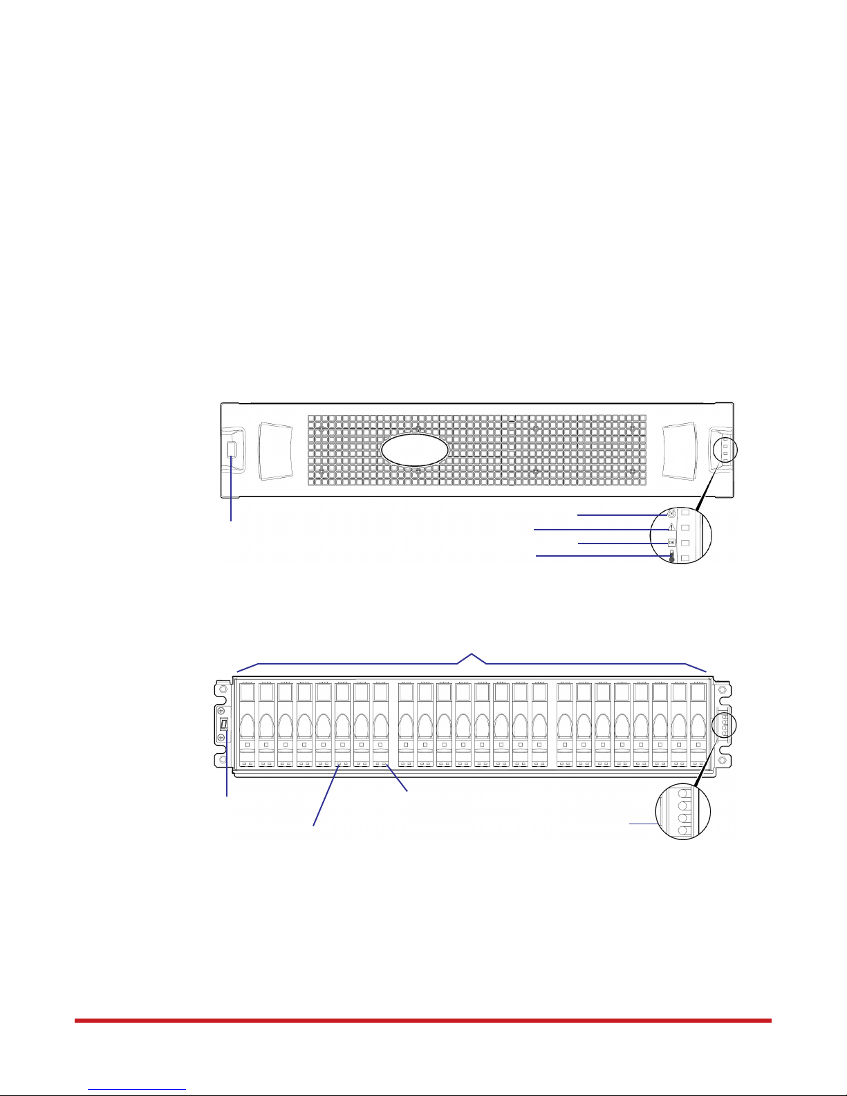
1.1 Front Panel Components
Figure 1 illustrates the front of an EF4024 enclosure with the bezel installed. The enclosure
status LEDs and enclosure ID LED are visible through the front bezel.
There are 24 disk bays at the front of the enclosure. Figure 2 illustrates the LEDs on the front
panel. Refer to Appendix A for LED descriptions.
Figure 1. Enclosure Front with Bezel Installed
System Components
Enclosure ID
Figure 2. LEDs on Front Panel
0 1 2 3 4 5 6 7 8 9 10 11 12 13 14 15 16 17
Enclosure ID
Disk Drive Status LED
(OK to Remove)
1.1.1 Disk Drives
Fault/Service Required
Temperature Fault
Disk Bays
Disk Drive Status LED
(Power/Activity/Fault)
Unit Locator
FRU OK
18 19
See Figure 1
20
21 22
23
EF4024 enclosures support SFF Midline SAS and SFF Enterprise SAS disks. For information
about creating vdisks and adding spares using different disk drive types, see the EF4024
RAIDar User Guide or online help.
96-30065-001 Rev. A0 DataDirect Networks EF4024 FC RAID System Setup Guide | 10
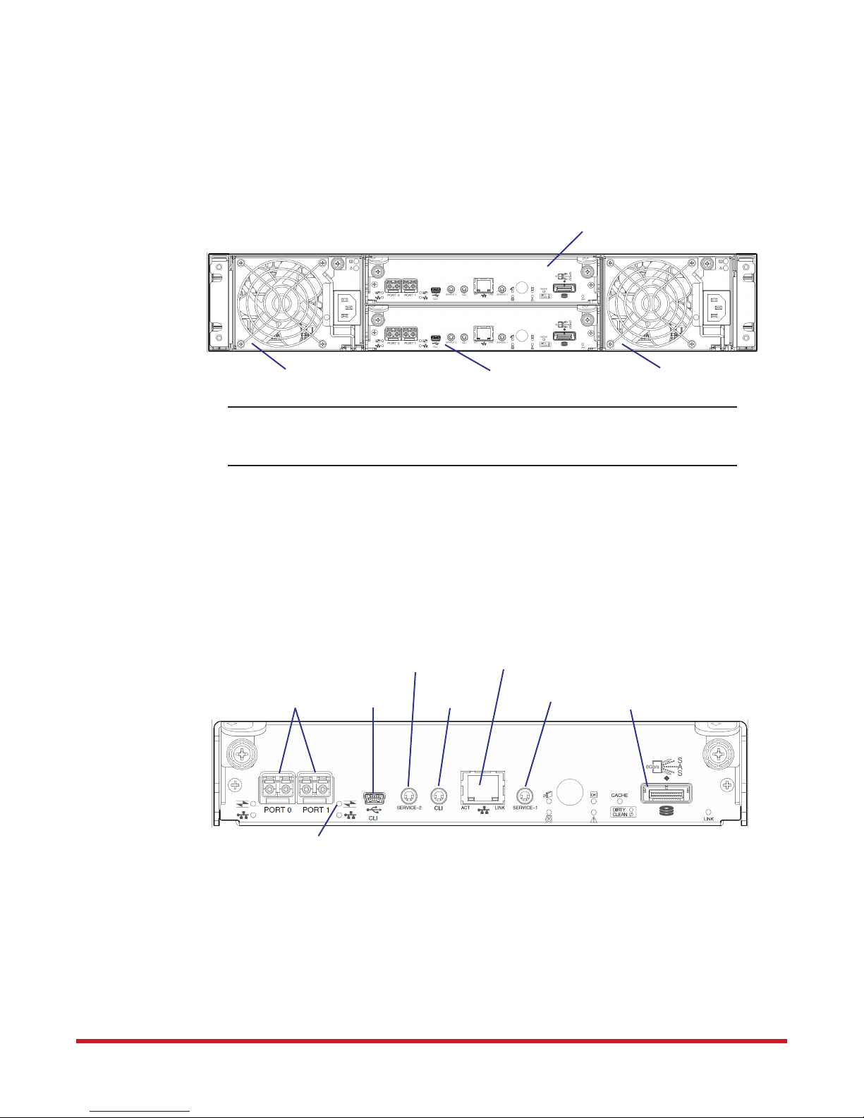
1.2 Controller Enclosure Rear Panel
Figure 3 shows the rear panel of the EF4024 controller enclosure. Each controller enclosure
includes two controller modules and two power and cooling modules. Refer to Appendix A
for LED descriptions.
System Components
Figure 3. Controller Enclosure Rear Panel
Power and Cooling Module
NOTE :
EF4024 enclosures support hot-plug replacement of redundant controller
modules, power and cooling modules, and expansion I/O modules. Hot-add
replacement of drive enclosures is also supported.
1.2.1 Controller Module
Figure 4 illustrates a controller module. The CNC ports are configured with SFPs supporting
either 8Gb or 16Gb FC connections.
Refer to the EF4024 RAIDar User Guide (Configuring Host Ports) for information on CNC
port configuration.
Controller Module B
Controller Module A
Power and Cooling Module
Figure 4. Controller Module
Service Port 2
CNC Ports for
Host Connections
CLI Port
FC LED
1.2.2 Power and Cooling Module
Power redundancy is achieved through two independent load-sharing power supplies. In the
event of a power supply failure, or the failure of the power source, the storage system can
operate continuously on a single power supply. Greater redundancy can be achieved by
connecting the power supplies to separate circuits.
Refer to Appendix A for LED descriptions on power and cooling modules.
(Not Used)
Network Port
Service Port 1
Mini-SAS Expansion Port
96-30065-001 Rev. A0 DataDirect Networks EF4024 FC RAID System Setup Guide | 11
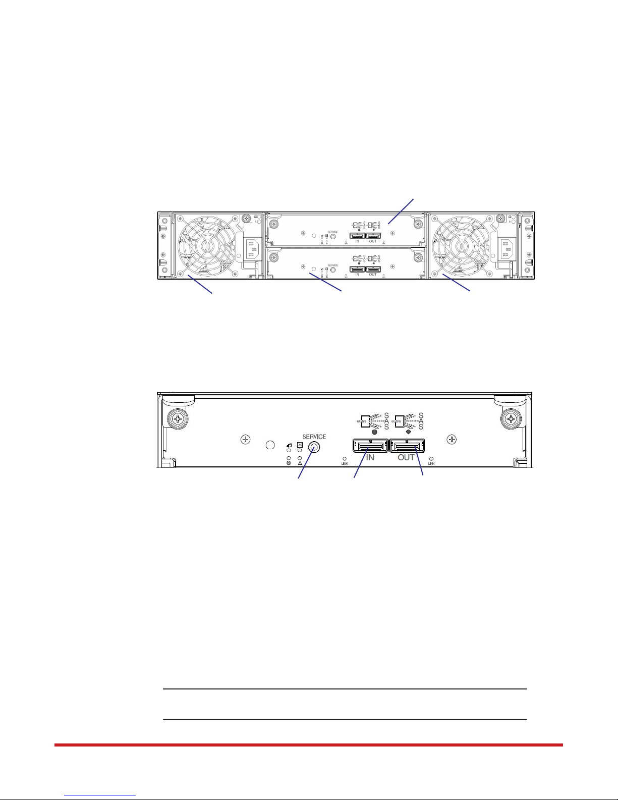
1.3 Expansion Enclosure Rear Panel
The EF4024 storage capacity can be increased by daisy-chaining expansion enclosures to the
controller enclosure. Up to three expansion enclosures are supported.
Figure 5 shows the rear panel of an EF4024 expansion enclosure. Each expansion enclosure
includes two expansion modules and two power and cooling modules. Refer to Appendix A
for LED descriptions.
Figure 5. Expansion Enclosure Rear Panel
System Components
Expansion Module A
Power and Cooling Module
1.3.1 Expansion Module
Figure 6 illustrates the I/O ports on an expansion module.
Figure 6. Expansion Module
1.4 Cache
To enable faster data access from disk storage, the following types of caching are performed:
• Write-back or write-through caching. The controller writes user data into the cache
memory in the controller module rather than directly to the disks. Later, when the
storage system is either idle or aging —and continuing to receive new I/O data—the
controller writes the data to the disks.
Service Port
Expansion Module B
SAS In Port
Power and Cooling Module
SAS Out Port
• Read-ahead caching. The controller detects sequential data access, reads ahead into the
next sequence of data—based upon settings—and stores the data in the read-ahead
cache. Then, if the next read access is for cached data, the controller immediately loads
the data into the system memory, avoiding the latency of a disk access.
TIP:
See “Volume cache options” and “System cache settings” in the EF4024 RAIDar
User Guide for setting options.
96-30065-001 Rev. A0 DataDirect Networks EF4024 FC RAID System Setup Guide | 12
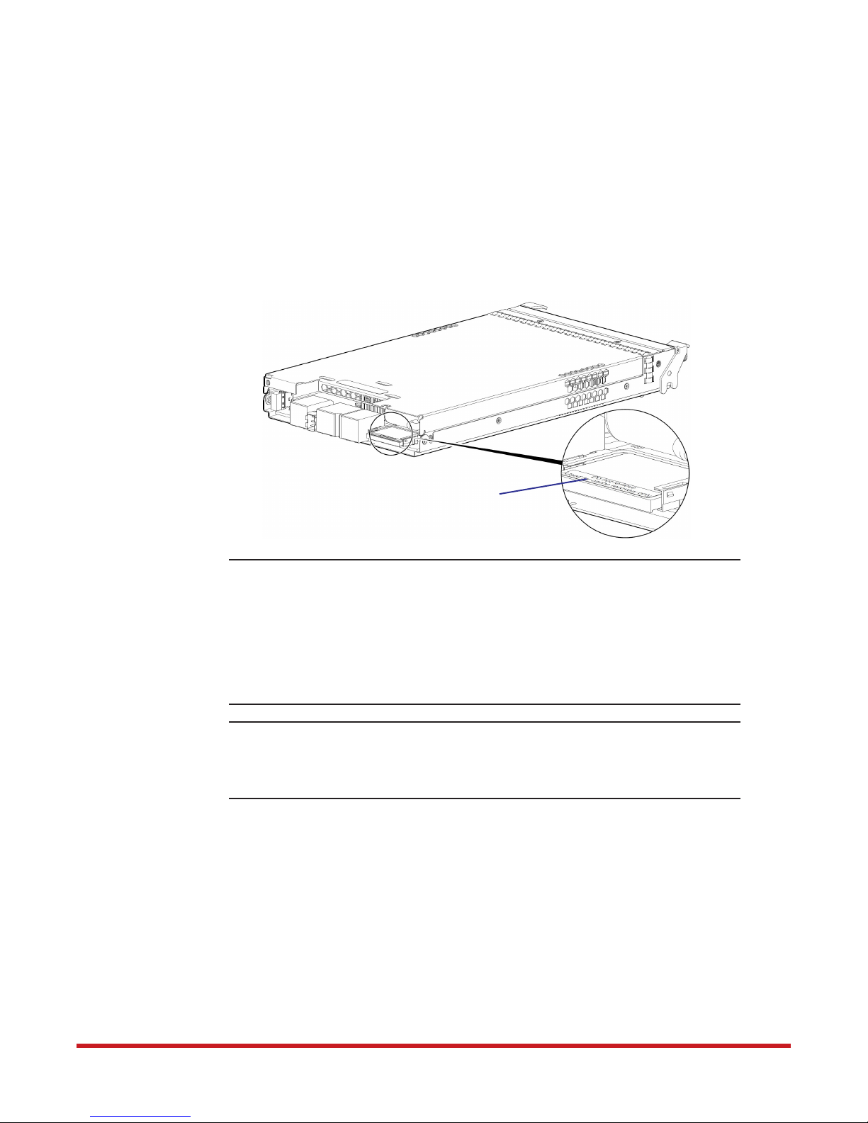
1.5 CompactFlash
During a power loss or controller failure, data stored in cache is saved off to non-volatile
memory (CompactFlash). The data is restored to cache, and then written to disk after the
issue is corrected. To protect against writing incomplete data to disk, the image stored on the
CompactFlash is verified before committing to disk.
The CompactFlash card is located at the midplane-facing end of the controller module as
shown in Figure 7. It is used for cache recovery only.
Figure 7. CompactFlash Card in Controller Module
System Components
CompactFlash Card
CAUTION :
IMPORTANT:
The CompactFlash card should only be removed for transportable
purposes. To preserve the existing data stored in the CompactFlash, you
must transport the CompactFlash from the failed controller to the
replacement controller. Failure to do so will result in the loss of data
stored in the cache module. The CompactFlash must stay with the same
enclosure. If the CompactFlash is used/installed in a different enclosure,
data loss/data corruption will occur. Contact DDN Support for guidance
on replacement procedure.
In dual-controller configurations featuring one healthy partner
controller, there is no need to transport failed controller cache to a
replacement controller because the cache is duplicated between the
controllers (subject to volume write optimization setting).
1.6 Supercapacitor Pack
To protect controller module cache in case of power failure, each controller enclosure
model is equipped with supercapacitor technology, in conjunction with CompactFlash
memory, built into each controller module to provide extended cache memory backup time.
The supercapacitor pack provides power for backing up unwritten data in the write cache
to the CompactFlash, in the event of a power failure. Unwritten data in CompactFlash
memory is automatically committed to disk media when power is restored. In the event of
power failure, while cache is maintained by the supercapacitor pack, the Cache Status LED
flashes at a rate of 1/10 second on and 9/10 second off.
96-30065-001 Rev. A0 DataDirect Networks EF4024 FC RAID System Setup Guide | 13

Chapter 2
2.0Installing Enclosures
96-30065-001 Rev. A0 DataDirect Networks EF4024 FC RAID System Setup Guide | 14
This chapter provides information on installing the EF4024 controller enclosure and
expansion enclosures.
2.1 Installation Checklist
Table 1 outlines the steps required to install the enclosures, and initially configure and
provision the storage system. To ensure successful installation, perform the tasks in the
order presented.
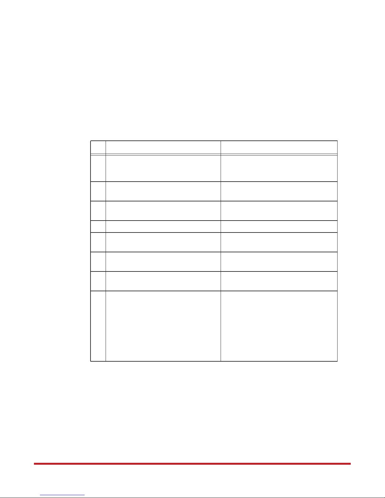
Table 1. Installation Checklist
Step Task Where to find procedure
Installing Enclosures
1. Install the controller enclosure and
optional expansion enclosures in the
rack
2. Connect controller enclosure and
Rackmount bracket kit installation
instructions pertaining to your
enclosure.
Section 2.2, Connecting the Enclosures
optional expansion enclosures
3. Connect power cords and power up the
system
Section 2.3, Powering On and Powering
Off
4. Install required host software Section 3.1, Host System Requirements
5. Connect hosts
1
Section 3.2, Connecting Enclosures to
Hosts
6. Connect remote management hosts
1
Section 3.3, Connecting a Management
Host on the Network
7. Obtain IP values and set network port IP
properties on the controller enclosure
8. Perform initial configuration tasks2:
a) Sign-in to the web-browser interface
(RAIDar) to access the application
GUI
b) Verify firmware revisions and update
if necessary
c) Initially configure and provision the
system using RAIDar
Section 3.5, Configuring Network
Interfaces
a) EF4024 RAIDar User Guide, Getting
Started
b) Section 3.4, Updating firmware. Also
see same topic in the EF4024
RAIDar User Guide
c) EF4024 RAIDar User Guide,
Configuring the System and
Provisioning the System
1. For more about hosts, refer to the EF4024 RAIDar User Guide (About hosts)
2. Also see Section 4.1
Additional installation notes:
• Controller modules within the same enclosure must be of the same type
• For optimal performance, do not mix 6 Gb and 3 Gb disk drives within the same
enclosure
96-30065-001 Rev. A0 DataDirect Networks EF4024 FC RAID System Setup Guide | 15

2.2 Connecting the Enclosures
The EF4024 controller enclosure supports up to three expansion enclosures, or a maximum
of 96 disk drives. The EF4024 enclosures support both straight-through and reverse SAS
cabling. Reverse cabling allows any drive enclosure to fail—or be removed—while
maintaining access to other enclosures. Fault tolerance and performance requirements
determine whether to optimize the configuration for high availability or high performance
when cabling. The EF4024 controller modules support both 3-Gbps and 6-Gbps internal disk
drive speeds together with 3-Gbps and 6-Gbps expander link speeds.
Installing Enclosures
CAUTION :
Cabling diagrams in this section show fault-tolerant cabling patterns. Controller and
expansion modules are identified by <enclosure-ID><controller-ID>. When connecting
multiple drive enclosures, use reverse cabling to ensure the highest level of fault tolerance,
enabling controllers to access remaining drive enclosures if a drive enclosure fails.
For example, Figure 10 shows reverse cabling, wherein controller 0A (with enclosure-ID=0;
controller-ID=A) is connected to expansion module 1A, with a chain of connections
cascading down (blue cable). Controller 0B is connected to the lower expansion module (B)
of the last drive enclosure in the chain, with connections moving in the opposite direction
(green cable).
Some 6-Gbps disks might not consistently support a 6-Gbps transfer
rate. If this happens, the system automatically adjusts transfers to those
disks to 3 Gbps, increasing reliability and reducing error messages with
little impact on system performance. This rate adjustment persists until
the controller is restarted or power-cycled.
2.2.1 Cable Requirements
The expansion enclosures, supporting 6 Gb internal disk drive and expander link speeds, can
be attached to an EF4024 controller enclosure using supported mini-SAS to mini-SAS cables.
The EF4024 enclosures support 6-Gbps or 3-Gbps expansion port data rates. Use only
DDN-qualified cables, and observe the following guidelines:
• When connecting SAS cables to expansion modules, use only supported mini-SAS x4
cables with SFF-8088 connectors supporting your 6 Gb application
• Qualified mini-SAS to mini-SAS cables are used to connect cascaded enclosures in the
rack; the “mini-SAS to mini-SAS” cable designator connotes SFF-8088 to SFF-8088
connectors
• The maximum expansion cable length allowed in any configuration is 2 meters (6.56')
• Cables required, if not included, must be separately purchased
• When adding more than two drive enclosures, you may need to purchase additional
1-meter or 2-meter cables, depending upon number of enclosures and cabling method
used; spanning 3 or 4 drive enclosures requires 1-meter (3.28') cables
• You may need to order additional or longer cables when reverse-cabling a fault-tolerant
configuration (see Figure 10).
• Use only DDN-qualified cables for host connections
96-30065-001 Rev. A0 DataDirect Networks EF4024 FC RAID System Setup Guide | 16
2.2.2 Enclosure Cabling Diagrams
The cabling diagrams in this section show both the reverse and straight-through cabling
schemes for the EF4024 controller enclosures and expansion enclosures.
For clarity, the cabling diagrams show only relevant details such as faceplate outlines and
expansion ports. For detailed enclosure illustrations, refer to Chapter 1.
Figure 8 shows how to connect one expansion enclosure to the controller enclosure.
Figure 8. Connecting One Expansion Enclosure to Controller Enclosure
Controller Module 0A
Controller Module 0B
Expansion
Module 1A
Expansion
Module 1B
Installing Enclosures
Controller
Enclosure 0
Out
In
In
Out
Expansion
Enclosure 1
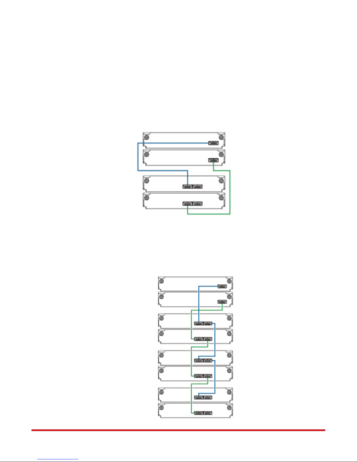
Figure 9 shows the straight-through cabling scheme. Using this method, if an expansion
enclosure fails, the enclosures that follow the failed enclosure in the chain are no longer
accessible until the failed enclosure is repaired or replaced.
Figure 9. Connecting Three Expansion Enclosures (Straight-Through Cabling)
Controller
Controller
Enclosure 0
Expansion
Enclosure 1
Expansion
Enclosure 2
Expansion
Enclosure 3
Module 0A
Controller
Module 0B
Expansion
Module 1A
Expansion
Module 1B
Expansion
Module 2A
Expansion
Module 2B
Expansion
Module 3A
Expansion
Module 3B
In
Out
In
Out
In
Out
Out
In
In
Out
In
Out
96-30065-001 Rev. A0 DataDirect Networks EF4024 FC RAID System Setup Guide | 17
Installing Enclosures
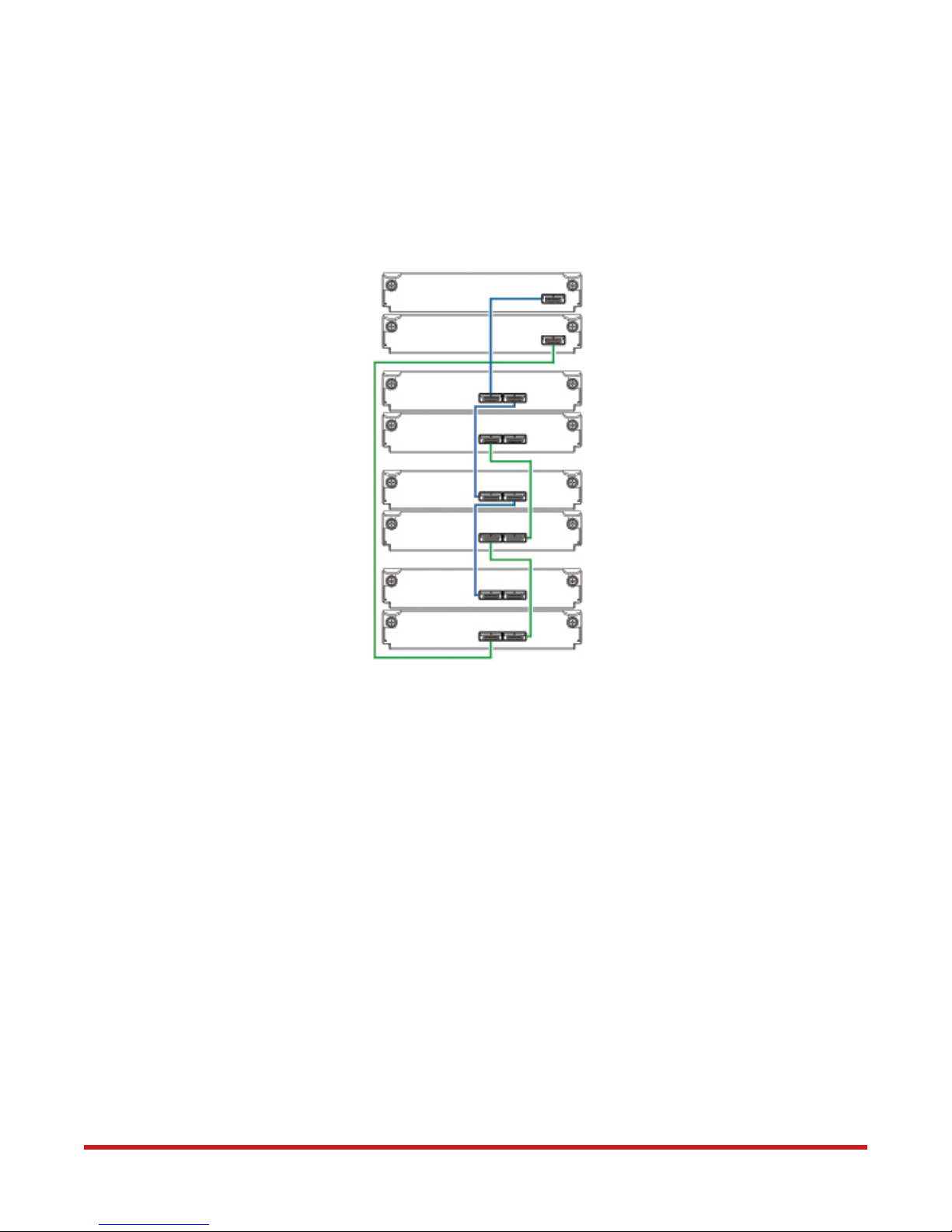
Figure 10 shows the reverse cabling scheme. Controller module 0A is connected to
expansion module 1A, with a chain of connections cascading down (blue). Controller
module 0B is connected to the lower expansion module (3B), of the last expansion
enclosure, with connections moving in the opposite direction (green). Reverse cabling
allows any expansion enclosure to fail—or be removed—while maintaining access to other
enclosures.
Figure 10. Connecting Three Expansion Enclosures (Reverse Cabling)
Controller
Module 0A
Controller
Module 0B
Controller
Enclosure 0
Expansion
Module 1A
Expansion
Module 1B
Expansion
Module 2A
Expansion
Module 2B
Expansion
Module 3A
Expansion
Module 3B
Out
In
In
Out
In
Out
In
Out
Out
In
In
Out
2.3 Powering On and Powering Off
Note the following before powering on the enclosures for the first time:
• Install all disk drives in the enclosure so the controller can identify and configure them
at power-up
Expansion
Enclosure 1
Expansion
Enclosure 2
Expansion
Enclosure 3
• Connect the power cords to the enclosures (as described in Section 2.3.1)
• Generally, when powering up, make sure to power up the enclosures and associated
data host in the following order:
❖ Expansion enclosures first
This ensures that the disks in the expansion enclosures have enough time to
completely spin up before being scanned by the controller modules within the
controller enclosure.
While enclosures power up, their LEDs blink. After the LEDs stop blinking—if no
LEDs on the front and back of the enclosure are amber—the power-on sequence is
complete, and no faults have been detected. See Appendix A for LED descriptions.
96-30065-001 Rev. A0 DataDirect Networks EF4024 FC RAID System Setup Guide | 18
❖ Controller enclosure next
Depending upon the number and type of disks in the system, it may take several
minutes for the system to become ready.
❖ Data host last (if powered down for maintenance purposes)
TIP:
In general, when powering off, you will reverse the order of steps used for
powering on.
2.3.1 Powering on the System
To power on the system:
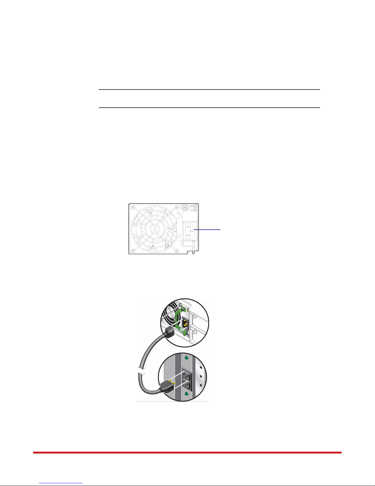
1. Connect one end of the power cords to the power cord connectors on the back of all
expansion enclosures (Figure 11). Only the power cords supplied with the enclosures
should be used.
Figure 11. Power Cord Connector on Power Supply Modules
Installing Enclosures
Power Cord Connector
2. Connect the other end of the power cords to the rack power source (Figure 12). For
redundancy, connect the two power supplies to separate power source.
Figure 12. Connect Power Cords to Rack Power Source
3. Allow a couple of minutes for the disks to spin up.
4. Similarly, connect the power cords between the controller enclosure’s power supplies
and the rack power source. Only the power cords supplied with the enclosures should
be used.
96-30065-001 Rev. A0 DataDirect Networks EF4024 FC RAID System Setup Guide | 19

2.3.2 Powering off the System
1. Stop all I/O from hosts to the system (see Section 5.3, Stopping I/O on page 35).
2. Shut down both controllers using one of the two methods below:
❖ Use RAIDar to shut down both controllers, as described in the EF4024 RAIDar
User Guide
❖ Use the command-line user interface (CLUI) to shut down both controllers, as
described in the EF4024 CLUI Command Reference Guide
3. Turn off the controller enclosure by unplugging the power cords from the rack power
source.
4. Turn off all expansion enclosures by unplugging the power cords from the rack power
source.
Installing Enclosures
96-30065-001 Rev. A0 DataDirect Networks EF4024 FC RAID System Setup Guide | 20

Chapter 3
3.0Connecting Hosts
96-30065-001 Rev. A0 DataDirect Networks EF4024 FC RAID System Setup Guide | 21

This chapter provides information on how to connect your hosts to the EF4024 FC RAID
system.
3.1 Host System Requirements
Hosts connected to an EF4024 controller enclosure must meet the following requirements:
• Depending on your system configuration, host operating systems may require that
multipathing is supported.
• If fault tolerance is required, then multipathing software may be required. Host-based
multipath software should be used in any configuration where two logical paths
between the host and any storage volume may exist at the same time. This would
include most configurations where there are multiple connections to the host or
multiple connections between a switch and the storage.
Use native Microsoft MPIO DSM support with Windows Server 2008 and Windows
Server 2013. Use either the Server Manager or the command-line interface (mpclaim
CLI tool) to perform the installation.
See the following web sites for information on using native Microsoft MPIO DSM:
http://support.microsoft.com/gp/assistsupport
http://technet.microsoft.com (search for “multipath I/O overview”)
Connecting Hosts
3.1.1 Cabling Considerations
Common cabling configurations address hosts, controller enclosures, drive enclosures, and
switches. Host interface ports on EF4024 controller enclosures can connect to respective
hosts via direct-attach or switch-attach.
Qualified options support cable lengths of 1 m (3.28'), 2 m (6.56'), 5 m (16.40'), 15 m (49.21'),
30 m (98.43'), and 50 m (164.04') for OM4 multimode optical cables and OM3 multimode FC
cables, respectively. A 0.5 m (1.64') cable length is also supported for OM3.
3.2 Connecting Enclosures to Hosts
A host identifies an external port to which the storage system is attached. Cable connections
vary depending on configuration. This section shows a few common cabling configurations.
NOTE :
ULP can show all LUNs through all host ports on both controllers, and the interconnect
information is managed by the controller firmware. ULP appears to the host as an
active-active storage system, allowing the host to select any available path to access the
LUN, regardless of vdisk ownership.
EF4024 controllers use Unified LUN Presentation (ULP)—a controller feature
enabling a host to access mapped volumes through any controller host
port.
96-30065-001 Rev. A0 DataDirect Networks EF4024 FC RAID System Setup Guide | 22
 Loading...