

DataDirect Networks EF3015 Setup Manual

EF3015
Fibre Channel Controller Enclosure
Setup Guide
Rev A

Important Information
Information in this document is subject to change without notice and does not represent a commitment on
the part of DataDirect Networks, Inc. No part of this manual may be reproduced or transmitted in any form
or by any means, electronic or mechanical, including photocopying and recording, for any purpose other
than the purchaser’s personal use without the written permission of DataDirect Networks, Inc.
© 2010 DataDirect Networks, Inc. All rights reserved.
DataDirect Networks, the DataDirect Networks logo, Silicon Storage Architecture, S2A, Web Object Scaler,
and Storage Fusion Architecture are trademarks of DataDirect Networks, Inc. All other brand and product
names are trademarks of their respective holders.
DataDirect Networks’ Licensor(s) makes no warranties, express or implied, including without limitation the
implied warranties of merchantability and fitness for a particular purpose, regarding the software.
DataDirect Networks’ Licensor(s) does not warrant, guarantee or make any representations regarding the
use or the results of the use of the software in terms of its correctness, accuracy, reliability, currentness, or
otherwise. The entire risk as to the results and performance of the software is assumed by you. The exclusion
of implied warranties is not permitted by some jurisdictions. The above exclusion may not apply to you.
In no event will DataDirect Networks’ Licensor(s), and their directors, officers, employees, or agents
(collectively DataDirect Networks’ Licensors) be liable to you for any consequential, incidental, or indirect
damages (including damages for loss of business profits, business interruption, loss of business information,
and the like) arising out of the use or inability to use the software even if DataDirect Networks’ Licensor has
been advised of the possibility of such damages. Because some jurisdictions do not allow the exclusion or
limitation of liability for consequential or incidental damages, the above limitations may not apply to you.
DataDirect Networks’ Licensor’s liability to you for actual damages from any cause whatsoever, and
regardless of the form of the action (whether in contract, tort (including negligence), product liability or
otherwise), will be limited to $50.
Document Number 96-00274-001 Rev A
Nov 2010
EF3015 Setup Guide (Rev A)
2

Important Information
STANDARD WARRANTY
Definitions: This two-year limited warranty applies to the following DataDirect Networks network infrastructure and
individual SAN solution components that include: Silicon Storage Appliance Hardware, Disk Modules, RAID Hardware
Components, Storage Hardware Components, and Disk Docking Bays and Enclosures (hereinafter “DataDirect
Networks Products”). Fibre Channel Interface Kits, SCSI Interface Kits, Host Adapters and Networking Products are
limited to a 90-day warranty. Software bundled or included with DataDirect Networks solutions are furnished exclusively
under the terms of the applicable license agreements.
Warranty: DataDirect Networks warrants that the DataDirect Networks Products accompanied by this limited Warranty
are free from defects in material and workmanship for a period of two years from the date of original purchase from
DataDirect Networks or an authorized DataDirect Networks reseller. During the term of this Warranty, DataDirect
Networks will, at its option, repair or replace any defective parts of the DataDirect Networks products purchased under
this Warranty at no additional charge. Repair parts or replacement DataDirect Networks products will be furnished on
an exchange basis, and will be either reconditioned or new. When returning the DataDirect Networks products, the
Purchaser must prepay any shipping charges. In addition, the Purchaser is responsible for insuring the products returned
and assumes the risk of loss during shipment.
Warranty Claim Requirements: Purchaser claims made pursuant to this Warranty must conform to the following
requirements:
1. The DataDirect Networks products must be returned to (a) an Authorized DataDirect Networks Servicing Reseller in
the country of original purchase, or (b) a DataDirect Networks facility which performs Warranty service in the country
of original purchase, or (c) an Authorized DataDirect Networks Third Party Service Provider in the country of original
purchase.
2. The Purchaser must provide proof of purchase and date of purchase from DataDirect Networks or an Authorized
DataDirect Networks Reseller.
3. The Purchaser may request information on how to obtain warranty service by contacting any Authorized DataDirect
Networks Reseller, or by writing to the Warranty Service Department, DataDirect Networks, 9351 Deering Avenue,
Chatsworth, CA 91311.
Disclaimers: THIS LIMITED WARRANTY DOES NOT APPLY TO ANY DATADIRECT NETWORKS PRODUCTS WHICH
HAVE BEEN DAMAGED OR RENDERED DEFECTIVE (a) AS A RESULT OF ACCIDENT, MISUSE, OR ABUSE; (b) BY
THE USE OF PARTS NOT MANUFACTURED OR SOLD BY DATADIRECT NETWORKS; (c) BY MODIFICATION
WITHOUT THE WRITTEN PERMISSION OF DATADIRECT NETWORKS, OR (d) AS A RESULT OF SERVICE BY
ANYONE OTHER THAN DATADIRECT NETWORKS, AN AUTHORIZED DATADIRECT NETWORKS SERVICING
RESELLER, OR AN AUTHORIZED DATADIRECT NETWORKS THIRD PARTY SERVICE PROVIDER.
EXCEPT AS EXPRESSLY SET FORTH ABOVE, DATADIRECT NETWORKS MAKES NO OTHER WARRANTIES,
EXPRESS OR IMPLIED, INCLUDING, BUT NOT LIMITED TO, ANY IMPLIED WARRANTIES OF MERCHANTABILITY
AND FITNESS FOR PURPOSE, AND DATADIRECT NETWORKS EXPRESSLY DISCLAIMS ALL WARRANTIES NOT
STATED HEREIN. IN THE EVENT THE PRODUCTS ARE NOT FREE FROM DEFECTS AS WARRANTED ABOVE, THE
PURCHASER'S SOLE REMEDY SHALL BE REPAIR OR REPLACEMENT AS PROVIDED ABOVE. UNDER NO
CIRCUMSTANCES WILL DATADIRECT NETWORKS BE LIABLE TO THE PURCHASER, OR TO ANY USER, FOR ANY
DAMAGES, EXPENSES, LOST PROFITS, LOST SAVINGS, DAMAGE TO OR REPLACEMENT OF EQUIPMENT AND
PROPERTY, COSTS OF RECOVERING, REPROGRAMMING, OR REPRODUCING ANY PROGRAM OR DATA STORED
IN OR USED WITH THE PRODUCTS, OR OTHER DAMAGES ARISING OUT OF THE USE OR INABILITY TO USE THE
DATADIRECT NETWORKS PRODUCTS.
ANY IMPLIED WARRANTIES ARE LIMITED TO THE TERMS OF THIS EXPRESS LIMITED WARRANTY. SOME
STATES DO NOT ALLOW THE EXCLUSION OR LIMITATION OF INCIDENTAL OR CONSEQUENTIAL DAMAGES FOR
CONSUMER PRODUCTS, AND SOME STATES DO NOT ALLOW LIMITATIONS ON HOW LONG AN IMPLIED
WARRANTY LASTS, SO THE ABOVE LIMITATIONS OR EXCLUSIONS MAY NOT APPLY TO YOU. THIS WARRANTY
GIVES YOU SPECIFIC LEGAL RIGHTS, AND YOU MAY ALSO HAVE OTHER RIGHTS WHICH VARY FROM STATE TO
STATE.
EF3015 Setup Guide (Rev A)
3

Preface
This guide provides information about the EF3015 Fibre Channel Controller Enclosure:
The EF3015 isMIL-STD-compliant and supports large form factor (LFF 12-disk) drive
enclosures — using either AC or DC power supplies.
NOTE :
components.
See "The EF3015 System Components" for details regarding enclosure
Intended audience
This guide is intended for use by system administrators and technicians who are
experienced with the following:
• Direct attach storage (DAS) or storage area network (SAN) management
• Network administration
• Network installation
• Storage system installation and configuration
Prerequisites
Prerequisites for installing and configuring this product include familiarity with:
• Servers and computer networks
• Fibre Channel (FC), Serial Attached SCSI (SAS), Internet SCSI (iSCSI), and Ethernet
protocols
Related Documentation
• EF3015 Command Line User Interface (CLUI) Command Reference
• EF3015 Quick Start Guide
• EF3015 Rackmount Bracket Kit Installation Instructions
• EF3015 RAIDar User Guide
EF3015 Setup Guide (Rev A)
4
Document Conventions and Symbols
Warning
!
Convention Element
Blue text Cross-reference links
Bold font • Key names
• Text typed into a GUI element, such as into a
box
• GUI elements that are clicked or selected, such
as menu and list items, buttons, and check
boxes
Italics font Text emphasis
Monospace font • File and directory names
• System output
•Code
• Text typed at the command-line
Preface
Monospace, italic font • Code variables
• Command-line variables
Monospace, bold font Emphasis of file and directory names, system
output, code, and text typed at the command line
indicates that failure to follow directions could result in bodily harm or
death.
NOTE :
Caution ! indicates that failure to follow directions could result in damage to the
equipement or data.
IMPORTANT :
provides additional information.
provides clarifying information or specific instructions.
TIP :
EF3015 Setup Guide (Rev A)
provides helpful hints and shortcuts.
5

Table of Contents
Table of Contents
Preface
Intended audience
Prerequisites. . . . . . . . . . . . . . . . . . . . . . . . . . . . . . . . . . . . . . . . . . . . . . . . . . . . . . . . . . . . . . . . . . . . . . . . . . . . 4
Related Documentation . . . . . . . . . . . . . . . . . . . . . . . . . . . . . . . . . . . . . . . . . . . . . . . . . . . . . . . . . . . . . . . . . 4
Document Conventions and Symbols . . . . . . . . . . . . . . . . . . . . . . . . . . . . . . . . . . . . . . . . . . . . . . . . . . . . 5
1 The EF3015 System Components . . . . . . . . . . . . . . . . . . . . . . . . . . . . . . . . . . . . . . . . . . . . . . . . . . . 8
1.1 Front Panel Components. . . . . . . . . . . . . . . . . . . . . . . . . . . . . . . . . . . . . . . . . . . . . . . . . 8
1.2 Disk Drive Slot Numbers. . . . . . . . . . . . . . . . . . . . . . . . . . . . . . . . . . . . . . . . . . . . . . . . . 8
1.3 EF3015 Controller Enclosure Rear Panel Components . . . . . . . . . . . . . . . . . . . . . . . 9
1.3.1 Controller Module Face Plate . . . . . . . . . . . . . . . . . . . . . . . . . . . . . . . . . . . . . . . . . . . . . . . . 9
1.4 Cache . . . . . . . . . . . . . . . . . . . . . . . . . . . . . . . . . . . . . . . . . . . . . . . . . . . . . . . . . . . . . . . . . 9
1.5 CompactFlash . . . . . . . . . . . . . . . . . . . . . . . . . . . . . . . . . . . . . . . . . . . . . . . . . . . . . . . . . 10
1.6 Super-Capacitor Pack . . . . . . . . . . . . . . . . . . . . . . . . . . . . . . . . . . . . . . . . . . . . . . . . . . 10
2 Installation. . . . . . . . . . . . . . . . . . . . . . . . . . . . . . . . . . . . . . . . . . . . . . . . . . . . . . . . . . . . . . . . . . . . . . . . 11
2.1 Installation Checklist . . . . . . . . . . . . . . . . . . . . . . . . . . . . . . . . . . . . . . . . . . . . . . . . . . . 11
2.2 Powering on/Powering Off . . . . . . . . . . . . . . . . . . . . . . . . . . . . . . . . . . . . . . . . . . . . . . 12
2.3 AC PSU . . . . . . . . . . . . . . . . . . . . . . . . . . . . . . . . . . . . . . . . . . . . . . . . . . . . . . . . . . . . . . 13
2.4 DC and AC PSUs with power switch . . . . . . . . . . . . . . . . . . . . . . . . . . . . . . . . . . . . . . 14
2.4.1 Power Cords . . . . . . . . . . . . . . . . . . . . . . . . . . . . . . . . . . . . . . . . . . . . . . . . . . . . . . . . . . . . . . . 14
. . . . . . . . . . . . . . . . . . . . . . . . . . . . . . . . . . . . . . . . . . . . . . . . . . . . . . . . . . . . . . . . . . . . . . 4
3 Connecting Hosts . . . . . . . . . . . . . . . . . . . . . . . . . . . . . . . . . . . . . . . . . . . . . . . . . . . . . . . . . . . . . . . . . 17
3.1 Host System Requirements . . . . . . . . . . . . . . . . . . . . . . . . . . . . . . . . . . . . . . . . . . . . . . 17
3.2 Cabling Considerations . . . . . . . . . . . . . . . . . . . . . . . . . . . . . . . . . . . . . . . . . . . . . . . . . 17
3.3 Connecting the Enclosure to Hosts . . . . . . . . . . . . . . . . . . . . . . . . . . . . . . . . . . . . . . . 17
3.3.1 FC Host Ports . . . . . . . . . . . . . . . . . . . . . . . . . . . . . . . . . . . . . . . . . . . . . . . . . . . . . . . . . . . . . . 18
3.4 Connecting Direct Attach Configurations. . . . . . . . . . . . . . . . . . . . . . . . . . . . . . . . . . 18
3.4.1 Single-Controller Configurations . . . . . . . . . . . . . . . . . . . . . . . . . . . . . . . . . . . . . . . . . . . . 19
3.4.2 Dual-Controller Configurations . . . . . . . . . . . . . . . . . . . . . . . . . . . . . . . . . . . . . . . . . . . . . 19
3.5 Connecting Switch Attach Configurations . . . . . . . . . . . . . . . . . . . . . . . . . . . . . . . . . 20
3.6 Connecting a Management Host on the Network . . . . . . . . . . . . . . . . . . . . . . . . . . . 20
3.7 Connecting Two Storage Systems to Replicate Volumes . . . . . . . . . . . . . . . . . . . . . 20
3.7.1 Dual-Controller Configuration . . . . . . . . . . . . . . . . . . . . . . . . . . . . . . . . . . . . . . . . . . . . . . 21
3.8 Updating Firmware . . . . . . . . . . . . . . . . . . . . . . . . . . . . . . . . . . . . . . . . . . . . . . . . . . . . 22
3.9 Obtaining IP Values . . . . . . . . . . . . . . . . . . . . . . . . . . . . . . . . . . . . . . . . . . . . . . . . . . . . 22
3.9.1 Setting Network Port IP Addresses using DHCP . . . . . . . . . . . . . . . . . . . . . . . . . . . . . 22
3.9.2 Setting Network Port IP Addresses using the CLI . . . . . . . . . . . . . . . . . . . . . . . . . . . . 23
4 Basic Operation . . . . . . . . . . . . . . . . . . . . . . . . . . . . . . . . . . . . . . . . . . . . . . . . . . . . . . . . . . . . . . . . . . . 27
4.1 Accessing RAIDar. . . . . . . . . . . . . . . . . . . . . . . . . . . . . . . . . . . . . . . . . . . . . . . . . . . . . . 27
4.2 Configuring and provisioning the storage system . . . . . . . . . . . . . . . . . . . . . . . . . . . 27
5 Troubleshooting . . . . . . . . . . . . . . . . . . . . . . . . . . . . . . . . . . . . . . . . . . . . . . . . . . . . . . . . . . . . . . . . . . 28
5.1 USB CLI port connection . . . . . . . . . . . . . . . . . . . . . . . . . . . . . . . . . . . . . . . . . . . . . . . 28
5.2 Fault isolation methodology . . . . . . . . . . . . . . . . . . . . . . . . . . . . . . . . . . . . . . . . . . . . . 28
5.2.1 Gather fault information . . . . . . . . . . . . . . . . . . . . . . . . . . . . . . . . . . . . . . . . . . . . . . . . . . . . 28
5.2.2 Determine where the fault is occurring. . . . . . . . . . . . . . . . . . . . . . . . . . . . . . . . . . . . . . 29
5.2.3 Review the event logs . . . . . . . . . . . . . . . . . . . . . . . . . . . . . . . . . . . . . . . . . . . . . . . . . . . . . . 29
5.2.4 Isolate the fault . . . . . . . . . . . . . . . . . . . . . . . . . . . . . . . . . . . . . . . . . . . . . . . . . . . . . . . . . . . . 29
5.2.5 If the enclosure does not initialize . . . . . . . . . . . . . . . . . . . . . . . . . . . . . . . . . . . . . . . . . . 29
5.2.6 Correcting enclosure IDs . . . . . . . . . . . . . . . . . . . . . . . . . . . . . . . . . . . . . . . . . . . . . . . . . . . 29
EF3015 Setup Guide (Rev A)
6

Table of Contents
5.3 Diagnostic steps . . . . . . . . . . . . . . . . . . . . . . . . . . . . . . . . . . . . . . . . . . . . . . . . . . . . . . . 30
5.4 Controller failure in a single-controller configuration . . . . . . . . . . . . . . . . . . . . . . . 34
5.5 Isolating a host-side connection fault . . . . . . . . . . . . . . . . . . . . . . . . . . . . . . . . . . . . . 35
5.6 Isolating a controller module expansion port connection fault. . . . . . . . . . . . . . . . 37
5.7 Isolating AssuredRemote replication faults . . . . . . . . . . . . . . . . . . . . . . . . . . . . . . . . 38
5.8 Diagnostic steps for replication setup. . . . . . . . . . . . . . . . . . . . . . . . . . . . . . . . . . . . . 39
5.9 Resolving voltage and temperature warnings. . . . . . . . . . . . . . . . . . . . . . . . . . . . . . . 42
Appendix A. LED Descriptions . . . . . . . . . . . . . . . . . . . . . . . . . . . . . . . . . . . . . . . . . . . . . . . . . . . . . . . . . . 44
A.1 12-Drive Enclosure Front Panel LEDs. . . . . . . . . . . . . . . . . . . . . . . . . . . . . . . . . . . . . 44
A.2 Disk Drive LEDs . . . . . . . . . . . . . . . . . . . . . . . . . . . . . . . . . . . . . . . . . . . . . . . . . . . . . . . 45
A.3 EF3015 Rear Panel LEDs. . . . . . . . . . . . . . . . . . . . . . . . . . . . . . . . . . . . . . . . . . . . . . . . 46
A.4 Power supply LEDs . . . . . . . . . . . . . . . . . . . . . . . . . . . . . . . . . . . . . . . . . . . . . . . . . . . . 47
Appendix B. Environmental Requirements & Specifications . . . . . . . . . . . . . . . . . . . . . . . . . . . . . 48
B.1 Safety Requirements . . . . . . . . . . . . . . . . . . . . . . . . . . . . . . . . . . . . . . . . . . . . . . . . . . . 48
B.2 Site Requirements and Guidelines . . . . . . . . . . . . . . . . . . . . . . . . . . . . . . . . . . . . . . . . 48
B.2.1 Site Wiring and AC Power Requirements . . . . . . . . . . . . . . . . . . . . . . . . . . . . . . . . . . . . 48
B.2.2 Site Wiring and DC Power Requirements . . . . . . . . . . . . . . . . . . . . . . . . . . . . . . . . . . . . 49
B.2.3 Weight and Placement Guidelines. . . . . . . . . . . . . . . . . . . . . . . . . . . . . . . . . . . . . . . . . . . 49
B.2.4 Electrical guidelines. . . . . . . . . . . . . . . . . . . . . . . . . . . . . . . . . . . . . . . . . . . . . . . . . . . . . . . . 50
B.2.5 Ventilation requirements . . . . . . . . . . . . . . . . . . . . . . . . . . . . . . . . . . . . . . . . . . . . . . . . . . . 50
B.2.6 Cabling requirements. . . . . . . . . . . . . . . . . . . . . . . . . . . . . . . . . . . . . . . . . . . . . . . . . . . . . . . 50
B.3 Management Host Requirements . . . . . . . . . . . . . . . . . . . . . . . . . . . . . . . . . . . . . . . . . 51
B.4 Physical Requirements . . . . . . . . . . . . . . . . . . . . . . . . . . . . . . . . . . . . . . . . . . . . . . . . . 51
B.5 Environmental Requirements . . . . . . . . . . . . . . . . . . . . . . . . . . . . . . . . . . . . . . . . . . . . 52
B.6 Electrical Requirements . . . . . . . . . . . . . . . . . . . . . . . . . . . . . . . . . . . . . . . . . . . . . . . . 52
B.6.1 Site Wiring and Power Requirements. . . . . . . . . . . . . . . . . . . . . . . . . . . . . . . . . . . . . . . . 52
B.6.2 Power Cord Requirements. . . . . . . . . . . . . . . . . . . . . . . . . . . . . . . . . . . . . . . . . . . . . . . . . . 52
Appendix C. Electrostatic Discharge . . . . . . . . . . . . . . . . . . . . . . . . . . . . . . . . . . . . . . . . . . . . . . . . . . . . 53
C.1 Preventing Electrostatic Discharge . . . . . . . . . . . . . . . . . . . . . . . . . . . . . . . . . . . . . . . 53
C.2 Grounding Methods to Prevent Electrostatic Discharge . . . . . . . . . . . . . . . . . . . . . 53
Appendix D. USB Device Connection . . . . . . . . . . . . . . . . . . . . . . . . . . . . . . . . . . . . . . . . . . . . . . . . . . . 54
D.1 Rear Panel USB Ports . . . . . . . . . . . . . . . . . . . . . . . . . . . . . . . . . . . . . . . . . . . . . . . . . . 54
D.1.1 USB CLI Port. . . . . . . . . . . . . . . . . . . . . . . . . . . . . . . . . . . . . . . . . . . . . . . . . . . . . . . . . . . . . . . 54
D.1.2 Emulated Serial Port . . . . . . . . . . . . . . . . . . . . . . . . . . . . . . . . . . . . . . . . . . . . . . . . . . . . . . . 55
D.1.3 Supported Host Applications . . . . . . . . . . . . . . . . . . . . . . . . . . . . . . . . . . . . . . . . . . . . . . . 55
D.1.4 Command Line Interface . . . . . . . . . . . . . . . . . . . . . . . . . . . . . . . . . . . . . . . . . . . . . . . . . . . 55
D.2 Device Driver/Special Operation Mode. . . . . . . . . . . . . . . . . . . . . . . . . . . . . . . . . . . . 55
D.2.1 Microsoft Windows. . . . . . . . . . . . . . . . . . . . . . . . . . . . . . . . . . . . . . . . . . . . . . . . . . . . . . . . . 56
D.2.2 Linux . . . . . . . . . . . . . . . . . . . . . . . . . . . . . . . . . . . . . . . . . . . . . . . . . . . . . . . . . . . . . . . . . . . . . . 56
Index . . . . . . . . . . . . . . . . . . . . . . . . . . . . . . . . . . . . . . . . . . . . . . . . . . . . . . . . . . . . . . . . . . . . . . . . . . . . . . . . . . 57
EF3015 Setup Guide (Rev A)
7
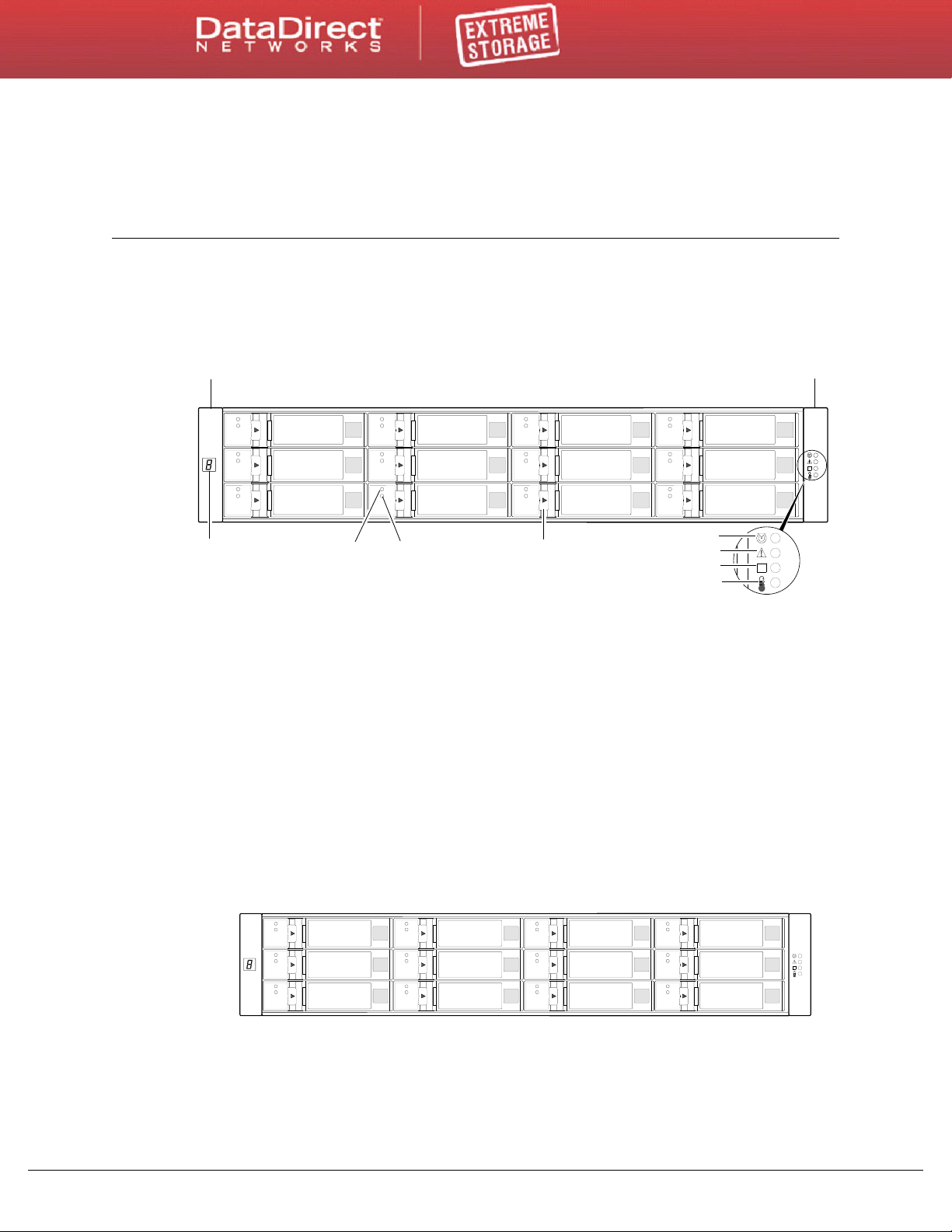
1.1 Front Panel Components
OKOK
OK
21
5
34
6
7
8
Left Ear
Right Ear
1 - Enclosure ID LED
2 - Disk drive status LED: OK to Remove
3 - Disk drive status LED: Power/Activity/Fault
4 - 3.5” disk or drive blank (typical 12 slots)
5 - Enclosure status LED: Unit Locator
6 - Enclosure status LED: Fault/Service Required
7 - Enclosure status LED: FRU OK
8 - Enclosure status LED: Temperature Fault
OK
0
1
2
3
4
5
6
7
8
9
10
11
1
The EF3015 System Components
1.2 Disk Drive Slot Numbers
EF3015 Setup Guide (Rev A)
8
The EF3015 System Components
SERVICE
1
0
CACHE
CLI CLI HOST
8G
2,4G
8G
2,4G
SERVICE
1
0
CACHE
CLI CLI HOST
8G
2,4G
8G
2,4G
6Gb/s
6Gb/s
132467 9
11
10
12
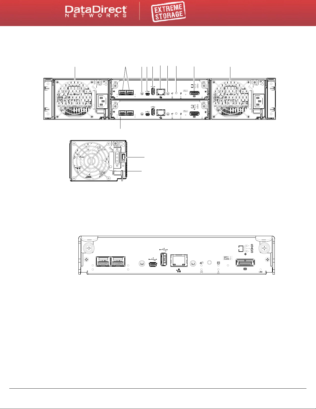
(DC power supply unit (PSU) is
5 8 1
mutually exclusive to the AC model)
1 - AC power supplies
2 - Host interface ports (FC)
3 - CLI port (RS-232)
4 - CLI port (USB - Type B) [see Appendix D]
5 - Host port (USB - Type A; reserved for future use)
6 - Network port
7 - Service port (used by service personnel only)
8 - Disabled button (used by engineering/test only)
9 - Expansion port
10 - Controller module B
11 - DC Power supply (2) — (DC model only)
12 - DC Power switch
1.3 EF3015 Controller Enclosure Rear Panel Components
1.3.1 Controller Module Face Plate
2,4G
8G
2,4G
0
1
8G
CLI CLI HOST
1.4 Cache
To enable faster data access from disk storage, the following types of caching are performed:
• Write-back or write-through caching. The c
memory in the controller module rather than directly to the disks. Later, when the
storage system is either idle or aging — and continuing to receive new I/O data — the
controller writes the data to the disks.
• Read-ahead caching. The controller detects sequential data access, reads ahead into the
next sequence of data — based upon settings — and stores the data in the read-ahead
cache. Then, if the next read access is for cached data, the controller immediately loads
the data into the system memory, avoiding the latency of a disk access.
EF3015 Setup Guide (Rev A)
6Gb/s
SERVICE
ACT
LINK
CACHE
ontroller writes user data into the cache
9
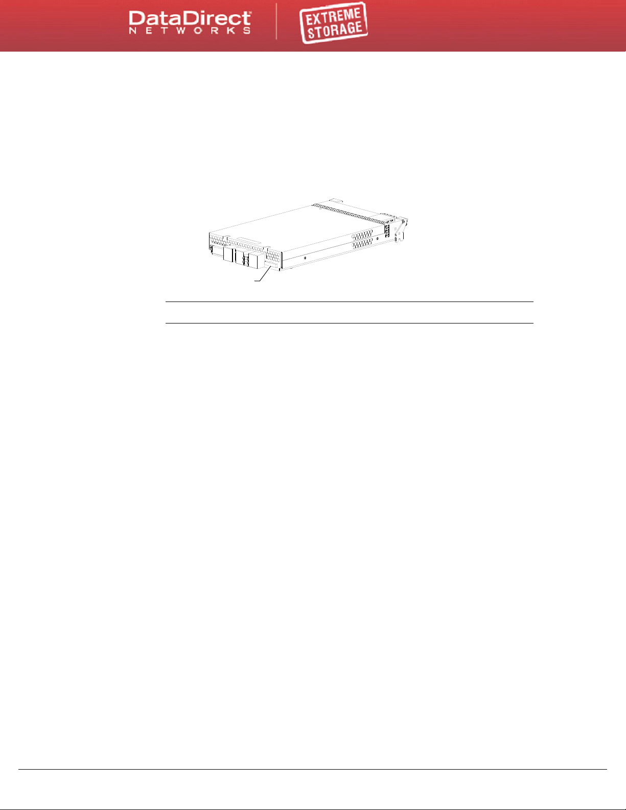
1.5 CompactFlash
CompactFlash
Figure 1. Compact Flash on Controller Module
During a power loss, data stored in cache are saved off to non-volatile memory
(CompactFlash). These data are restored to cache, and then written to disk after the issue is
corrected. CompactFlash
protect against writing incomplete data to disk, the image stored on the CompactFlash is
verified before committing to disk.
The EF3015 System Components
(Figure 1) provides unlimited cache memory backup time. To
NOTE :
Customer removal of CompactFlash will void the product warranty.
1.6 Super-Capacitor Pack
To protect controller module cache in case of power failure, each controller enclosure
model is equipped with super-capacitor technology, in conjunction with CompactFlash
memory, built into each controller module to provide unlimited cache memory backup time.
The super-capacitor pack provides energy for backing up unwritten data in the write cache
to the CompactFlash, in the event of a power failure. Unwritten data in CompactFlash
memory are automatically committed to disk media when power is restored. In the event of
power failure, while cache is maintained by the super-capacitor pack, the Cache Status LED
flashes at a rate of 1/10 second on and 9/10 second off.
EF3015 Setup Guide (Rev A)
10

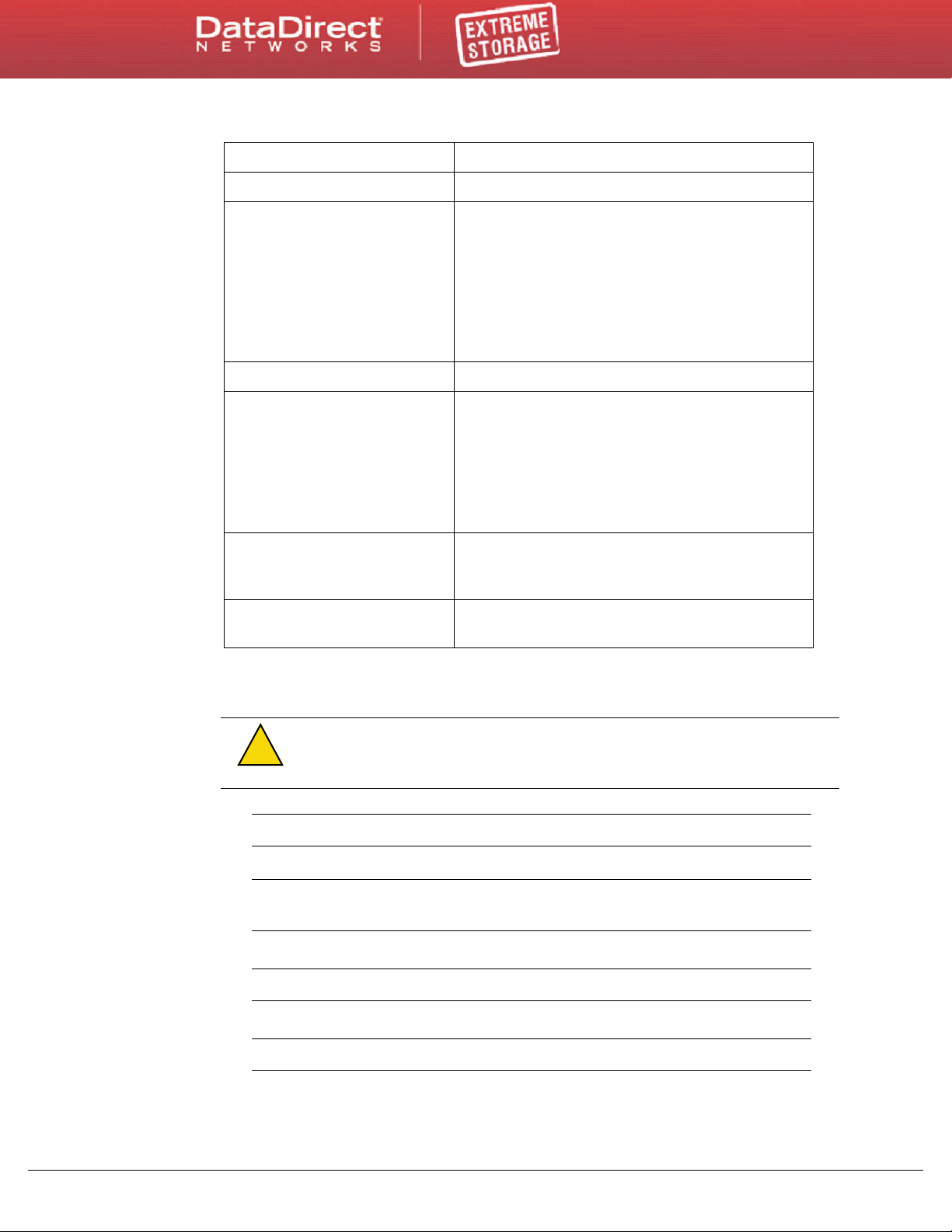
2.1 Installation Checklist
Figure 2 outlines the steps required to install the enclosures, and initially configure and
provision the storage system. To ensure successful installation, perform the tasks in the
order presented.
Figure 2. Installation Checklist
Step Task Where to find procedure
2
Installation
1. Install the controller enclosure and
optional drive enclosures in the rack, and
attach ear caps.
2. Connect power cords. See the installation sheet for your EF3015 controller
3. Install required host software. See
4. Connect hosts. See 3.3 "Connecting the Enclosure to Hosts"
5. Connect remote management hosts. See 3.6 "Connecting a Management Host on
6. Obtain IP values and set network port IP
properties on the controller enclosure.
a
7. Perform initial configuration tasks
• Sign in to the web-based storage
management application (RAIDar).
• Initially configure and provision the
system using RAIDar.
a. RAIDar is introduced in
online help for additional information.
4.1 "Accessing RAIDar" on page 27. See the RAIDar user guide or
:
See the rack-mount bracket kit installation
instructions pertaining to your enclosure.
enclosure.
3.1 "Host System Requirements" on
page 17.
on page 17.
the Network"
See 3.9 "Obtaining IP Values" on page 22.
For USB CLI port and cable use, see Appendix D.
Also see the ship kit CD.
See “Getting Started” in the EF3015 RAIDar User
Guide.
See “Configuring the System” and “Provisioning the
System” topics in the RAIDar user guide or online
help.
on page 20.
Additional installation notes:
• Controller modules within the same enclosure must be of the same type.
• For optimal performance, do not mix 6Gb and 3Gb disk drives within the enclosure.
EF3015 Setup Guide (Rev A)
11

2.2 Powering on/Powering Off
Before powering on the enclosure for the first time:
• Install all disk drives in the enclosure so the controller can identify and configure them
at power-up.
• Connect the cables and power cords to the enclosure as explained in the installation
sheet.
Installation
NOTE :
PSUs power on when connected to a power source, and power off when disconnected.
• Generally, when powering up, make sure to power up the enclosures and associated
data host in the following order:
- Drive enclosures first
- Controller enclosure next
- Data host last (if powered down for maintenance purposes).
TIP :
powering on.
Newer AC power supply units (PSUs) do not have power switches. Switchless
This ensures that the disks in the drive enclosure have enough time to completely
spin up before being scanned by the controller modules within the controller
enclosure.
While enclosures power up, their LEDs blink. After the LEDs stop blinking — if no
LEDs on the front and back of the enclosure are amber
complete, and no faults have been detected. See Appendix
page 44 for descriptions of LED behavior.
— the power-on sequence is
A "LED Descriptions" on
Depending upon the number and type of disks in the system, it may take several
minutes for the system to become ready.
Generally, when powering off, you will reverse the order of steps used for
Power cycling procedures vary according to the type of power supply unit included within
the enclosure. For controller and drive enclosures configured with switchless AC PSUs,
refer to the procedure described in 2.3 "AC PSU" below. For procedures pertaining to a)
controller enclosures configured with DC PSUs, or b) previously installed expansion
enclosures featuring power switches, see 2.4 "DC and AC PSUs with power switch" on
page 14.
EF3015 Setup Guide (Rev A)
12
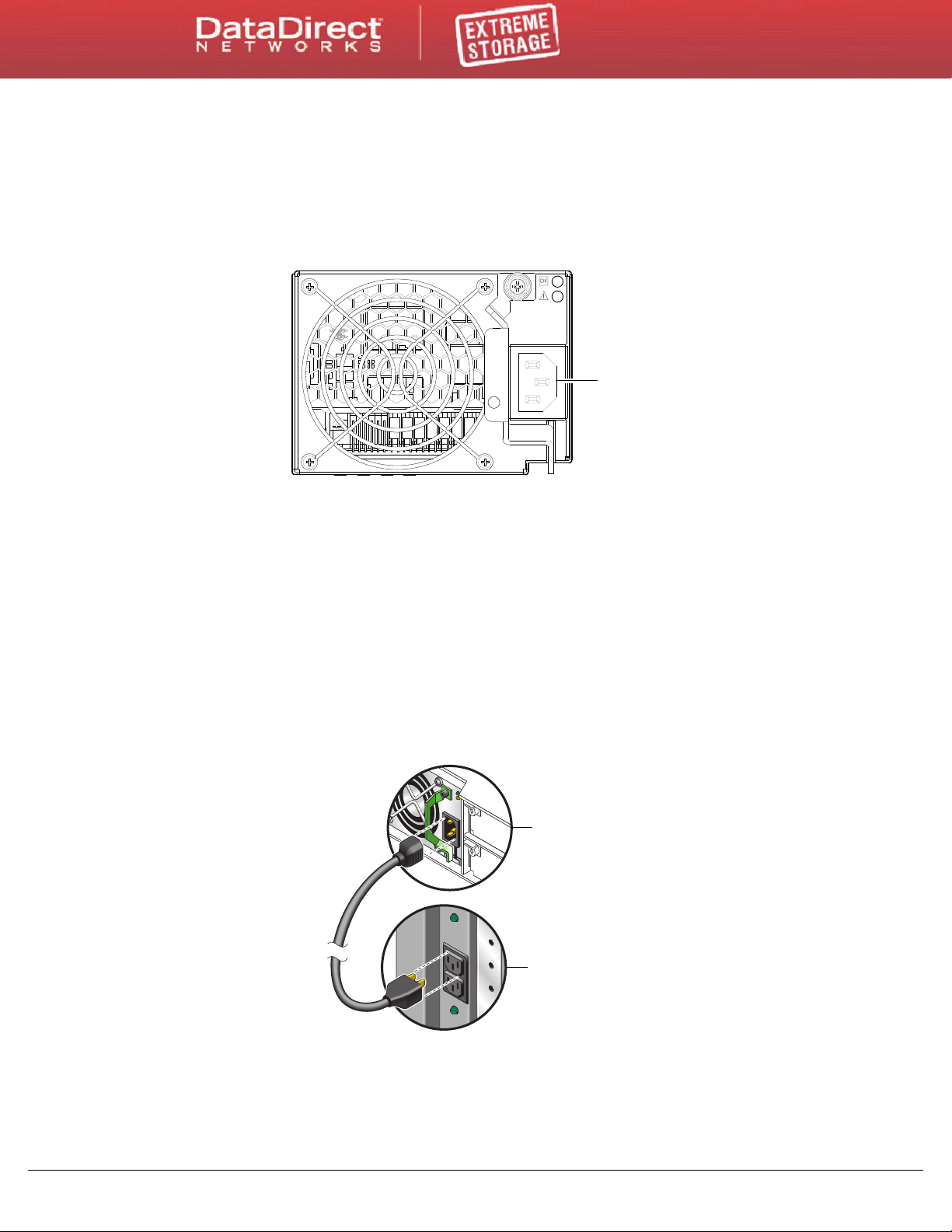
2.3 AC PSU
Power cord connect
Figure 3. AC PSU
Power supply
module
Rack power
source
Figure 4. AC Power Cord
Controller and drive enclosures configured with switchless PSUs rely on the power cord for
power cycling. Connecting the cord from the PSU power cord connector
appropriate power source facilitates power on; whereas disconnecting the cord from the
power source facilitates power off.
To power on the system:
Installation
(Figure 3) to the
1. Plug the pow
2. P
er cord into the power cord connector on the back of the drive enclosure.
Plug the other end of the power cord into the rack power source (see Figure 3 and
Figure 4). Wait several seconds to allow the disks to spin up.
Repeat this sequence for e
ach switchless PSU within each drive enclosure.
lug the power cord into the power cord connector on the back of the controller
enclosure. Plug the other end of the power cord into the rack power source (see
Figure 3 and Figure 4).
Repeat the sequence for the c
ontroller enclosure’s other switchless PSU.
EF3015 Setup Guide (Rev A)
To power off the system:
1. S
top all I/O from hosts to the system.
2. Sh
ut down both controllers using either method described below:
13
- Use RAIDar to shut down both controllers, as described in the online help and the
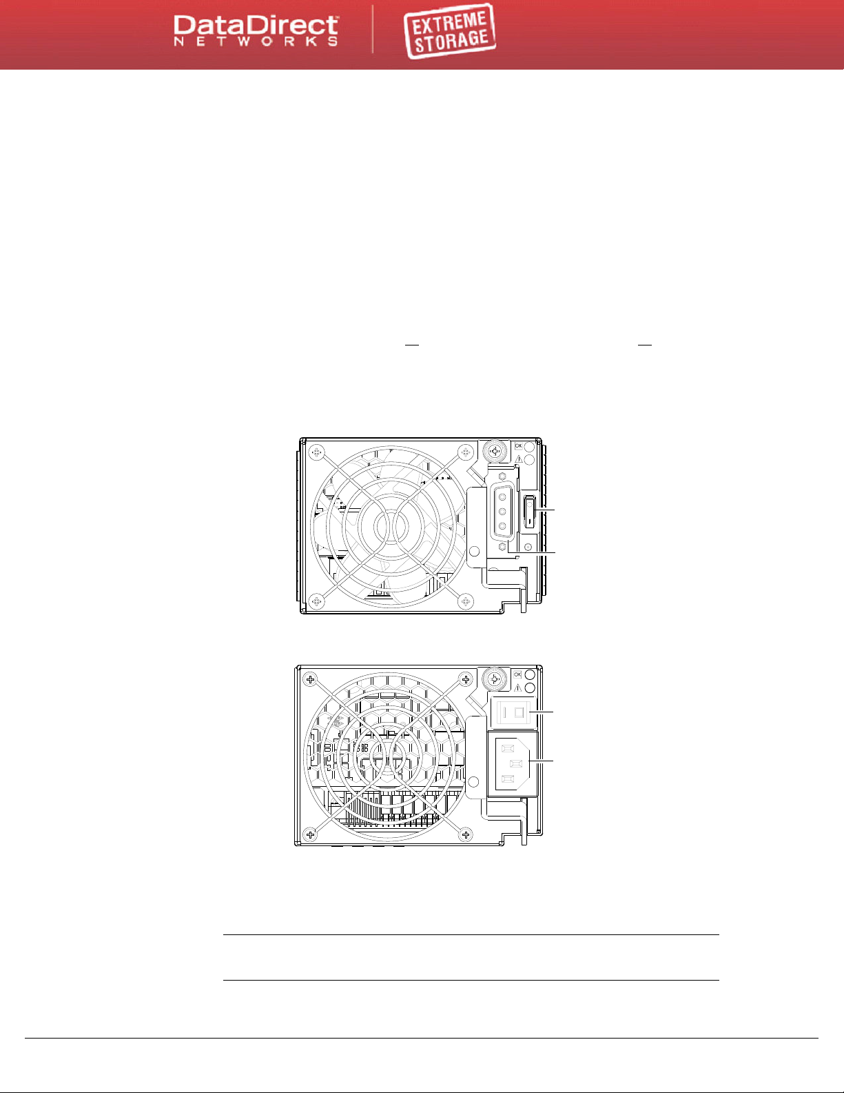
Power
switch
Power
cable
connect
Power
switch
Power
cord
connect
DC Power Supply Unit
Legacy AC Power Supply Unit
Figure 5. DC and AC PSUs with Power Switch
EF3015 RAIDar User Guide.
- Proceed to Step 3.
- Use the command line interface (CLI) to shut down both controllers, as described in
EF3015 CLI Reference Guide.
the
sconnect the power cord’s male plug from the power source.
3. Di
sconnect the power cord’s female plug from the power cord connector on the PSU.
4. Di
2.4 DC and AC PSUs with power switch
DC and legacy AC power supplies — each equipped with a power switch — are shown in
Figure 5.
Installation
2.4.1 Power Cords
IMPORTANT :
Specifications" on page 48 for additional information.
See Appendix B "Environmental Requirements &
EF3015 Setup Guide (Rev A)
14
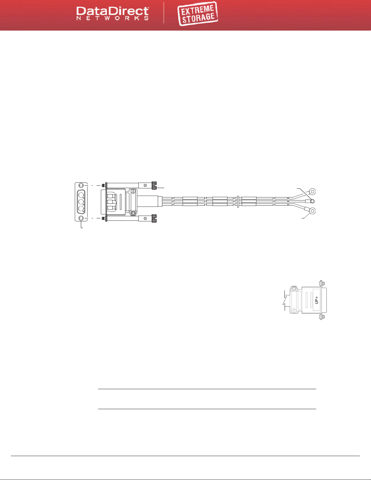
Installation
Connector (front view)
Power cable (right side view with sectioned cutaway and wire breaks)
+L
GND
-L
+L
GND
-L
+L
GND
-L
Connector pins (typical 2 places)
Ring/lug connector (typical 3 places)
(+)
(-)
Ground
Figure 6. DC Power Cable Featuring D-Shell and Lug Connectors
D-shell
(left side view)
AC model
See Figure 4 and the AC PSU shown in Figure 5 when performing the following steps:
erify that the enclosure’s power switches are in the Off position.
1. V
2. Identi
3. Usin
fy the power cord connector on the PSU, and locate the target power source.
g the AC power cords provided, plug one end of the cord into the power cord
connector on the PSU. Plug the other end of the power cord into the rack power source.
erify connection of primary power cords from the rack to separate external power
4. V
sources.
See "Power cycle".
DC model
See Figure 6 and the DC PSU shown in Figure 5 when performing the following steps:
1. Loca
te and use the provided DC power cables.
2. V
erify that the enclosure’s power switches are in the Off position.
3. Connect a
D-shell connector. Use the UP> arrow on
ensure proper positioning (see adjacent left side view of D-shell
connec
ighten the screws at the top and bottom of the shell, applying a
4. T
torque between 1.7 N-m (15 in-lb) and 2.3 N-m (20 in-lb), to securely
attach the cable to the DC power supply module.
o complete the DC connection, secure the other end of each cable wire component of
5. T
the DC power cable to the target DC power source.
Check the three individual DC cable wire labels
to its power source. One cable wire is labeled ground (GND), and the other two are
labeled positive (+L) and negative (-L), respectively
C
AUTION
nominal range (-36VDC to -72VDC) may damage the enclosure.
See "Power cycle".
EF3015 Setup Guide (Rev A)
DC power cable to each DC power supply using the
the connector shell to
tor).
before connecting each cable wire lug
(Figure 6).
:
Connecting to a DC power source outside the designated -48VDC
15

Installation
Power cycle
To power on the system:
1. Power up drive enclosure(s). Allow several seconds for disks to spin up.
Press the power switches at the back of each drive enclosure to the On position.
2. Power up the controller enclosure next.
Press the power switches at the back of the controller enclosure to the On position.
To power off the system:
1. Stop all I/O from hosts to the system.
2. Shut down both controllers using either method described below:
- Use RAIDar to shut down both controllers, as described in the online help and the
EF3015 RAIDar User Guide.
- Proceed to Step 3.
- Use the command line interface (CLI) to shut down both controllers, as described in
the EF3015 CLI Reference Guide.
3. Press the power switches at the back of the controller enclosure to the Off position.
4. Press the power switches at the back of each drive enclosure to the Off position.
EF3015 Setup Guide (Rev A)
16

3.1 Host System Requirements
Hosts connected to an EF3015 controller enclosure must meet the following requirements:
If fault tolerance is required, then multipathing software may be required. Host-based
multipath software should be used in any configuration where two logical paths
between the host and any storage volume may exist at the same time. This would
include most configurations where there are multiple connections to the host or
multiple connections between a switch and the storage.
• For Windows Server 2003, use the MPIO DSM available from DDN Support.
• Use native Microsoft MPIO DSM support with Windows Server 2008. Use either the
Server Manager or the command line interface (mpclaim CLI tool) to perform the
installation.
See the following web sites for information about using native Microsoft MPIO DSM:
http://support.microsoft.com/gp/assistsupport
http://technet.microsoft.com (search the site for “multipath I/O overview”)
3
Connecting Hosts
• To prevent Microsoft Windows 2003 hosts from displaying the Found New Hardware
Wizard when the storage system is discovered, install the SCSI Enclosure Services
driver available from DDN Support.
NOTE :
The SCSI Enclosure Services driver is required for Windows Server 2003.
3.2 Cabling Considerations
Common cabling configurations address hosts, controller enclosures, drive enclosures, and
switches. Cabling systems to enable use of the licensed AssuredRemote™ feature — to
replicate volumes — is yet another important cabling consideration. See 3.7 "Connecting
Two Storage Systems to Replicate Volumes" for more information.
Fibre Channel ports can connect to Fibre Channel hosts; or be used with AssuredRemote for
replication (licensed option).
3.3 Connecting the Enclosure to Hosts
A host identifies an external port to which the storage system is attached. Cable connections
vary depending on configuration. This section describes host interface protocols supported
by EF3015 controller enclosures, while showing a few common cable configurations.
EF3015 Setup Guide (Rev A)
17

Connecting Hosts
NOTE :
The EF3015 controllers use Unified LUN Presentation (ULP) — a controller
firmware feature enabling hosts to access mapped volumes via host ports — without
the need for internal or external switches.
3.3.1 FC Host Ports
The EF3015 controller enclosures use Fibre Channel (FC) interface protocol for host port
connection, featuring either one or two controller modules. Each controller module
provides two host ports configured with a Fibre Channel small form-factor pluggable (SFP
transceiver) connector, supporting data rates of up to 8 Gbps, with a 1.2 GHz processor and
2 GB cache.
The models referenced above support Fibre Channel Arbitrated Loop (FC-AL or “loop”)
topology by default. Connection mode can be set to loop or point-to-point. Loop protocol can
be used in a physical loop or in a direct connection between two devices. Point-to-point
protocol is used to connect to a fabric switch. The EF3015 controller enclosures can
alternatively be cabled to support replication via the FC host interface ports.
3.4 Connecting Direct Attach Configurations
The EF3015 supports up to four direct-connect server connections, two per controller
module. Connect appropriate cables from the server’s HBAs to the controller module’s host
ports as described below, and shown in Figure 7.
• To connect the EF3015 controller enclosure to a server HBA or switch — using the
controller’s FC host ports — select Fibre Channel cables supporting 2/4/8 Gb data rates,
that are compatible with the controller module‘s host port SFP connector. Such cables
are also used for connecting a local storage system to a remote storage system via a
switch, to facilitate use of the optional AssuredRemote replication feature.
• The table below maps SFP transceiver data rates to relative fiber optic cable
characteristics (i.e., cable length, multimode fiber type (MMF), and ISO/IEC optical
multimode cable performance standards). When transferring data through FC
connections, cable lengths should not exceed the lengths listed for each given fiber type
and performance code within the applicable data rate (2/4/8 Gb) class.
Figure 7. Maximum cable lengths for 850nm Fibre Channel SFP transceivers
SFP Data Representative Cable Performance Code
Data Rate MMF FC Cable Length Designator OM1 OM2 OM3
8-Gbps 21m with 62.5µm fiber type X
50m with 50µm fiber type X
150m with 50µm fiber type X
4-Gbps 70m with 62.5µm fiber type X
150m with 50µm fiber type X
380m with 50µm fiber type X
2-Gbps 150m with 62.5µm fiber type X
300m with 50µm fiber type X
500m with 50µm fiber type X
EF3015 Setup Guide (Rev A)
18
 Loading...