

DataDirect Networks EF2915 Series User Manual

EF2915 Series User Guide

P/N 801-000013 REV 53
EF2915 Series
User Guide

(C) 2002-2007 iQstor Networks, Inc. All rights reserved.
This publication, the EF2915 Series printed circuit boards, and related documentation are protected by Federal copyright law , w ith
all rights reserved. No part of this product may be copied, photocopied, reproduced, stored in a retrieval system, translated,
transcribed or transmitted, in any form or by any means manual, electric, electronic, electromagnetic, mechanical, optical or otherwise, in whole or in part without prior explicit written consent from iQstor Networks, Inc.
Included software, including all files and data, and the magnetic media on which it is contained (the “Licensed Software”), is
licensed to you, the end user, for your own internal use. You do not obtain title to the licensed software. You may not sublicense,
rent, lease, convey, modify, translate, convert to another programming language, decompile, or disassemble the licensed software
for any purpose.
You may a) only use the software on a single machine; b) copy only the software into any machine-readable or printed form for
backup in support of your use of the program on the single machine; and c) transfer the programs and license to use by another
party if the other party agrees to accept the terms and conditions of the licensing agreement. If you transfer the programs, you must
at the same time either transfer all cop ies whe ther in printed or ma chi ne- readabl e f orm to the same party or destroy any copies not
transferred.
Limitation of Liability
Information presented by DataDirect Networks, Inc. in this manual is believ ed to be accurate and reliable. However, DataDirect
Networks, Inc. assumes no responsibility for its use. No license is granted by implication or otherwi s e to any rights of DataDirect
Networks, Inc.
Product specifications and prices are subject to change without notice.
Trademark References
DataDirect Networks and the DataDirect Networks logo are registered trademarks of DataDirect Netwo rks, Inc. The EF2915
Series are trademarks of DataDirect Networks, Inc.
Sun Microsystems and Sun W orkstation are reg istered trademar ks of Sun Microsystems, Inc. Solaris, OpenWindows, and SPARCstation are trademarks of Sun Microsystems, Inc.
All SP ARC trademarks, including the SCD Compliant Logo, are tradem arks or registered trademarks of SPARC International, Inc.
UNIX is a registered trademark of AT&T.
Registered Rights Legend
Use, duplication, or disclosure by the Government is subject to restrictions as set forth in subparagraph (c)(1)(ii) of the Rights in
Technical Data and Computer Software clause at DFARS 52.227 7013 (Oct. 1988) and FAR 52.227 19(c) (Jun. 1987).
ii EF2915 Series User Guide

EF2915 Series User Guide iii
Contents
Chapter 1 About this Guide 1
Intended Audience. . . . . . . . . . . . . . . . . . . . . . . . . . . . . . . . . . . . . . . . . . . . . . . . . . . . . . . . . . . . . . 2
Organization of This Guide. . . . . . . . . . . . . . . . . . . . . . . . . . . . . . . . . . . . . . . . . . . . . . . . . . . . . . . 2
Notes, Cautions, and Warnings . . . . . . . . . . . . . . . . . . . . . . . . . . . . . . . . . . . . . . . . . . . . . . . . . . . . 3
Typographical Conventions. . . . . . . . . . . . . . . . . . . . . . . . . . . . . . . . . . . . . . . . . . . . . . . . . . . . . . . 4
DataDirect Networks Welcomes Your Comments . . . . . . . . . . . . . . . . . . . . . . . . . . . . . . . . . . . . . 4
Chapter 2 The EF2915 Series Storage System 5
What Is the DataDirect Networks SAN Solution? . . . . . . . . . . . . . . . . . . . . . . . . . . . . . . . . . . . . . 6
Java-Based Graphical User Interface. . . . . . . . . . . . . . . . . . . . . . . . . . . . . . . . . . . . . . . . . . . . . . . . 6
Before You Begin . . . . . . . . . . . . . . . . . . . . . . . . . . . . . . . . . . . . . . . . . . . . . . . . . . . . . . . . . . . . . . 6
SAN Overview. . . . . . . . . . . . . . . . . . . . . . . . . . . . . . . . . . . . . . . . . . . . . . . . . . . . . . . . . . . . . . . . . 7
Elements of a SAN . . . . . . . . . . . . . . . . . . . . . . . . . . . . . . . . . . . . . . . . . . . . . . . . . . . . . . . . . 8
Example – Fibre Channel SAN. . . . . . . . . . . . . . . . . . . . . . . . . . . . . . . . . . . . . . . . . . . . . . . . 9
Fibre Channel Overview . . . . . . . . . . . . . . . . . . . . . . . . . . . . . . . . . . . . . . . . . . . . . . . . . . . . . . . . 10
Who is Fibre Channel? . . . . . . . . . . . . . . . . . . . . . . . . . . . . . . . . . . . . . . . . . . . . . . . . . . . . . 11
How Does it Work?. . . . . . . . . . . . . . . . . . . . . . . . . . . . . . . . . . . . . . . . . . . . . . . . . . . . . . . . 11
Fibre Channel Topologies . . . . . . . . . . . . . . . . . . . . . . . . . . . . . . . . . . . . . . . . . . . . . . . . . . . 12
Types of Fibre Channel Ports . . . . . . . . . . . . . . . . . . . . . . . . . . . . . . . . . . . . . . . . . . . . . . . . 12
Fibre Channel Standards . . . . . . . . . . . . . . . . . . . . . . . . . . . . . . . . . . . . . . . . . . . . . . . . . . . . 13
Introduction to RAID Technology. . . . . . . . . . . . . . . . . . . . . . . . . . . . . . . . . . . . . . . . . . . . . . . . . 14
RAID Level 0 . . . . . . . . . . . . . . . . . . . . . . . . . . . . . . . . . . . . . . . . . . . . . . . . . . . . . . . . . . . . 14
RAID Level 1 . . . . . . . . . . . . . . . . . . . . . . . . . . . . . . . . . . . . . . . . . . . . . . . . . . . . . . . . . . . . 15
RAID Level 1+0 . . . . . . . . . . . . . . . . . . . . . . . . . . . . . . . . . . . . . . . . . . . . . . . . . . . . . . . . . . 15
RAID Level 3 . . . . . . . . . . . . . . . . . . . . . . . . . . . . . . . . . . . . . . . . . . . . . . . . . . . . . . . . . . . . 16
RAID Level 5 . . . . . . . . . . . . . . . . . . . . . . . . . . . . . . . . . . . . . . . . . . . . . . . . . . . . . . . . . . . . 17
RAID Level 50 . . . . . . . . . . . . . . . . . . . . . . . . . . . . . . . . . . . . . . . . . . . . . . . . . . . . . . . . . . . 18
RAID Level 6 . . . . . . . . . . . . . . . . . . . . . . . . . . . . . . . . . . . . . . . . . . . . . . . . . . . . . . . . . . . . 19
Key Terms Used in This Guide. . . . . . . . . . . . . . . . . . . . . . . . . . . . . . . . . . . . . . . . . . . . . . . . . . . 21
EF2915 Series Specifications . . . . . . . . . . . . . . . . . . . . . . . . . . . . . . . . . . . . . . . . . . . . . . . . . . . . 23
Chapter 3 Setting Up the EF2915 Series System 25
Selecting an Installation Location . . . . . . . . . . . . . . . . . . . . . . . . . . . . . . . . . . . . . . . . . . . . . . . . . 26
Environmental Requirements . . . . . . . . . . . . . . . . . . . . . . . . . . . . . . . . . . . . . . . . . . . . . . . . 26

iv EF2915 Series User Guide
Contents
Air Flow. . . . . . . . . . . . . . . . . . . . . . . . . . . . . . . . . . . . . . . . . . . . . . . . . . . . . . . . . . . . . . . . . 26
Input Power . . . . . . . . . . . . . . . . . . . . . . . . . . . . . . . . . . . . . . . . . . . . . . . . . . . . . . . . . . . . . . 26
Unpacking the EF2915 . . . . . . . . . . . . . . . . . . . . . . . . . . . . . . . . . . . . . . . . . . . . . . . . . . . . . . . . . 27
Installing the EF2915 in a Cabinet using the RK12 Kit . . . . . . . . . . . . . . . . . . . . . . . . . . . . . . . . 28
Assembling the RK12 Kit . . . . . . . . . . . . . . . . . . . . . . . . . . . . . . . . . . . . . . . . . . . . . . . . . . . 28
Cable Connections . . . . . . . . . . . . . . . . . . . . . . . . . . . . . . . . . . . . . . . . . . . . . . . . . . . . . . . . . . . . 30
In a Cabinet . . . . . . . . . . . . . . . . . . . . . . . . . . . . . . . . . . . . . . . . . . . . . . . . . . . . . . . . . . . . . . 30
Power Connection . . . . . . . . . . . . . . . . . . . . . . . . . . . . . . . . . . . . . . . . . . . . . . . . . . . . . . . . . 30
Connecting to EXP2915 Expansion Enclosures . . . . . . . . . . . . . . . . . . . . . . . . . . . . . . . . . . 31
Setting the Fibre Channel Loop Rate on the EF2915 . . . . . . . . . . . . . . . . . . . . . . . . . . . . . . 32
Configuring the Fibre Channel Interface of a EXP2915. . . . . . . . . . . . . . . . . . . . . . . . . . . . 32
Serial Port Connection and Configuration. . . . . . . . . . . . . . . . . . . . . . . . . . . . . . . . . . . . . . . 34
IP Connection . . . . . . . . . . . . . . . . . . . . . . . . . . . . . . . . . . . . . . . . . . . . . . . . . . . . . . . . . . . . 38
Fibre Channel Connection. . . . . . . . . . . . . . . . . . . . . . . . . . . . . . . . . . . . . . . . . . . . . . . . . . . 40
Enclosure Configuration . . . . . . . . . . . . . . . . . . . . . . . . . . . . . . . . . . . . . . . . . . . . . . . . . . . . . . . . 41
Using the System Manager . . . . . . . . . . . . . . . . . . . . . . . . . . . . . . . . . . . . . . . . . . . . . . . . . . 41
Configuring a Management Console. . . . . . . . . . . . . . . . . . . . . . . . . . . . . . . . . . . . . . . . . . . . . . . 42
MPC Hardware Description . . . . . . . . . . . . . . . . . . . . . . . . . . . . . . . . . . . . . . . . . . . . . . . . . 42
MPC Software Description . . . . . . . . . . . . . . . . . . . . . . . . . . . . . . . . . . . . . . . . . . . . . . . . . . 42
Minimum MPC Requirements. . . . . . . . . . . . . . . . . . . . . . . . . . . . . . . . . . . . . . . . . . . . . . . . 43
DataDirect Networks SAN Manager Software Installation. . . . . . . . . . . . . . . . . . . . . . . . . . 43
DataDirect Networks SAN Manager Software Setup Verification. . . . . . . . . . . . . . . . . . . . 43
DataDirect Networks SAN Storage Product Support . . . . . . . . . . . . . . . . . . . . . . . . . . . . . . 44
DataDirect Networks SAN Manager Functions . . . . . . . . . . . . . . . . . . . . . . . . . . . . . . . . . . 44
Front Panel. . . . . . . . . . . . . . . . . . . . . . . . . . . . . . . . . . . . . . . . . . . . . . . . . . . . . . . . . . . . . . . . . . . 45
LCD Information. . . . . . . . . . . . . . . . . . . . . . . . . . . . . . . . . . . . . . . . . . . . . . . . . . . . . . . . . . 45
EF2915 LCD Guide. . . . . . . . . . . . . . . . . . . . . . . . . . . . . . . . . . . . . . . . . . . . . . . . . . . . . . . . 46
LED Indicators. . . . . . . . . . . . . . . . . . . . . . . . . . . . . . . . . . . . . . . . . . . . . . . . . . . . . . . . . . . . . . . . 48
Rear Panel – EF2915. . . . . . . . . . . . . . . . . . . . . . . . . . . . . . . . . . . . . . . . . . . . . . . . . . . . . . . . . . . 49
SP2xx Storage Processors . . . . . . . . . . . . . . . . . . . . . . . . . . . . . . . . . . . . . . . . . . . . . . . . . . . . . . . 50
Probing the EF2915. . . . . . . . . . . . . . . . . . . . . . . . . . . . . . . . . . . . . . . . . . . . . . . . . . . . . . . . . . . . 50
From a Solaris Host. . . . . . . . . . . . . . . . . . . . . . . . . . . . . . . . . . . . . . . . . . . . . . . . . . . . . . . . 50
From a Windows Host. . . . . . . . . . . . . . . . . . . . . . . . . . . . . . . . . . . . . . . . . . . . . . . . . . . . . . 50
Chapter 4 Database Application Agent for Oracle, SQL and Exchange51
Overview . . . . . . . . . . . . . . . . . . . . . . . . . . . . . . . . . . . . . . . . . . . . . . . . . . . . . . . . . . . . . . . . . . . . 51
Oracle on a Windows Server. . . . . . . . . . . . . . . . . . . . . . . . . . . . . . . . . . . . . . . . . . . . . . . . . . . . . 51
Installation . . . . . . . . . . . . . . . . . . . . . . . . . . . . . . . . . . . . . . . . . . . . . . . . . . . . . . . . . . . . . . . 51
Start Up . . . . . . . . . . . . . . . . . . . . . . . . . . . . . . . . . . . . . . . . . . . . . . . . . . . . . . . . . . . . . . . . . 51
Oracle on a Solaris Server. . . . . . . . . . . . . . . . . . . . . . . . . . . . . . . . . . . . . . . . . . . . . . . . . . . . . . . 53
Installation . . . . . . . . . . . . . . . . . . . . . . . . . . . . . . . . . . . . . . . . . . . . . . . . . . . . . . . . . . . . . . . 53
Start Up . . . . . . . . . . . . . . . . . . . . . . . . . . . . . . . . . . . . . . . . . . . . . . . . . . . . . . . . . . . . . . . . . 53
Exchange on a Windows Server . . . . . . . . . . . . . . . . . . . . . . . . . . . . . . . . . . . . . . . . . . . . . . . . . . 54
Working Mode. . . . . . . . . . . . . . . . . . . . . . . . . . . . . . . . . . . . . . . . . . . . . . . . . . . . . . . . . . . . 54
Installation . . . . . . . . . . . . . . . . . . . . . . . . . . . . . . . . . . . . . . . . . . . . . . . . . . . . . . . . . . . . . . . 54
Doing Backup . . . . . . . . . . . . . . . . . . . . . . . . . . . . . . . . . . . . . . . . . . . . . . . . . . . . . . . . . . . . 54

Contents
EF2915 Series User Guide v
Doing Restore . . . . . . . . . . . . . . . . . . . . . . . . . . . . . . . . . . . . . . . . . . . . . . . . . . . . . . . . . . . . 55
SQL Server on Windows. . . . . . . . . . . . . . . . . . . . . . . . . . . . . . . . . . . . . . . . . . . . . . . . . . . . . . . . 56
Working Mode. . . . . . . . . . . . . . . . . . . . . . . . . . . . . . . . . . . . . . . . . . . . . . . . . . . . . . . . . . . . 56
Installation . . . . . . . . . . . . . . . . . . . . . . . . . . . . . . . . . . . . . . . . . . . . . . . . . . . . . . . . . . . . . . . 56
Doing Backup . . . . . . . . . . . . . . . . . . . . . . . . . . . . . . . . . . . . . . . . . . . . . . . . . . . . . . . . . . . . 56
Do Restore. . . . . . . . . . . . . . . . . . . . . . . . . . . . . . . . . . . . . . . . . . . . . . . . . . . . . . . . . . . . . . . 57
Chapter 5 Troubleshooting 59
Problem Indications. . . . . . . . . . . . . . . . . . . . . . . . . . . . . . . . . . . . . . . . . . . . . . . . . . . . . . . . . . . . 59
EF2915 cannot be turned on . . . . . . . . . . . . . . . . . . . . . . . . . . . . . . . . . . . . . . . . . . . . . . . . . 60
EF2915 does not respond . . . . . . . . . . . . . . . . . . . . . . . . . . . . . . . . . . . . . . . . . . . . . . . . . . . 60
No raid; prompt from the EF2915 . . . . . . . . . . . . . . . . . . . . . . . . . . . . . . . . . . . . . . . . . . . . . 60
Host cannot probe the EF2915 by format command. . . . . . . . . . . . . . . . . . . . . . . . . . . . . . . 60
DataDirect Networks SAN Manager cannot detect the EF2915 on the Fibre Channel. . . . . 61
SFP connectivity problem . . . . . . . . . . . . . . . . . . . . . . . . . . . . . . . . . . . . . . . . . . . . . . . . . . . 62
SP2xx Storage Processor modules: No Interlink communication. . . . . . . . . . . . . . . . . . . . . 62
Ethernet connection cannot be established . . . . . . . . . . . . . . . . . . . . . . . . . . . . . . . . . . . . . . 64
RAID Configuration Warning. . . . . . . . . . . . . . . . . . . . . . . . . . . . . . . . . . . . . . . . . . . . . . . . 64
Chapter 6 Servicing the EF2915 Series System 65
Identifying Field Replaceable Units . . . . . . . . . . . . . . . . . . . . . . . . . . . . . . . . . . . . . . . . . . . . . . . 66
Inserting SFPs . . . . . . . . . . . . . . . . . . . . . . . . . . . . . . . . . . . . . . . . . . . . . . . . . . . . . . . . . . . . . . . . 67
Replacing a Faulty Disk Drive . . . . . . . . . . . . . . . . . . . . . . . . . . . . . . . . . . . . . . . . . . . . . . . . . . . 68
Drive Slots and Locations . . . . . . . . . . . . . . . . . . . . . . . . . . . . . . . . . . . . . . . . . . . . . . . . . . . 68
Removal. . . . . . . . . . . . . . . . . . . . . . . . . . . . . . . . . . . . . . . . . . . . . . . . . . . . . . . . . . . . . . . . . 68
Insertion. . . . . . . . . . . . . . . . . . . . . . . . . . . . . . . . . . . . . . . . . . . . . . . . . . . . . . . . . . . . . . . . . 68
Removing and Replacing Power Supplies. . . . . . . . . . . . . . . . . . . . . . . . . . . . . . . . . . . . . . . . . . . 70
Replacement . . . . . . . . . . . . . . . . . . . . . . . . . . . . . . . . . . . . . . . . . . . . . . . . . . . . . . . . . . . . . 71
Removing and Replacing Processor Modules. . . . . . . . . . . . . . . . . . . . . . . . . . . . . . . . . . . . . . . . 72
Removal. . . . . . . . . . . . . . . . . . . . . . . . . . . . . . . . . . . . . . . . . . . . . . . . . . . . . . . . . . . . . . . . . 72
Processor Memory. . . . . . . . . . . . . . . . . . . . . . . . . . . . . . . . . . . . . . . . . . . . . . . . . . . . . . . . . 74
Replacement . . . . . . . . . . . . . . . . . . . . . . . . . . . . . . . . . . . . . . . . . . . . . . . . . . . . . . . . . . . . . 74
Removing and Replacing Fan Modules. . . . . . . . . . . . . . . . . . . . . . . . . . . . . . . . . . . . . . . . . . . . . 76
Replacement . . . . . . . . . . . . . . . . . . . . . . . . . . . . . . . . . . . . . . . . . . . . . . . . . . . . . . . . . . . . . 78
Removing and Replacing the EMIO Module . . . . . . . . . . . . . . . . . . . . . . . . . . . . . . . . . . . . . . . . 79
Removing and Replacing Battery Module . . . . . . . . . . . . . . . . . . . . . . . . . . . . . . . . . . . . . . . . . . 81
Chapter 7 Glossary 83
Index 87

vi EF2915 Series User Guide

Chapter
About this Guide
This chapter contains information on the contents and organization of this user guide
including the intended audience, use of note, caution, and warning symbols, and
typographical conventions.
1
EF2915 Series User Guide 1

Chapter 1: About this Guide
Intended Audience
Intended Audience
This User Guide is intended for the system administrator with experience in installing
network storage or other hardware devices and configuring the system environment.This
User Guide explains how to install, connect, configure, and troubleshoot your EF2915
Series storage system.
Organization of This Guide
This User Guide contains the following chapters.
Table 1-1. Organization of This User Guide
Chapter Description
Chapter 1, “About this Guide.” Contains information on the contents, organization, and
intended audience of this guide as well as information
on the typographical conventions used in this guide.
Chapter 2, “The EF2915 Series Storage System.” Contains an introduction to DataDirect Networks
Networks SAN solutions as well as an introduction to
SAN and Fiber Channel technology, and RAID
technology. This chapter also contains a list of key
terms and specifications.
Chapter 3, “Setting Up the EF2915 Series System.” Contains information on installing and connecting the
system, starting it up, the front and rear panels, LED
indicators, serial port configuration, and probing and
testing the EF2915.
Chapter 4, “Database Application Agent for Oracle,
SQL and Exchange.”
Chapter 5, “Troubleshooting.” Contains troubleshooting information on potential
Chapter 6, “Servicing the EF2915 Series System.” Contains information on servicing your system
Chapter 7, “Glossary.” Contains a list of terms including terms related to SAN
Describes how to install and start up the Database
Application Agent for Oracle.
problems encountered when powering up and using the
system.
including removal and replacement of disk drives,
power supplies, SP288 or SP228 storage processors,
and fan modules.
and Fiber Channel technology.
“Index” Contains an index listing.
2 EF2915 Series User Guide

Notes, Cautions, and Warnings
This User Guide identifies important user information as Note, Caution, or Warning.
Note: It provides information on the current topic that is especially important to correct
operation.
Chapter 1: About this Guide
Notes, Cautions, and Warnings
!
Caution: Explains situations where damage to the equipment could result if a procedure
is not followed correctly.
Warning: Indicates that hazardous voltages or potential system damage could occur if a
procedure is not followed correctly.
EF2915 Series User Guide 3

Chapter 1: About this Guide
Typographical Conventions
Typographical Conventions
This User Guide includes the following typographical aids.
Table 1-2. Typographical Conventions
Example Usage
User Guide
“Topic Heading”
.\Firmware
-iosize
#admintool
#>ssmon -i -d
<Ctrl>
Titles of chapters or books.
Topic headings within chapters.
Directory and file names.
Emphasis to highlight terms within text, including parameter
names, new terms, and important advisements in CAUTION and
WARNING! statements.
Messages you see on the screen.
Text and values you enter at the keyboard, or the names of
window and menu selections.
A key that is pressed.
DataDirect Networks Welcomes Your Comments
We are interested in improving our documentation and welcome your comments and
suggestions.
You can email or fax your comments to us. Please include title and revision number of
your document in the subject line of your email or fax message.
• Email: support@datadirectnet.com
• Fax: 818-700-7677
4 EF2915 Series User Guide

Chapter
2
The EF2915 Series Storage System
Congratulations on selecting the DataDirect Networks Inc. EF2915 Series for your storage
area network (SAN). Your storage system provides:
• Up to 15 hot-swappable, high-performance Fibre Channel or SATA disk drives.
• Disk drives configurable as RAID sets of level 0, 1, 1+0, 3, 5, 50, or 6.
• System administration using the DataDirect Networks SAN Manager (see the
Administration and Operations User Guide).
• Dual field serviceable RAID storage processors.
• Auto-repair ability to reconstruct data on failed drives.
• Fibre Channel, iSCSI, Ethernet, and serial ports for host attachment and
administration.
• Hot-swappable power supplies with fail-over capability providing data protection in
the event of a power supply failure.
• Hot-swappable fan assemblies.
• System monitoring and configuration using the DataDirect Networks System
Manager (refer to the DataDirect Networks System Manager User Guide).
EF2915 Series User Guide 5

Chapter 2: The EF2915 Series Storage System
What Is the DataDirect Networks SAN Solution?
What Is the DataDirect Networks SAN Solution?
A typical DataDirect Networks storage system SAN solution includes:
• DataDirect Networks RAID (Redundant Array of Independent Disks) sub-systems.
They are connected to servers using Fibre Channel or iSCSI Host Bus Adapters
(HBAs). The RAID provides high availability and high performance data access.
• DataDirect Networks RAID storage processors are used to control the operation of the
RAIDs.
• System administrators configure and manage the DataDirect Networks SAN Solution
either locally or through the network.
• DataDirect Networks SAN Solutions: Fibre Channel backends and SATA backends.
Java-Based Graphical User Interface
The DataDirect Networks SAN Manager is a browser-based Graphical User Interface
(GUI). It provides an easy way to manage DataDirect Networks RAID storage systems on
a network. With simple point-and-click selections, a system administrator can configure,
maintain, and monitor DataDirect Networks devices, without having to use a terminal
command-line interface.
The DataDirect Networks SAN Manager is a central storage management utility software
that provides storage system administrators with powerful and easy-to-use storage
management capability. The DataDirect Networks SAN Manager performs Fibre channel
device discovery, offers a graphical topology map, and enables the IT administrator to
monitor, dynamically configure, and manage a network of DataDirect Networks storage
systems.
Before You Begin
The following sections provide an overview of SAN, Fibre Channel, iSCSI, and RAID
concepts and functions. An understanding of RAID/JBOD general principles can help you
get the most out of the DataDirect Networks EF2915 Series storage system. For detailed
descriptions of all DataDirect Networks storage subsystem configuration options and
parameters, see your Administration and Operations User Guide.
You can configure and manage the DataDirect Networks storage system using any of the
three management tools described in your Administration and Operations User Guide: the
DataDirect Networks SAN Manager, the command-line interface (CLI), or the ASCII
GUI, SNMP, or Telnet.
For further information about DataDirect Networks RAID products, visit our web site at
www.datadirectnet.com
.
6 EF2915 Series User Guide

SAN Overview
The explosion of corporate computer use and the reliance upon computers to store all
types of data has created the data storage industry. According to recent studies, the data
storage demands of corporations is doubling every six to nine months.
Until recently, data storage was achieved by the Direct Attached Storage, a method in
which storage devices were directly connected to servers. Network Attached Storage is a
newer approach to data storage that utilizes the advantages of a network topology,
allowing many servers and storage devices to be inter-connected.
These new storage networks are called Storage Area Networks or SANs. A SAN is a
collection of storage devices, servers, Fibre Channel switches, and other devices such as
routers. Each device performs a different function within the SAN toward the same
objective: allowing highly efficient, fast, and reliable storage of data. See “Elements of a
SAN” below for more information on the different elements (devices) that comprise a
SAN.
The storage devices (disk drives, optical or tape drives), appear to the switches and servers
as though they are directly connected (local) storage devices. Connecting a storage device
to a SAN allows any other device on the SAN to use it for storage purposes. The devices
announce or register their presence on the network so that the servers are aware of their
presence, and know the number and location of the storage devices on the network (see
“Fabric” on page 12 for more details).
Chapter 2: The EF2915 Series Storage System
SAN Overview
EF2915 Series User Guide 7

Chapter 2: The EF2915 Series Storage System
SAN Overview
Elements of a SAN
Each type of network requires different devices or elements in order to provide the desired
functionality of that network. The list below describes the various elements that comprise
a SAN.
• Switches: Fibre Channel or Gigabit Ethernet switches are essential in a network
because a network is defined as a SAN that consists of one or more switches. In
networks, the switches are used to connect numerous servers and storage devices. The
switches themselves can be connected together to create very large SANs with
millions of nodes.
• Routers: Although routers are not essential for a SAN, they are used to connect serial
SCSI and parallel SCSI devices. This is necessary when older tape drives or disk
drives are part of the SAN.
• Storage Devices: Storage devices are essential to a SAN because they provide the
storage for the SAN. The arrays are storage devices.
• Tape Systems: Tape systems can be part of a SAN if you want to share them with
servers (this makes the tape systems more accessible). Tape systems are usually
connected to the SAN through routers.
• Servers: The servers are essential to SANs because they distribute the data that is
transferred across the SAN for the purpose of storage. The intended destination of the
data is the storage devices. Servers in a fabric are connected through Fibre Channel
switches.
• Host Bus Adaptors (HBAs): HBAs (or Fibre Channel or iSCSI cards), are located on
the servers and are used to connect the network cables to the servers.
• Hubs: Hubs are used in arbitrated loop Fibre Channel topologies and are connected to
servers.
• Management Software: Although you can have all of the physical devices for a SAN
without software, the functionality of the devices cannot be utilized without a
management tool. The DataDirect SAN Manager is the software you use to manage
your SAN. See your Administration and Operations User Guide for details.
For a diagram showing an example of a Fibre Channel SAN, see Figure 2-1 on page 9.
8 EF2915 Series User Guide
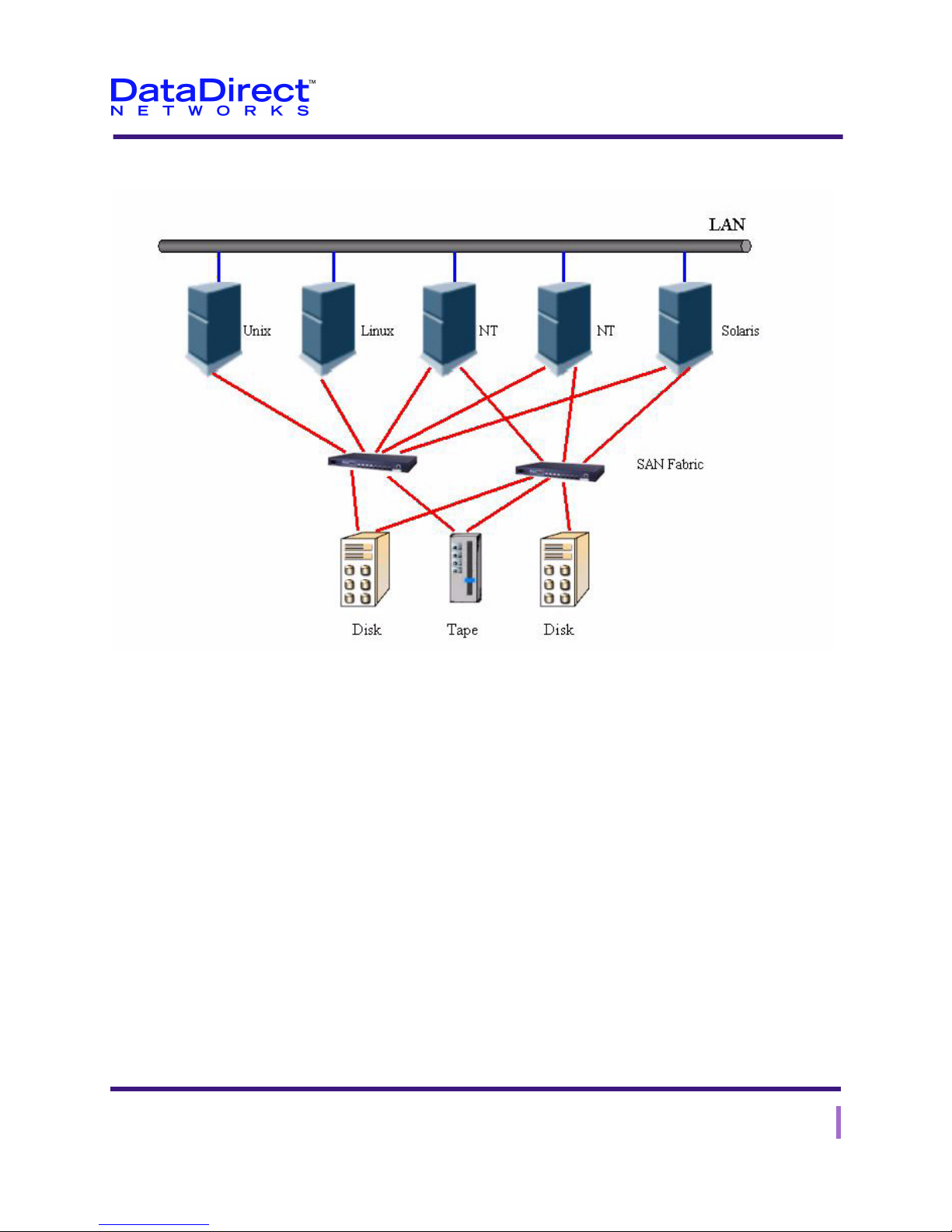
Example – Fibre Channel SAN
Chapter 2: The EF2915 Series Storage System
SAN Overview
Figure 2-1. Fibre Channel SAN Example
EF2915 Series User Guide 9

Chapter 2: The EF2915 Series Storage System
Fibre Channel Overview
Fibre Channel Overview
Fibre Channel is a set of standards that defines a layered architecture that transfers data
(the layers are referred to in the standards by number such as FC-0). Due to this
technology specific numbering scheme, the layer numbers in the Fibre Channel standards
do not correspond to the layer numbers in the OSI networking model.
The layers of the Fibre Channel architecture are:
• FC-0: This layer defines the various media types that can carry Fibre Channel data.
• FC-1: This layer defines how frames are encoded and decoded for transport across the
various media types defined in FC-0.
• FC-2: This layer defines how data from upper-level applications is segmented into
frames for transport over the lower layers.
• FC-3: This layer is currently under development and is intended to be used by
applications that require multiple ports.
• FC-4: This layer defines how a Fibre Channel network communicates with upper-
level applications (such as SCSI and IP).
Fibre Channel was designed to eliminate the performance restrictions of LANs, and is
now the technology of choice for applications that require high reliability, high bandwidth,
and scalability. The Fibre Channel architecture is a channel/network integration in which
the communication between the network devices is dynamic and intelligent. The
transmission of data within the network is separate from the controlling protocol so that
various topologies (point-to-point links, arbitrated loops, or switched) can be used based
on a particular Fibre Channel implementation. Since the Fibre Channel network is selfmanaged, there is no need for controlling stations at each node which reduces the
complexity of the implementation.
The features of Fibre Channel technology that increase network performance over
traditional LANs include:
• Automatic self-discovery of all Fibre Channel topologies (point-to-point links,
arbitrated loops, or switched).
• Support for traditional network self-discovery including ARP, RARP, and other self-
discovery protocols.
• Support for dedicated bandwidth point-to-point, shared bandwidth, and scalable
bandwidth switched circuits.
• The ability to bypass the protocol stack for increased performance.
• Confirmed delivery of data to increase reliability.
• QoS (quality of service) support such as connection-based virtual circuits and
fractional bandwidth to ensure bandwidth for the storing of data (and other
operations).
10 EF2915 Series User Guide

• The time to establish (setup) circuits is measured in microseconds using hardware
enhanced Fibre Channel protocol.
• Highly efficient and low-latency data transfer using variable length frames.
• Support for time sensitive applications such as video through the use of fractional
bandwidth virtual circuits.
• Efficient, high-bandwidth, and low-latency data transfer using variable length frames.
Who is Fibre Channel?
Currently, several groups are attempting to standardize Fibre Channel and SAN
technology. These groups include:
• Storage Networking Industry Association (SNIA): www.snia.org.
• Fibre Channel Industry Association (FCIA): www.fibrechannel.com.
• Fibre Alliance (www.fibrealliance.org).
Chapter 2: The EF2915 Series Storage System
Fibre Channel Overview
How Does it Work?
These steps provide a brief outline of how data is transferred across a Fibre Channel
network as part of the data storage process.
1 A server requests that the data be transferred to an DataDirect Networks storage
device, through the Fibre Channel network.
2 The data is then segmented into frames and encoded, and sent across the network with
the disk drives as the intended destination. The data may travel through various types
of devices (for example, switches, hubs, or routers), and through either fiber optic or
copper cable.
3 The data finally arrives at the port to which the disk drive is attached.
4 The frames are decoded for transfer to the disk drive.
5 The return frames are encoded and assembled for return to the application.
EF2915 Series User Guide 11

Chapter 2: The EF2915 Series Storage System
Fibre Channel Overview
Fibre Channel Topologies
There are three Fibre Channel network topologies, the simplest and least expensive of
which is the point-to-point topology. The second topology is the arbitrated loop which is
more complex and expensive than point-to-point and offers much more functionality. The
third topology is the fabric which offers the most functionality and is the most complex
and expensive. These different Fibre Channel typologies are described below.
Point-to-Point
This topology involves only two devices which are usually a server and a storage device,
with no devices existing between them. This topology is found in first generation
implementations of Fibre Channel.
Arbitrated Loop
This topology involves multiple devices that share a common medium. Not only does this
topology involve many more devices than point-to-point, but each device must arbitrate
for access and use of the shared medium. Arbitration ensures that the devices gain access
to and use the shared medium in an orderly and controlled manner. This topology is
similar to Token Ring in networking.
Fabric
This topology involves numerous devices but is characterized by having one or more Fibre
Channel switches in the same network. The storage devices announce or register their
presence on the fabric to the switches using the SNS (simple name server) databases that
reside on the servers. The SNS database includes the device’s network address, WWN
(world wide name), and other information that helps identify the device.
In order for the servers to know the number and location of the storage devices on the
network, each server queries the SNS database to discover the storage devices (switches
exchange SNS data so that each server has the information to discover the storage devices
on the network).
Types of Fibre Channel Ports
There are three basic Fibre Channel port types: the N_Port, the F_Port, and the E_Port.
Once arbitrated loop capabilities are added, the port names change to reflect this. These
ports are described below.
• N_Port: A node port, or a port on a Fibre Channel disk or computer. These types of
ports only communicate with another N_Port on a different node, or with a switch.
• F_Port: A fabric port (these can only be switch ports). These types of ports can only
be connected to an N_Port in a point-to-point connection.
12 EF2915 Series User Guide

• E_Port: An expansion port on a switch that is used to connect to another E_Port on a
different switch (this type of connection is used to connect devices to create a large
fabric).
• NL_Port: A node port with arbitrated loop capability. These ports are only found on
Fibre Channel switches, but can connect to other nodes or to an arbitrated loop.
• FL_Port: A fabric port with arbitrated loop capability. These ports are connected to
other nodes, to a switch, or to an arbitrated loop.
• G_Port: A generic port on a Fibre Channel switch that can function as an E-Port, an
FL_Port, or an F-Port. The function of the port is based on how the port is connected.
Fibre Channel Standards
Ta bl e 2 -1 lists a number of Fibre Channel ANSI standards for your reference.
Table 2-1. ANSI Fibre Channel Standards
Reference Title
Chapter 2: The EF2915 Series Storage System
Fibre Channel Overview
ANSI X3.230-1994:
Fibre Channel
ANSI X3.297-1996:
Fibre Channel
ANSI X3.303-1ppx:
Fibre Channel
ANSI X3.272-1996:
Fibre Channel
ANSI X3. xxx-1996:
Fibre Channel
NCITS TR-20-199x:
Fibre Channel
ANSI X3.289-1996:
Fibre Channel
ANSI X3.288-199x:
Fibre Channel
NCITS 321-200x:
Fibre Channel
Physical and Signaling Interface (FC-PH-2), Rev. 4.3
Physical and Signaling Interface-2 (FC-PH-2), Rev. 7.4
Physical and Signaling Interface-3 (FC-PH-3), Rev. 9.4
Arbitrated Loop (FC-AL), Rev. 4.5
Arbitrated Loop-2 (FC-AL-2), Rev 2.7
Fabric Loop Attachment (FC_FLA), Rev. 2.7
Fabric Generic Requirements (FC-FG), Rev. 3.5
Generic Services-2 (FC-GS-2), Rev. 5.3
Switch Fabric-22 (FC-GS-2), Rev. 4.0
NCITSTR-1998:
Fibre Channel
Private Loop Direct Attach, Rev 2.1
EF2915 Series User Guide 13
Chapter 2: The EF2915 Series Storage System
Introduction to RAID Technology
Introduction to RAID Technology
RAID stands for Redundant Array of Independent (or Inexpensive) Disks (or Devices). A
RAID system has these basic attributes:
• It includes multiple disk drives.
• The disk drives are defined as a set and viewed by the user (host) as one or more
logical drives.
• Data is distributed across the disks in a set and in a predefined manner.
• To enable data recovery after disk failure, the RAID set incorporates either redundant
capacity or a capability for data reconstruction.
The RAID concept was introduced at UC Berkeley in 1987. Initially, five different RAID
levels were defined and assigned numeric names from 0 to 5. These reflect differences in
functionality (not ratings), such as speed of data transfer, data availability, and data
integrity. The most commonly used RAID levels are levels 0, 1, 3, 5, and 0+1 (or 6).
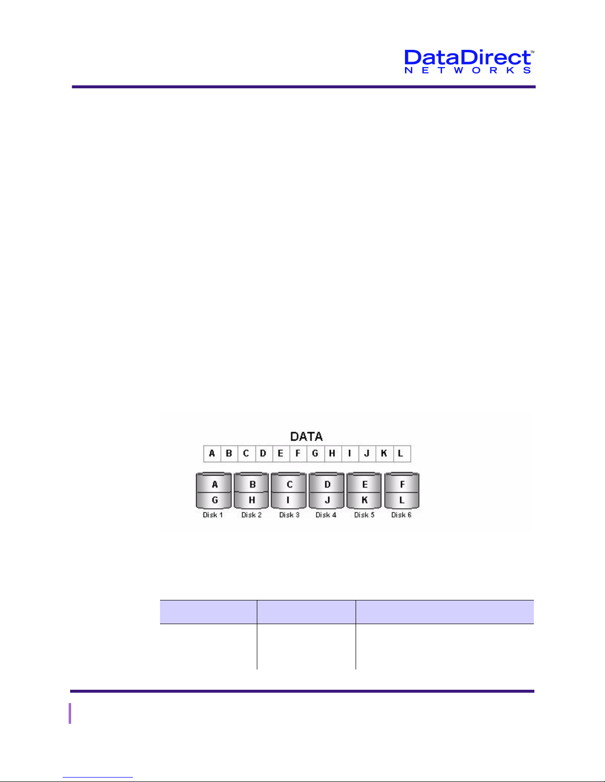
RAID Level 0
RAID level 0 is best suited to applications that require high I/O speed and no data
redundancy. In RAID level 0, the data is broken down into segments and written
simultaneously across multiple disks (Figure 2-2). No parity or check-disk information is
saved. Data is read simultaneously from the multiple disks. This configuration results in
maximum possible I/O speed, but it offers no data protection.
Figure 2-2. RAID Level 0 File System
The characteristics of RAID level 0 are summarized in Table 2 -2.
Table 2-2. Characteristics of RAID Level 0
Advantages Disadvantages Uses
High read/write rate. No data protection. Applications requiring maximum possible
I/O speed and where data integrity is not
important.
14 EF2915 Series User Guide
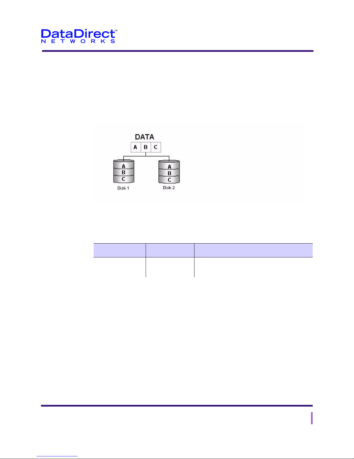
RAID Level 1
Chapter 2: The EF2915 Series Storage System
Introduction to RAID Technology
RAID level 1 is best suited for use by database and file servers that require high
availability.
RAID level 1 uses a technique called mirroring to achieve high data availability. The data
is divided into blocks, with the same block being written simultaneously to a pair of disks,
and read from one of the two mirrored disks (Figure 2-3). The drawback of this technique
is that half the available disk capacity is used for data protection.
Figure 2-3. RAID Level 1 File System
The characteristics of RAID level 1 are summarized in Table 2 -3.
Table 2-3. Characteristics of RAID Level 1
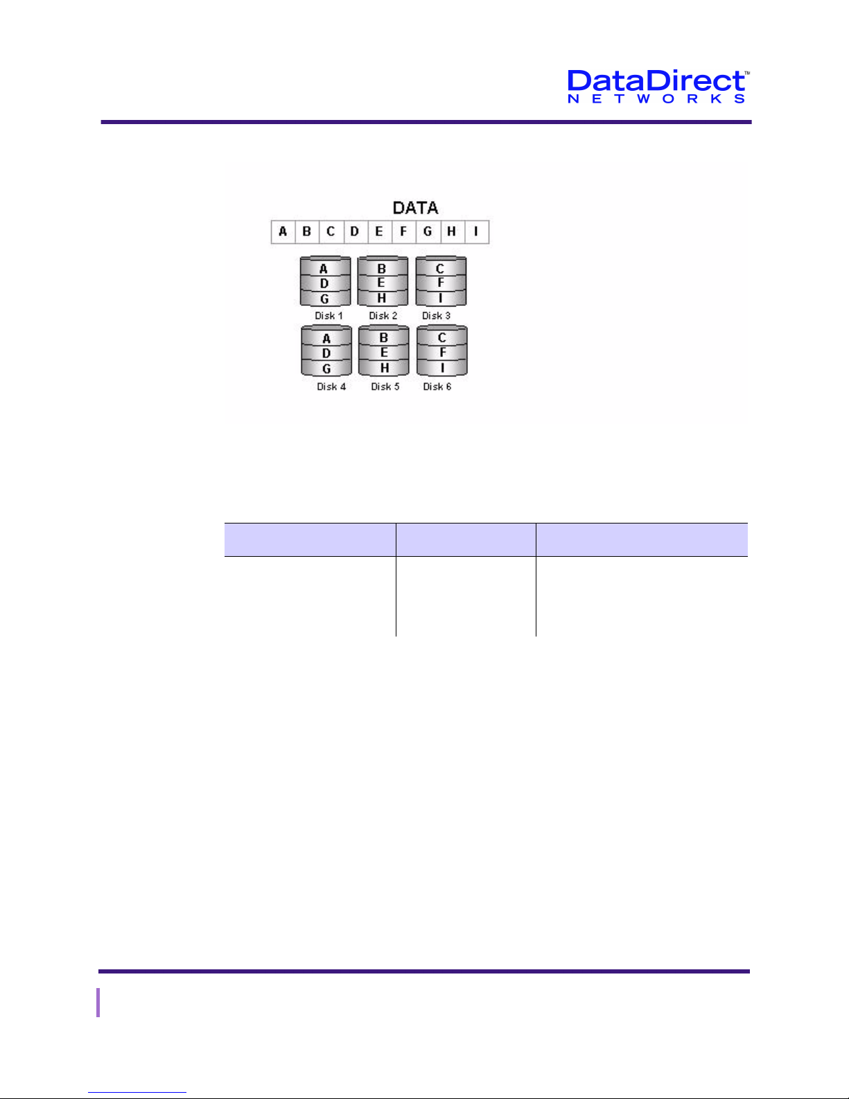
RAID Level 1+0
RAID level 1+0 (like level 5) is best suited to read-intensive, random operations and
online transaction processing (OLTP), which involves frequent file access.
RAID level 1+0 uses a method in which the data is mirrored onto a group of disk drives
(Figure 2-4 on page 16). It provides the highest I/O performance and the highest data
redundancy. The drawback of this technique is that utilization of disk capacity is only
50%.
Advantage Disadvantage Uses
Ensures data
availability.
Reduces disk
capacity.
Database or file-server applications where data
availability is the first priority.
EF2915 Series User Guide 15
Chapter 2: The EF2915 Series Storage System
Introduction to RAID Technology
Figure 2-4. RAID 1+0
The characteristics of RAID level 1+0 are summarized in Table 2 -4 .
RAID Level 3
Table 2-4. Characteristics of RAID Level 1+0
Advantages Disadvantages Uses
High I/O for random read/
write, double redundancy,
hot spare configured.
Utilization of disk
capacity on a RAID
set reduced by half.
Applications for read-intensive,
random operations; on-line
transaction processing with
frequent file access.
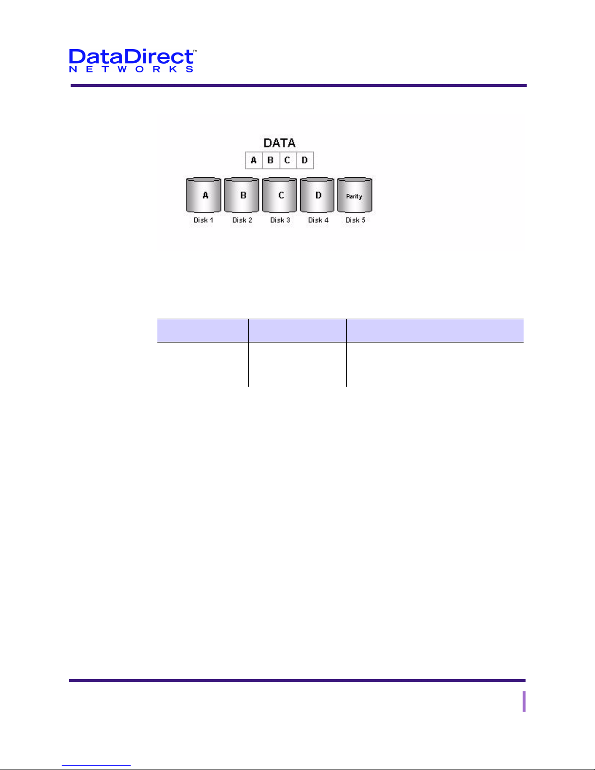
RAID level 3 is best suited to applications that require the reading and writing of large
blocks of data.
In RAID level 3, the data is broken down into segments that are written simultaneously to
different disks. A separate disk is used to store parity information for the data written on
the other disks (Figure 2-5). Should data be lost because of disk failure, it can be
reconstructed from data on the remaining disks. This arrangement provides high I/O
throughput, high data transfer speed, and data protection. But it is inefficient in the reading
and writing of small blocks of data.
16 EF2915 Series User Guide
Chapter 2: The EF2915 Series Storage System
Introduction to RAID Technology
Figure 2-5. RAID Level 3 File System
The characteristics of RAID level 3 are summarized in Table 2 -5.
Table 2-5. Characteristics of RAID Level 3
Advantages Disadvantages Uses
RAID Level 5
Ensures I/O
throughput and data
transfer speed.
Inefficient for small
blocks of data.
Applications requiring reading and writing
large blocks of data.
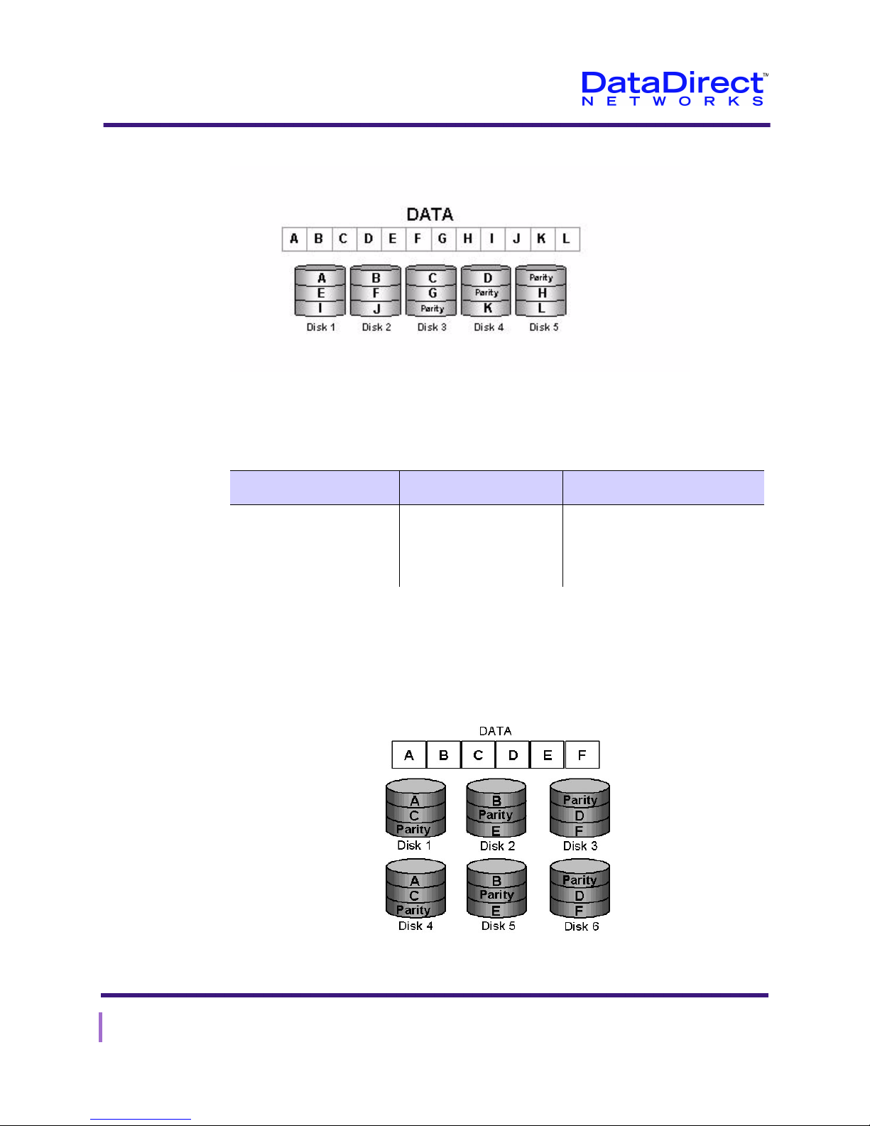
RAID level 5 is best suited to read-intensive, random operations and online transaction
processing (OLTP), which involves frequent file access.
RAID level 5 uses a method in which the data is divided into stripes and the data and
parity information is written simultaneously to the disks in an alternating fashion
(Figure 2-6). This results in increased data availability, more system up-time in the event
of a disk failure, and better read concurrence when reading small blocks of data. The
drawback of this technique is decreased system write performance and increased overhead
in writing small blocks of data.
EF2915 Series User Guide 17
Chapter 2: The EF2915 Series Storage System
Introduction to RAID Technology
Figure 2-6. RAID Level 5
The characteristics of RAID level 5 are summarized in Table 2 -6.
Table 2-6. Characteristics of RAID Level 5
Advantages Disadvantages Uses
RAID Level 50
Enhances data availability,
system reliability, and
handling of small data
blocks.
Decreases overall system
performance because of
increased overhead.
Applications for read-intensive,
random operations; on-line
transaction processing with
frequent file access.
RAID 50 should have been called "RAID 03" because it was implemented as a striped
(RAID level 0) array whose segments were RAID 3 arrays (during mid-90s)
Figure 2-7. RAID 50
18 EF2915 Series User Guide
Chapter 2: The EF2915 Series Storage System
Introduction to RAID Technology
The characteristics of RAID level 50 are summarized in Ta bl e 2-7.
Table 2-7. Characteristics of RAID Level 50
Advantages Disadvantages Uses
RAID Level 6
RAID 50 is more fault
tolerant than RAID 5 but
has twice the parity
overhead
High data transfer rates are
achieved thanks to its
RAID 5 array segments
High I/O rates for small
requests are achieved
thanks to its RAID 0
striping
Very expensive to
implement
All disk spindles must
be synchronized,
which limits the
choice of drives
Failure of two drives
in one of the RAID 5
segments renders the
whole array unusable
Maybe a good solution for sites
which would have otherwise gone
with RAID 5 but need some
additional performance boost
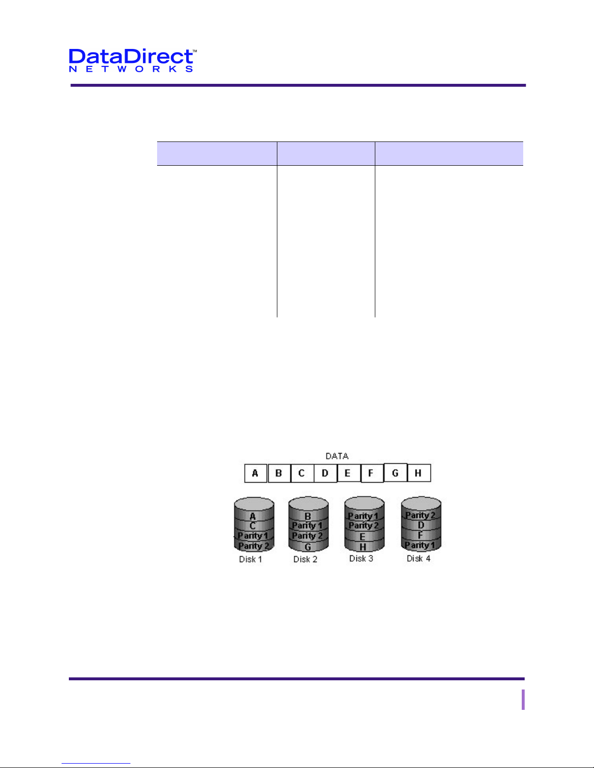
RAID 6 is essentially an extension of RAID level 5 which allows for additional fault
tolerance by using a second independent distributed parity scheme (dual parity)
Data is striped on a block level across a set of drives, just like in RAID 5, and a second set
of parity is calculated and written across all the drives; RAID 6 provides for an extremely
high data fault tolerance and can sustain multiple simultaneous drive failures
Figure 2-8. RAID 6
EF2915 Series User Guide 19

Chapter 2: The EF2915 Series Storage System
Introduction to RAID Technology
The characteristics of RAID level 6 are summarized in Table 2 -8.
Table 2-8. Characteristics of RAID Level 6
Advantages Disadvantages Uses
Perfect solution for mission
critical applications
More complex
controller design
Controller overhead
to compute parity
addresses is
extremely high
Requires N+2 drives
to implement because
of dual parity scheme
File and Application servers
Database servers
Web and E-mail servers
Intranet servers
Excellent fault-tolerance with the
lowest overhead
20 EF2915 Series User Guide

Chapter 2: The EF2915 Series Storage System
Key Terms Used in This Guide
RAID technology includes unique concepts and terminology. Here is a brief list of key
terms that appear in this User Guide. See Chapter 7, “Glossary” for definitions of more
general terms.
back end
Encompasses the path between the RAID SP120/SP125 storage processors and the
hard disks.
chunks
The units of data that are written onto drives in a RAID set. Large blocks of data are
broken into chunks to optimize I/O performance.
chunk size
The size of each data chunk. This parameter is a configured value that becomes fixed
when the system initializes.
data availability
The level of fault tolerance within the RAID system. Availability increases as a
function of the number of component failures that can occur without affecting overall
system performance.
Key Terms Used in This Guide
data integrity
The operability of the RAID system and its ability to withstand failure.
front end
The path between the host interface and the RAID SP120/SP125 storage processor.
dual porting
An interface method that enables multiple hosts to access the same RAID set through
the same RAID hardware.
host portability
The ability to move a RAID unit between different operating systems and host
systems.
lookahead
The threshold for determining how many sequential request should be received before
the read head is enabled. See readahead.
middleware
The DataDirect Networks middleware is a daemon program that runs on the manage-
ment console to which the RAIDs are connected.
EF2915 Series User Guide 21

Chapter 2: The EF2915 Series Storage System
Key Terms Used in This Guide
parity or checksum
Information stored on a disk in RAID levels 3 and 5 and used as a backup in case of
disk failure. The parity information, along with the data on the remaining drives,
provides complete information and enables the system to reconstruct the data of the
failed drive.
readahead
An automatic function the system performs when continuous sequential read requests
are received. With readahead, the system automatically reads into the data blocks from
disks before a request is received from the host.
request rate
The frequency of I/O requests.
striping
A process that binds a group of disks to form one logical unit. Striping often increases
performance over that of one disk.
transfer rate
The speed of data transmissions in millions of bits per second (Mbps).
22 EF2915 Series User Guide

EF2915 Series Specifications
Lists of the physical, electrical, environmental, interface, SP120/SP125 storage processor,
and disk drive specifications for the
Table 2-9. EF2915 Series Specifications
Dimensions
Rack Mount Unit 5.20” H x 17.58” W x 18.70” D
3U EIA high (19” rack mount)
Electrical
Input Voltage 90-260VAC
Input Frequency 47-63 Hz, auto-ranging, PFC
Power Supply Rating Dual 460 Watt, redundant
Chapter 2: The EF2915 Series Storage System
EF2915 Series Specifications
EF2915 Series are shown in Ta bl e 2 -9 .
Mean Time Between Failure
(MTBF)
Environmental
Operating Temperature 10 to 40 degrees Celsius
Relative Humidity 20% to 80%
Certification FCC/CISPR 22 Class A, BSMI, UL/CUL, CE
Interfaces
Host Interface Four 4Gb Fibre Channel interfaces, or four 2Gb iSCSI
Storage Controller
Cache Memory Up to 2GB per storage controller (4GB total)
Parity Four embedded hardware parity accelerators to boost
Number of LUNs 512 (per controller)
33,730 hours
50 to 104 degrees Fahrenheit
interfaces, 400Mb/s (1600 Mb/s total).
Single or Dual
RAID performance.
EF2915 Series User Guide 23
 Loading...