

Data Controls GS-2328KX Installation And Getting Started Manual

Publication date: Feb, 2012
Revision A1
1
GS-2328KX
Gigabit Managed Switch
Installation and Getting Started Guide

Publication date: Feb., 2012
Revision A1
i
INSTALLATION and GETTING STARTE GUIDE
GS-2328KX
Series
Switch
GS-2328KX Series Gigabit Managed Switch
Installation and Getting Started Guide
© 2012, Datacontrols,Inc. All rights reserved. All brand and product names are
trademarks or registered trademarks of their respective companies
Publication date: Feb., 2012
Revision A1
ii
ABOUT THIS GUIDE
PURPOSE
This guide gives specific information on how to operate and
use the management functions of the switch.
AUDIENCE The guide is intended for use by network administrators who
are responsible for operating and maintaining network
equipment; consequently, it assumes a basic working
knowledge of general switch functions, the Internet Protocol
(IP), and Simple Network Man a geme n t P r ot oco l ( SN MP ).
CONVENTIONS
The following conventions are use d throughout this guide to
show information:
WARRANTY
See the Customer Support/ Warranty booklet included with
the product.
A copy of the specific warranty terms applicable to your
Datacontrols products and replacement parts can be obtained
from your Datacontrols Sales and Service Office pr authorized
dealer.
NOTE: Emphasizes important information or calls your
attention to related features or instructions.
W
ARNING
:
Alerts you to a potential hazard t hat could cause
personal injury.
C
AUTION
:
Alerts you to a pote ntial hazard that could ca use loss
of data, or damage the system or equipment.

Publication date: Feb, 2012
Revision A1
iii
COMPLIANCES AND
SAFETY STATEMENTS
FCC-CLASS A
This equipment has been tested and found to comply with the
limits for a Class A computing device pursuant to Subpart J of
part 15 of FCC Rules, which are designed to provide reasonable
protection against such interference when operated in a
commercial environment.
This equipment generates, uses, and can radiate radio
frequency energy and, if not installed and used in accordan ce
with the instruction manual, may cause harmful interference to
radio communications. Operation of this equipment in a
residential area is likely to cause harmful interference in which
case the user will be required to correct the interference at his
own expense.
You are cautioned that changes or modifications not expressly
approved by the party responsible for compliance could void
your authority to operate the equipment.
You may use unshielded twisted-pair (UTP) for RJ-45
connections - Category 3 or better for 10 Mbps connections,
Category 5 or better for 100 Mbps connections, Cate gory 5, 5e,
or 6 for 1000 Mbps connections. For fiber optic connectio ns, you
may use 50/125 or 62.5/125 micron multimode fiber or 9/125
micron single-mode fiber.
CE MARK
DECLARATION
OF CONFORMANCE
FOR EMI AND
SAFETY (EEC)
This equipment has been tested and found to comply with the
protection requirements of European Emission Standard
EN55022/EN61000-3 and the Generic European Immunity
Standard EN55024.
Publication date: Feb, 2012
Revision A1
iv
EMC:
EN55022(2006)+A1:2007/CISPR
22:2006+A1:2006
Class A
4K V CD, 8KV, AD
IEC61000-4-2 (2001) 3V/m
IEC61000-4-3( 2002) 1KV – (power line), 0.5KV – (signal line)
IEC61000-4-4(2004) Line to Line: 1KV, Line to Earth: 2KV
IEC61000-4-5 (2001) 130dBuV(3V) Level 2
IEC61000-4-6 (2003) 1A/m
IEC61000-4-8 (2001) Voltage dips:
>95%, 0.5period, 30%, 25periods
IEC61000-4-11(2001) Voltage interruptions:
>95%, 250periods
C
AUTION
:
Circuit devices are sensitive to static electricity, which
can damage their delicate electronics. Dry weather conditions
or walking across a carpeted floor may cause you to acquire a
static electrical charge.
To protect your device, always:
• Touch the metal chassis of your computer to ground the static
electrical charge before you pick up the circuit device.
• Pick up the device by holding it on the left and right edges only .
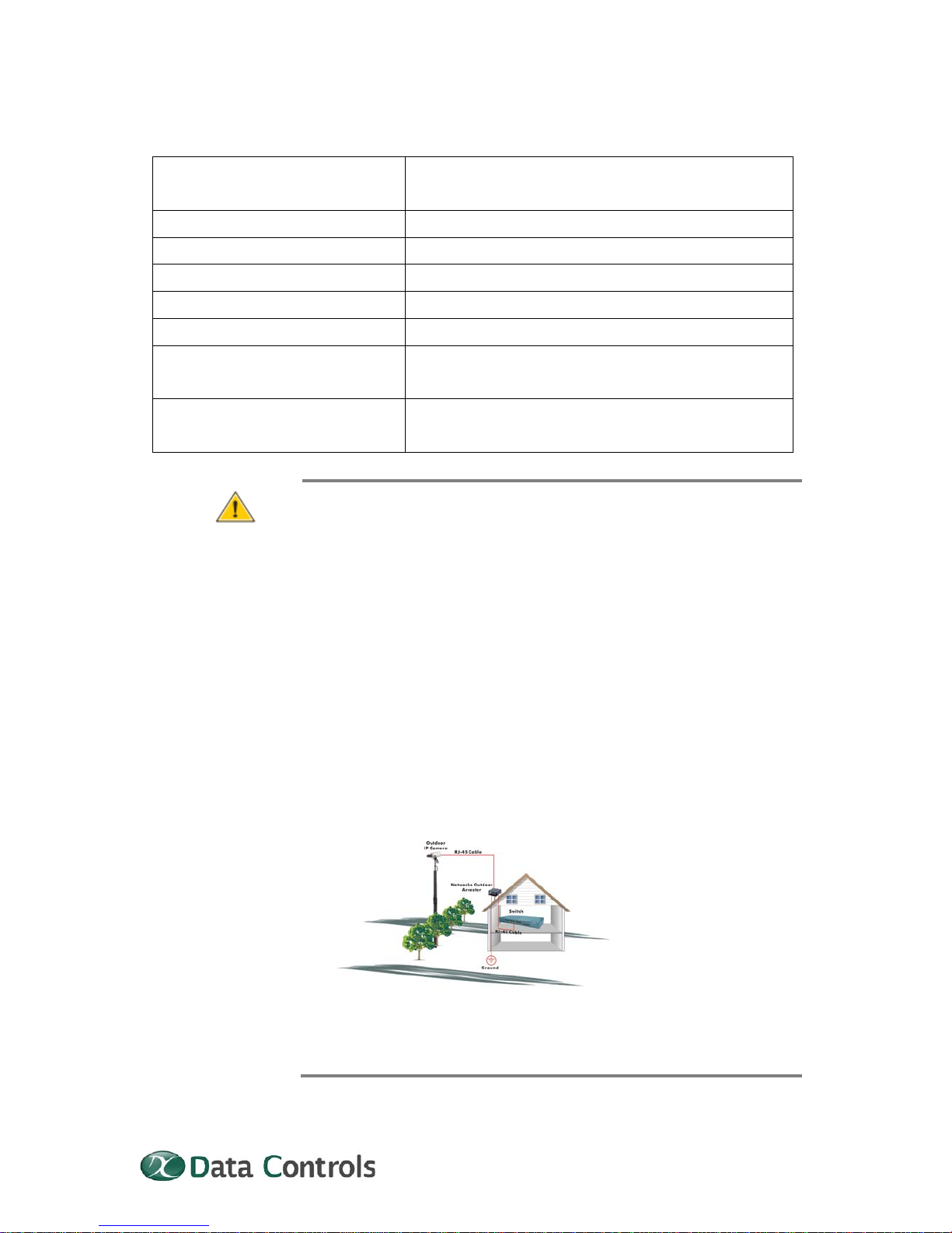
• If you need using outdoor device connect to this device with
cable then you need to addition an arrester on the cable
between outdoor device and this device.
Fig. Addition an arrester between outdoor device and this switch
Publication date: Feb., 2012
Revision A1
5
NOTE: The switch is indoor device; if it will be used in outdoor
environment or connects with some outdoor device, then it must
use a lightning arrester to protect the switch
W
ARNING
:
z Self-demolition on Product is strictly proh ibited. Damage
caused by self-demolition will be charged for repairing fees.
z Do not place product at outdoor or sandstorm.
z Before installation, please make sure input power supply and
product specifications are compatible to each other.
z To reduce the risk of electric shock. Disconnect all AC or DC
power cord and RPS cables to completely remove power
from the unit.
z Before importing / exporting configuration please make sure
the firmware version is always the same.
z After firmware upgrade, the switch will remove the
configuration automatically to latest firmware version.
RELATED
PUBLICATIONS
The following publication gives specific information on how to
operate and use the management functions of the switch:
The User’s Manual
REVISION
HISTORY
This section summarizes the changes in each revis ion of this
guide.
Release Date Revision
1.14 02/14/2012 A1

Publication date: Feb., 2012
Revision A1
vi
Contents
ABOUT THIS GUIDE ..................................................................................................................................... ii
COMPLIANCES AND SAFETY STATEMENTS ................................................................................... iii
INTRODUCTION ............................................................................................................................................. 1
OVERVIEW ................................................................................................................................................... 1
DESCRIPTION OF HARDWARE .............................................................................................................. 4
NETWORK PLANNING ................................................................................................................................ 7
INTRODUCTION TO SWITCHING .................................................................................................... 7
APPLICATION EXAMPLES .................................................................................................................... 7
INSTALLING THE SWITCH ..................................................................................................................... 10
SELECTING A SITE ................................................................................................................................ 10
ETHERNET CABLING ............................................................................................................................. 10
EQUIPMENT CHECKLIST ..................................................................................................................... 11
PACKAGE CONTENTS ............................................................................................................................ 11
MOUNTING ................................................................................................................................................. 11
INSTALLING AN OPTIONAL SFP TRANSCEIVER .................................................................. 13
CONNECTING TO A POWER SOURCE .......................................................................................... 15
CONNECTING TO THE CONSOLE PORT ...................................................................................... 15
Operation of Web-based Management .......................................................................................... 18
MAKING NETWORK CONNECTIONS ................................................................................................. 21
CONNECTING NETWORK DEVICES .............................................................................................. 21
TWISTED-PAIR DEVICES ................................................................................................................... 21
FIBER OPTIC SFP DEVICES .............................................................................................................. 22
CABLE LABELING AND CONNECTION RECORDS .................................................................... 25
TROUBLESHOOTING ................................................................................................................................. 26
Basic Troubleshooting Tips .............................................................................................................. 26
POWER AND COOLING PROBLEMS ................................................................................................... 28
Installation ................................................................................................................................................ 28

Publication date: Feb., 2012
Revision A1
vii
IN-BAND ACCESS ................................................................................................................................... 28
CABLES ............................................................................................................................................................. 29
TWISTED-PAIR CABLE AND PIN ASSIGNMENTS ................................................................. 29
STRAIGHT- THROUGH WIRING ..................................................................................................... 30
1000BASE-T PIN ASSIGNMENTS .................................................................................................. 31
CABLE TESTING FOR EXISTING CATEGORY 5 CABLE ....................................................... 31
FIBER STANDARDS ............................................................................................................................... 32
SPECIFICATIONS ........................................................................................................................................ 33
PHYSICAL CHARACTERISTICS ....................................................................................................... 33
SWITCH FEATURES ............................................................................................................................... 34
MANAGEMENT FEATURES .................................................................................................................. 34
STANDARDS .............................................................................................................................................. 34
COMPLIANCES ......................................................................................................................................... 35
COMPLIANCES .............................................................................................................................................. 36

Publication date: Feb., 2012
Revision A1
1
INTRODUCTION
OVERVIEW
The GS-2328KX Series 28-Ports Switch, Datacontrols network
next generation solutions, is a portfolio of affordable managed
switches that provides a reliable infrastructure for your
business network. These switches deliver more intelligent
features you need to improve the availability of your critical
business applications, protect your sensitive information, and
optimize your network bandwidth to deliver information and
applications more effectively. Easy to set up and use, it
provides the ideal combination of affordability and capabilities
for entry level Networking includes Small Business or
enterprise application and helps you create a more efficient,
better-connected workforce.
The GS-2328KX Series 28-Ports Switch is broad portfolio of
easy-implement managed Ethernet switches. Models include
with 28 ports of Gigabit Ethernet connectivity, providing ideal
flexibility to design suitable network infrastructure for business
requirement. However, unlike other entry-level switching
solutions that provide advance managed network capabilities
only in the costliest models, all the Series Switches support the
advanced security management capabilities and network
features to support includes data, voice, security, and wireless
technologies. Besides, these switches are easy to deploy and
configure, providing stable and quality performance network
services your business needs.
Publication date: Feb., 2012
Revision A1
2
Front of the Switches
Back of the Switches
GS-2328KX
GS-2328KX

Publication date: Feb., 2012
Revision A1
3
SWITCH
ARCHITECTURE
The switch performs a wire-speed, non-blocking switching fabric.
This allows wire-speed transport of multiple packets at low
latency on all ports simultaneously. The switch also features
full-duplex capability on all ports, which effectively doubles the
bandwidth of each connection.
This switch uses store-and-forward technology to ensure
maximum data integrity. With this technolo gy, the entire packet
must be received into a buffer and checked for validity before
being forwarded. This prevents errors from being propagated
throughout the network.
NETWORK
MANAGEMENT
OPTIONS
The switch can also be managed over the network with a web
browser or Telnet application. The switch includes a built-in
network management agent that allows it to be managed
in-band using SNMP or RMON (Groups 1, 2, 3, 9) protocols. It
also has an RS-232 console port connector on the front panel for
out-of-band management. A PC may be connected to this port
for configuration and monitoring out-of-band via a null- modem
serial cable. (See Appendix B for wiring options.)
NOTE: For a detailed description of the management features,
refer to the User’s manual
.

Publication date: Feb., 2012
Revision A1
4
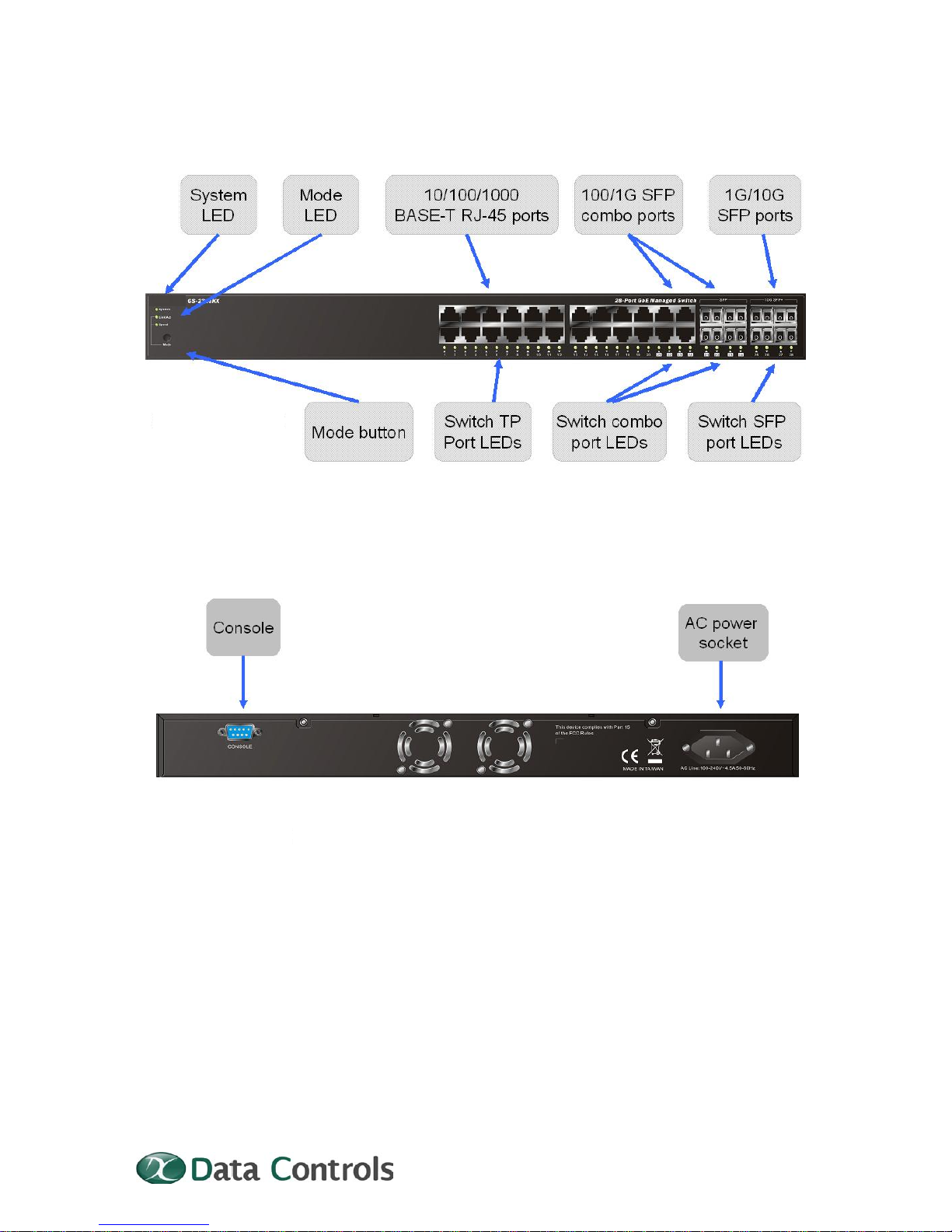
DESCRIPTION OF
HARDWARE
1000BASE-T
PORTS
The switch contains 24 1000BASE-T RJ-45 ports. All RJ-45 ports
support automatic MDI/MDI-X operation, auto-negotiation and
IEEE 802.3x auto-negotiation of flow control, so the optimum
data rate and transmission can be selected automatically.
SFP
TRANSCEIVER
SLOTS
GS-2328KX supports the Small Form Factor Pluggable (SFP)
transceiver slots are shared with RJ-45 port 21 to 24. In the
default configuration, if an SFP transceiver (purchased
separately) is installed in a slot and has a valid link on the port,
the associated RJ-45 port is disabled.
The following table shows a list of transceiver type s whic h have
been tested with the switch. For an updated list of vendors
supplying these transceivers, contact your local dealer. For
information on the recommended standards for fiber optic
cabling, see “1000 Mbps Gigabit Ethernet Co llision Domain” on
page 28.
Table 1: Supported SFP Transceivers
Media Standard
Fiber Diameter
(microns)
Wavelength (nm)
Maximum Distance*
1000BASE-SX 50/125
62.5/125
850
850
550 m
275 m
1000BASE-LX/
LHX/ XD/ZX
9/125
9/125
1310
1550
10,30 km
30,50 km
1000BASE-LX
Single Fiber
9/125 TX-1310/RX-1550
Tx-1550/RX-1310
10,20 km
10,20 km
1000BASE-T N/A N/A 100 m
100-FX 62.5/125
9/125
1310
1310
2 km
20,40,60 km
NOTE: * Maximum distance may vary for different SFP vendors

Publication date: Feb., 2012
Revision A1
5
PORT AND
SYSTEM STATUS
LEDS
The GS-2328KX Series switch includes a display panel for
system and port indications that simplify installation and
network troubleshooting. The LEDs, which are located on left
hand side of the front panel for easy viewing. Details are shown
below and described in the following tables.
Table 2: Port Status LEDs
LED Condition Status
TP (Link/ACT) Green/Blink
Lit Green when TP link good
Blinks when any traffic is present
TP SPEED Green/Yellow/Off
Lit Green when TP link on 1000Mbps
Yellow when TP link on 100Mbps
Off when TP link on 10Mbps
SFP (Link/ACT) Green/Blink
Lit Green when SFP link good
Blinks when any traffic is present
SFP SPEED Blue/Green
Lit Blue when SFP link on 10Gbps.
Green when SFP link on 1000Mbps
Table 3: System Status LED
SYSTEM LED Condition Status
System
Green
OFF
Lit when power is coming up
POWER SUPPLY
SOCKET
There are a power sockets on the rear panel of the switch. For
normal power supply, the GS-2328KX-Port Series Switch has
standard power socket for AC power cord.
Figure 3: Power Supply Socket
AC Power socket
MODE STATUS
LEDS
The GS-2328KX Series switch provides a mode switch
function. There are two mode for all LED of each port, which

Publication date: Feb., 2012
Revision A1
6
can switch between Link/ACT mode and SPEED mode by
pressing MODE button. When the switch is on Link/ACT mode,
the LED of each port indicates the link or act status. The LED of
each port shows the link speed status of the port using
different colors when the switch is on SPEED mode.
Table 4: Mode Status LED
LED Condition Status
Link/ACT
Green
OFF
Lit Green shows all LED of each port are in
Link/ACT mode. Each LED of the port lit
Green when port link is good, and Blinks
when any traffic is present.
SPEED
Blue
Green
Yellow
OFF
Lit Green shows all LED of each port are in
SPEED mode. Each LED of the port lit Blue
when the link on 10Gbps.
Green when the link on 1000Mbps
Yellow when the link on 100Mbps
Off when the link on 10Mbps

Publication date: Feb., 2012
Revision A1
7
NETWORK PLANNING
INTRODUCTION
TO SWITCHING
A network switch allows simultaneous transmission of mult iple
packets, and it can partition a network more efficiently than
bridges or routers. Therefore the switch has been recognized as
one of the most important devices for today’s networking
technology.
When performance bottlenecks are caused by congestion at the
network access point such as file server, the device can be
connected directly to a switched port. And, by using full-duplex
mode, the bandwidth of the dedicated segment can be doubled
to maximize throughput.
When networks are based on repeater (hub) technology, the
distance between end stations is limited by a maximum hop
count. However, a switch can subdividing the network into
smaller and more manageable segments, and linking them to
the larger network than it turns the hop count back to zero and
removes the limitation.
A switch can be easily configured in any Ethernet, Fast Ethernet,
or Gigabit Ethernet network to significantly increase bandwidth
while using conventional cabling and network cards.
APPLICATION
EXAMPLES
The GS-2328KX-Port Series Switch implements 24 Gigabit
Ethernet TP ports with auto MDIX and 4 slots for the removable
SFP module (GS-2328KX) which supports comprehensive types
of fiber connection, such as LC and BiDi-LC modules. It is not
only designed to segment your network, but also to provide a
wide range of options in setting up network connections. Some
typical applications are described below.
The switch is suitable for the following applications.
Remote site application is used in Enterprise or SMB
Peer-to-peer application is used in two remote offices
Office network
High Performance Re qu ire me n t en v iro n m ent
Advance Security for network safety application
Suitable for data/ voice and video conference application
 Loading...