

DATACOM TEXTRON LANcat Series, LANcat TwoWay, LANcat OneWay User Manual

Artisan Technology Group is your source for quality
new and certied-used/pre-owned equipment
• FAST SHIPPING AND
DELIVERY
• TENS OF THOUSANDS OF
IN-STOCK ITEMS
• EQUIPMENT DEMOS
• HUNDREDS OF
MANUFACTURERS
SUPPORTED
• LEASING/MONTHLY
RENTALS
• ITAR CERTIFIED
SECURE ASSET SOLUTIONS
SERVICE CENTER REPAIRS
Experienced engineers and technicians on staff
at our full-service, in-house repair center
Instra
Remotely inspect equipment before purchasing with
our interactive website at www.instraview.com
Contact us: (888) 88-SOURCE | sales@artisantg.com | www.artisantg.com
SM
REMOTE INSPECTION
View
WE BUY USED EQUIPMENT
Sell your excess, underutilized, and idle used equipment
We also offer credit for buy-backs and trade-ins
www.artisantg.com/WeBuyEquipment
LOOKING FOR MORE INFORMATION?
Visit us on the web at www.artisantg.com for more
information on price quotations, drivers, technical
specications, manuals, and documentation

LANcat Series
Cable Testers
User Manual
Artisan Technology Group - Quality Instrumentation ... Guaranteed | (888) 88-SOURCE | www.artisantg.com

Datacom Textron may make improvements or additions to this publication
or their products at any time without notice.
Datacom Textron shall not be liable for technical or editorial errors or omissions
contained herein.
LANcat is a trademark of Datacom Textron.
P/N 13520 Rev. F
© Copyright 1999 by Datacom Textron
11001 31st Place West
Everett, WA 98204
Telephone 425-355-0590
800-468-5557
Fax 425-290-1600
www.datacom.textron.com
Artisan Technology Group - Quality Instrumentation ... Guaranteed | (888) 88-SOURCE | www.artisantg.com

WARRANTY STATEMENT
The LANcat is warranted against defects in materials and
workmanship within a period of two (2) years following the date of
purchase of the tester.
Any instrument claimed to be defective during the warranty
period should be returned to Datacom Textron’s Fac tory Service
Center. Refer to the chapter on Technical Support and Service
for further instructions.
ANY IMPLIED WARRANTIES ARISING OUT OF THE SALE OF
A LANCAT CABLE TESTER, INCLUDING BUT NOT LIMITED
TO IMPLIED WARRANTIES OF MERCHANTABILITY AND
FITNESS FOR A PARTICULAR PURPOSE, ARE LIMITED IN
DURATION TO THE ABOVE STATED TWO (2) YEAR PERIOD.
DATACOM TEXTRON SHALL NOT BE LIABLE FOR LOSS OF
USE OF THE TESTER OR OTHER INCIDENTAL OR
CONSEQUENTIAL DAMAGES, EXPENSES OR ECONOMIC
LOSS.
Some states and countries do not allow limitations on how long
implied warranties last or the exclusions or limitation of inc idental
or consequential damages, so the above limitations or ex clus ions
may not apply to you. This warranty gives you specific legal
rights, and you may also have other rights which var y from state
to state.
Datacom Textron certifies that this instrument was thoroughly
tested and found to meet its published specifications when
shipped from the factory.
Artisan Technology Group - Quality Instrumentation ... Guaranteed | (888) 88-SOURCE | www.artisantg.com

Table of Contents
Table of Contents
1. INTRODUCTION
Overview of Features........................................................................ 1-2
Battery Information............................................................................ 1-9
Display Conventions........................................................................ 1-11
2. GETTING STARTED
Initial Instrument Set Up.................................................................... 2-1
Typical Test Set Up........................................................................... 2-5
Selecting a Cable Test Standard....................................................... 2-9
System Integrity Pre-Test................................................................2-10
3. AUTOTEST
Running Autotest...............................................................................3-2
V i e w i n g Autotest R e s u l t s ............................................................. 3-4
Saving Autotest Results....................................................................3-8
LinkTalk (LANcat TwoWay)......................................................... 3-11
4. QUICK CHECK
Running Quick Check ....................................................................... 4-2
Viewing Quick Check Results ........................................................... 4-4
5. CABLE TEST DESCRIPTIONS
Wire Map........................................................................................... 5-2
NEXT.................................................................................................5-4
Power Sum NEXT............................................................................. 5-9
Cable Grading.................................................................................5-13
Length ............................................................................................. 5-16
Page i
Artisan Technology Group - Quality Instrumentation ... Guaranteed | (888) 88-SOURCE | www.artisantg.com

LANcat User Manual
Delay/Delay Skew...........................................................................5-20
Attenuation......................................................................................5-22
ACR.................................................................................................5-26
Noise...............................................................................................5-28
Pair Reversal Test...........................................................................5-31
Repeatability Test............................................................................ 5-32
Impedance ...................................................................................... 5-33
Resistance (LANcat TwoWay)........................................................ 5-34
Cable Toner..................................................................................... 5-36
6. PRINTING, UPLOADING, VIEWING TEST RESULTS
Connecting To a PC or Printer..........................................................6-1
Printing/Uploading Test Results........................................................ 6-3
Deleting Test Reports ....................................................................... 6-8
Viewing Saved Test Reports............................................................. 6-9
7. TESTING TWISTED PAIR CABLE
Types of Twisted Pair Cable ............................................................. 7-1
Twisted Pair Test Descriptions..........................................................7-2
Testing Tips.....................................................................................7-33
8. SETUP
Changing SetUp Parameters ............................................................ 8-3
9. CALIBRATION AND UPGRADING
NVP Calibration.................................................................................9-1
Remote Unit Calibration....................................................................9-5
Performance Module Calibration....................................................... 9-7
Impedance Calibration ...................................................................... 9-9
Resistance Calibration .................................................................... 9-10
Main Unit Calibration....................................................................... 9-11
Page ii
Artisan Technology Group - Quality Instrumentation ... Guaranteed | (888) 88-SOURCE | www.artisantg.com

Table of Contents
Upgrading the LANcat..................................................................... 9-11
10. ETHERNET TRAFFIC ANALYSIS
Running Traffic Test........................................................................ 10-2
Viewing Traffic Results....................................................................10-3
11. TECHNICAL SUPPORT AND SERVICE
LANcat Self Test ............................................................................. 11-2
APPENDIX A. TEST STANDARDS
Installed Link Test Configuration.......................................................A-1
Channel Testing................................................................................A-2
Basic Link Testing.............................................................................A-4
EIA/TIA TSB-67 - Test Limits............................................................A-6
ISO/IEC - Test Limits ........................................................................A-8
Enhanced Cable Standards – Test Limits.......................................A-10
IEEE Twisted Pair – Test Limits......................................................A-10
Defining Custom Standards ............................................................A-16
APPENDIX B. COMMON CABLE NVP VALUES
APPENDIX C. SPECIFICATIONS
APPENDIX D. CABLE REPLACEMENT PROCEDURE
APPENDIX E. GLOSSARY
Page iii
Artisan Technology Group - Quality Instrumentation ... Guaranteed | (888) 88-SOURCE | www.artisantg.com

LANcat User Manual
Page iv
Artisan Technology Group - Quality Instrumentation ... Guaranteed | (888) 88-SOURCE | www.artisantg.com

Chapter 1 Introduction
1. INTRODUCTION
The LANcat Series are precision instruments for the certification
and troubleshooting of LAN cable installations.
With plug-in Performance Modules, the LANcat Series are capable
of testing a wide variety of cable types including
Category 5/Class D twisted pair, coaxial cable, and fiber optic
cable.
This User Manual covers two LANcat Series model configurations.
All models are fully compliant with the testing requirements of the
TIA/EIA 568A TSB-67 and provide Level II measurement
accuracy when testing Category 5 Basic Links.
LANcat OneWay
. The OneWay System performs one way nearend crosstalk (NEXT) measurements up to 100 MHz. Testing of
NEXT from both ends of the link, as now required by TIA TSB-67
for compliant Category 5 installations, is accomplished by
completing separate tests from each end. The test system includes
a main handheld unit and an Active Remote (also called OneWay
Remote).
LANcat TwoWay
. The TwoWay System performs automatic bidirectional measurements of NEXT up to 100 MHz. The test
system includes two LANcat TwoWay handheld units, each having
a full graphic display and control panel. Either unit may be
operated as a main or a remote unit for testing twisted pair links.
Page 1-1
Artisan Technology Group - Quality Instrumentation ... Guaranteed | (888) 88-SOURCE | www.artisantg.com

LANcat User Manual
Overview of Features
The features and functions of the LANcat include:
TESTING FEATURES
OneWay or TwoWay system testing.
•
Tests UTP, ScTP, coaxial, STP, and fiber optic cable.
•
Certifies twisted pair cable up to EIA/TIA 568A Category 5
•
and ISO/IEC 11801 Class D (100 MHz).
Performs NEXT, Length, Wire Map, Attenuation, Noise,
•
Traffic, Impedance, and Resistance tests
Performs a preprogrammed suite of certification tests when
•
set to Autotest.
Performs enhanced cable tests including Power Sum
•
NEXT, Delay/Delay Skew, and Cable Grading to test
emerging new enhanced data cables.
Cable Toner enables identification of cable at far end.
•
Page 1-2
Artisan Technology Group - Quality Instrumentation ... Guaranteed | (888) 88-SOURCE | www.artisantg.com

Chapter 1 Introduction
PRODUCT FEATURES
Stores up to 500 Autotest results on a OneWay System, or
•
1000 for a TwoWay System.
Graphical user interface on the main and remote units
•
allowing test results to be viewed at both ends.
Backlit LCD display.
•
Easy field updates of hardware and software using
•
plug-in Performance Modules and flash memory.
Operates using either replaceable AA batteries, AC/Mains
•
power, or a rechargeable NiMH battery pack (optional).
Voice communication between main unit and the remote
•
(LANcat TwoWay).
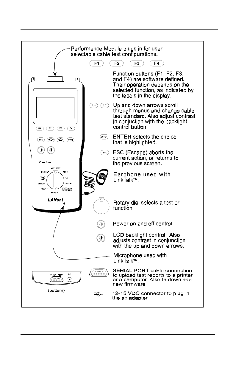
The features of the LANcat, and how they are used, are briefly
described in Figure 1-1.
Page 1-3
Artisan Technology Group - Quality Instrumentation ... Guaranteed | (888) 88-SOURCE | www.artisantg.com
LANcat User Manual
Figure 1-1. LANcat Overview of Features
Page 1-4
Artisan Technology Group - Quality Instrumentation ... Guaranteed | (888) 88-SOURCE | www.artisantg.com

Chapter 1 Introduction
Tests and functions accessible using the rotary dial are described in
Figure 1-2.
AUTOTEST
QUICK
WIRE
MAP
LENGTH
TRAFFIC
Figure 1-2. Function Dial
Dial Position Function
AUTOTEST
Performs a preprogrammed suite of tests, which
are required to certify a cable installation.
PRINT
Print, view, or upload to PC, Autotest and/or
Traffic reports.
CAL
Calibrate cable NVP, Performance Module and
Remote.
SETUP
Changes operation characteristics including
Time/Date.
EXTENDED
FUNCTIONS
REMOTE
Individual cable tests, unit selftest, pair reversal
test, repeatability test and flash memory downlo ad.
Puts LANcat into remote mode, for use in
TwoWay testing
TRAFFIC
LENGTH
Monitors traffic activity on an Ethernet network.
Determines the cable length and up to two
intermediate anomalies.
WIRE MAP
Determines pin-to-pin continu ity, shield continuity
and split pairs.
QUICK
Performs an abbreviated Autotest test sequence as
a fast cable installation check.
REMOTE
PRINT
CAL
SETUP
EXTENDED
FUNCTIONS
Page 1-5
Artisan Technology Group - Quality Instrumentation ... Guaranteed | (888) 88-SOURCE | www.artisantg.com
LANcat User Manual
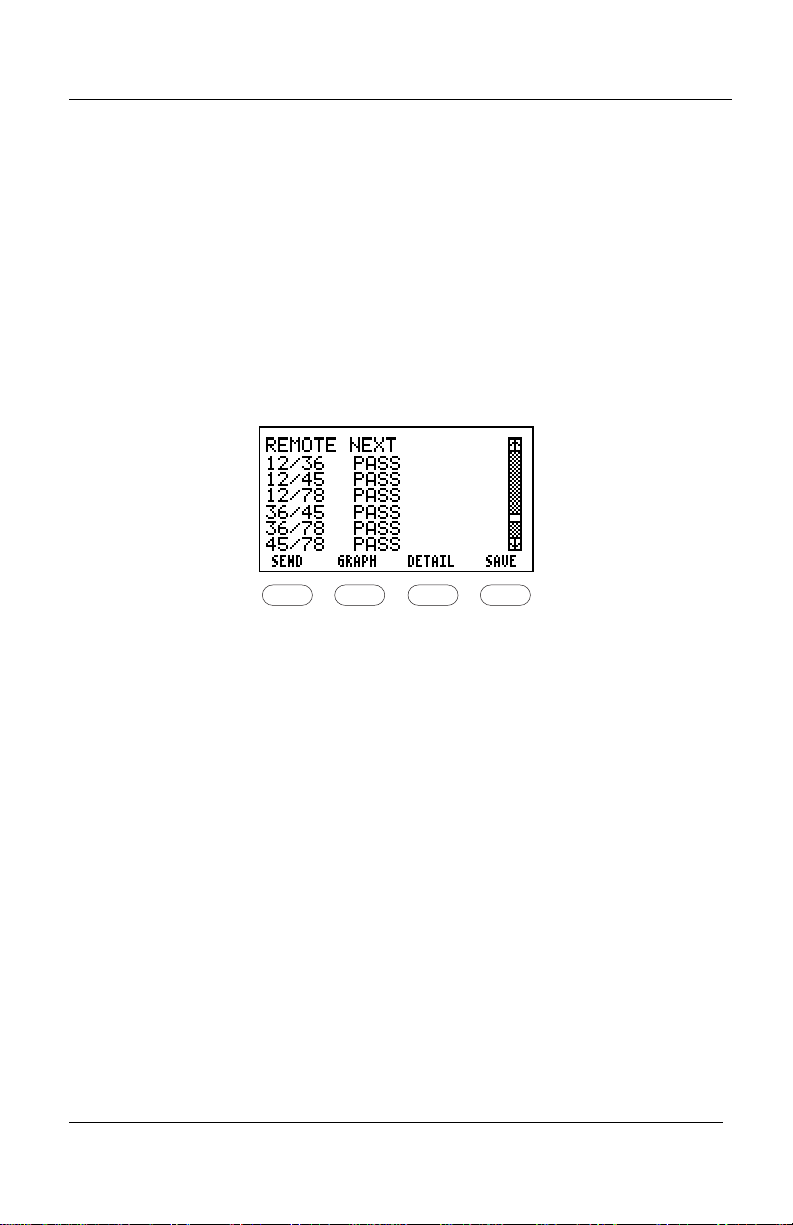
SEND FUNCTION (TWO-WAY SYSTEM)
A Send function is available with the LANcat TwoWay System.
This function allows you to transmit on-screen test results to the
unit at the other end. To use the Send function, simply complete
the test, and when the screen you want to transmit is displayed,
press the corresponding soft function key. For example, in the
figure below, you would press F1 to send the results.
F2
F3
LINKTALK
TM
The LinkTalk
F1
FUNCTION (TWO-WAY SYSTEM)
TM
function is available with the LANcat TwoWay
System. This function allows two way voice communication
between the main unit and the remote. LinkTalk
F4
TM
uses a
microphone embedded in the front of each unit and an earphone
connected to the jack located on each unit’s side. See Chapter 3,
AutoTest, for details.
Page 1-6
Artisan Technology Group - Quality Instrumentation ... Guaranteed | (888) 88-SOURCE | www.artisantg.com
Chapter 1 Introduction
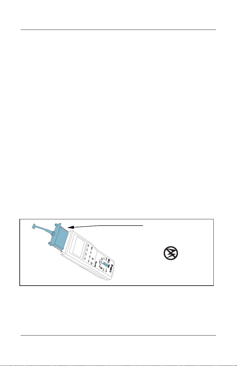
PERFORMANCE MODULE
The LANcat is designed with removable performance modules for
attaching to various cable types and cable connectors. The key to
the LANcat’s high measurement accuracy is using the proper
performance module.
To remove a module, loosen the thumbscrews at either side of the
module until the screws are free of the retainers. Hold the module
on either side and slide it out of the opening (refer to Figure 1-3).
To install a module, slide it into the opening until the screws rest
against the retainers, then hand-tighten the screws until the module
is properly seated.
CAUTION
Avoid damaging the case of the LANcat. Tighten the screws evenly
using finger pressure only. Make sure to either turn both screws
simultaneously or alternately in small increments. The module is
designed to be installed or removed without tools.
Performance Module
Figure 1-3. Module Removal
Page 1-7
Artisan Technology Group - Quality Instrumentation ... Guaranteed | (888) 88-SOURCE | www.artisantg.com
LANcat User Manual
STATIC AWARENESS
The LANcat contains static sensitive electronics inside the main
body. Use appropriate precautions when removing and installing
performance modules.
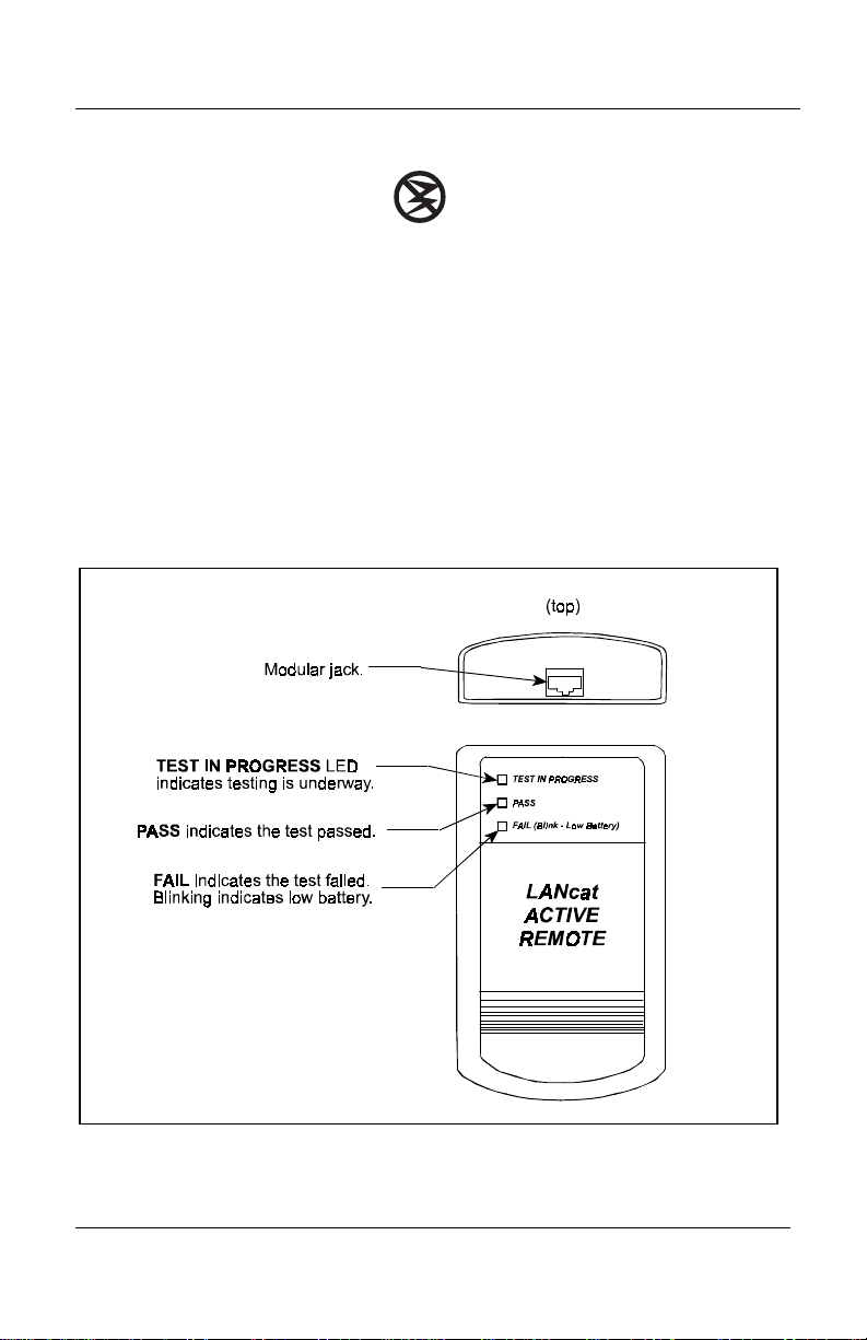
REMOTE UNIT (ONE-WAY SYSTEM)
The Remote Unit is connected at the far end of the cable when
testing twisted pair cable. The Remote Unit (see Figure 1-4) is
used during NEXT, Attenuation and Wire Map tests.
Figure 1-4. Remote Unit
Page 1-8
Artisan Technology Group - Quality Instrumentation ... Guaranteed | (888) 88-SOURCE | www.artisantg.com

Chapter 1 Introduction
Battery Information
The LANcat handheld is shipped with eight AA alkaline batteries.
The Remote Unit is shipped with four AA alkaline batteries.
An optional rechargeable nickel metal hydride (NiMH) battery
pack may be ordered for the LANcat handheld.
A low battery message displays on the LCD screen when it is time
to replace the batteries. When the low battery message appears, you
have 60 seconds to save your test results before power-down
occurs.
MEMORY STORAGE
The LANcat memory is powered from an internal, long-life lithium
cell. Stored test results and set up conditions will therefore be
saved when you replace the AA alkaline batteries or rechargeable
battery pack.
CHARGING MODE
When the AC/mains adapter is used and the LANcat is powered
“off”, the unit goes into a “sleep mode.” With the optional NiMH
rechargeable battery pack installed, the unit goes into a Recharge
mode. A fully discharged battery pack will take approximately 1012 hours to charge to full capacity. To resume testing, press the
Power button.
Page 1-9
Artisan Technology Group - Quality Instrumentation ... Guaranteed | (888) 88-SOURCE | www.artisantg.com

LANcat User Manual
CHANGING THE BATTERIES
To change the batteries in the LANcat:
1. Remove the battery compartment cover, located on the back of
the instrument (refer to Figure1-5).
2. Remove the batteries.
3. Install new batteries paying attention to the polarity markings
on the inside of the battery well.
NOTE
The FAIL LED on the Remote Unit blinks
continuously when the battery is low.
1.
2.
Figure 1-5. Battery Replacement
Page 1-10
Artisan Technology Group - Quality Instrumentation ... Guaranteed | (888) 88-SOURCE | www.artisantg.com
Chapter 1 Introduction
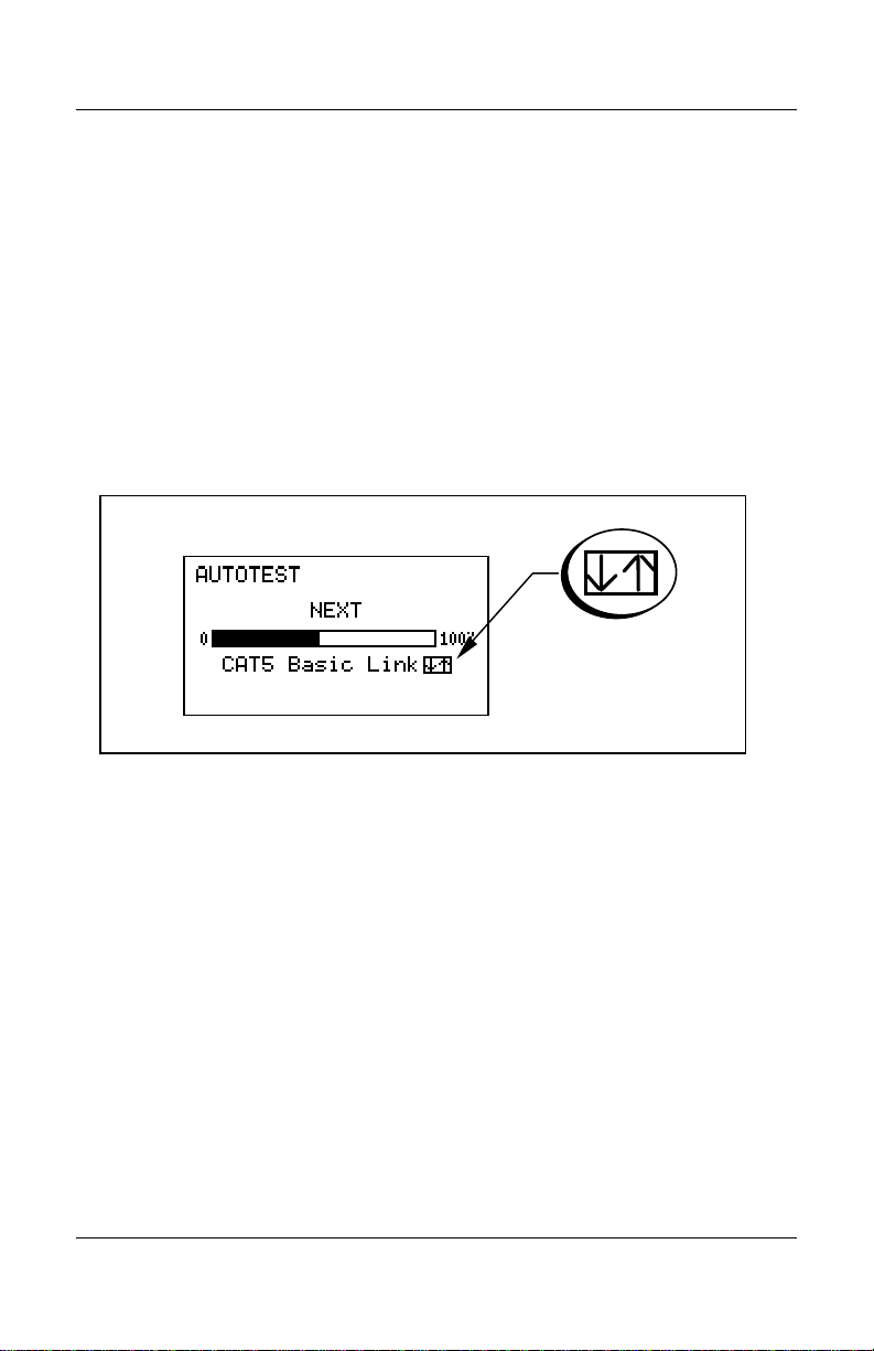
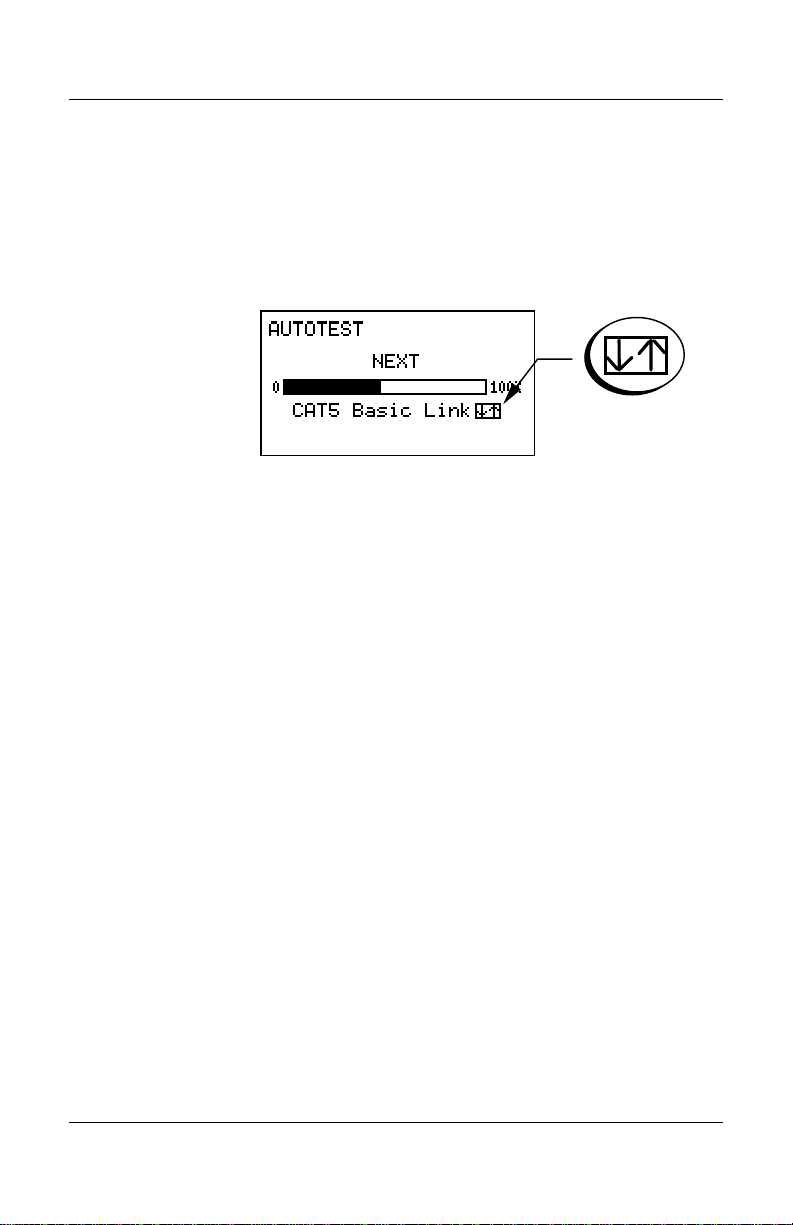
Display Conventions
ARROW KEYS
An up/down arrows symbol
(see detail in Figure 1-6) appears
next to an item on the LCD display to indicate that you can use the
arrow keys to make a different selection. For example, in the
figure below, the arrows appear next to the word “Link” on the
screen.
Figure 1-6. Arrows Symbol
To change a selection:
1. Press the up or down arrow keys to scroll through the available
selections.
2. When the choice you want is highlighted, press SAVE (F4) or
ENTER.
Page 1-11
Artisan Technology Group - Quality Instrumentation ... Guaranteed | (888) 88-SOURCE | www.artisantg.com
LANcat User Manual
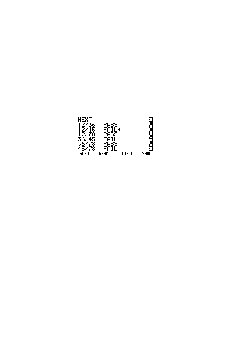
SCROLL BARS
When there are more selections available than can fit on one
LANcat screen, scroll bars will appear. For example, in the figure
below, the scroll bar appears above “Save.”
To use the scroll bar, use the arrow keys to move the scroll-bar
indicator as well as to highlight a new selection.
Figure 1-7 Sample of Scroll Bar
DISPLAY CONTRAST ADJUSTMENT
To adjust the screen contrast, hold down the Backlight button and
press the arrow keys to set the screen contrast for comfortable
viewing.
Page 1-12
Artisan Technology Group - Quality Instrumentation ... Guaranteed | (888) 88-SOURCE | www.artisantg.com

Chapter 2 Getting Started
2. GETTING STARTED
This chapter provides a brief overview to the use of the LANcat for
testing twisted pair cabling. It is intended for those users with prior
cable testing experience who want to get started quickly. It covers
only the basics on initial instrument set up, connections to the
cable and the Autotest function. LANcat users with no prior cable
testing experience are advised to also review Chapter 7, Testing
Twisted Pair Cabling before using this instrument.
Initial Instrument Set Up
Before you first use the LANcat, you should check SETUP, which
controls many basic instrument operations such as power-down
time, backlight “on” time, feet/meters, date, time and serial output
format. Each of these settings, however, has a “default” value
established by the factory. To adjust any of these settings, refer to
Chapter 8, Set Up.
Page 2-1
Artisan Technology Group - Quality Instrumentation ... Guaranteed | (888) 88-SOURCE | www.artisantg.com

LANcat User Manual
SETTING UP THE LANCAT TWO-WAY SYSTEM
To set up the LANcat TwoWay System:
1. Set the remote unit’s dial to REMOTE.
2. Press the remote unit power button on. The display will read
3. Set the main unit’s dial to the test or function you want to
perform.
4. Connect the cable.
5. Press the main unit’s power button on.
SETTING UP THE ONE-WAY SYSTEM
To set up the LANcat OneWay System:
1. Set the LANcat’s dial to the test or function you want to
perform.
2. Connect the cable.
3. Press the LANcat’s power button.
Page 2-2
Artisan Technology Group - Quality Instrumentation ... Guaranteed | (888) 88-SOURCE | www.artisantg.com

Chapter 2 Getting Started
NVP CALIBRATION
In order to make accurate cable length measurements, the correct
cable NVP value must be set in the LANcat. A typical NVP value
will be automatically selected by the LANcat depending on the test
standard that you choose. For greater measurement accuracy,
follow the NVP calibration procedure in Chapter 9, Calibration.
Page 2-3
Artisan Technology Group - Quality Instrumentation ... Guaranteed | (888) 88-SOURCE | www.artisantg.com

LANcat User Manual
Why do I need to set cable NVP?
In order to make accurate cable length
measurements, the correct cable Nominal Vel oci ty
of Propagation (NVP) value must be set in the
LANcat. The NVP is a measure of how fast an
electrical pulse travels down a cable compared to
the speed of light.
NVP is expressed as a percentage and is usually
between 50% and 90%. A default NVP value is
automatically set by the LANcat based upon the
cable test standard selected.
Using the default value, however, may result in
cable length measurement errors of up to 7% due
to the variation in the signal propagation rate from
cable to cable. This potential length error usually
will not impair troubleshooting of a prior working
cable segment unless the length measurement of a
cable is close to the test limit (for example 100
meters on a 10BASE-T segment).
When using the LANcat for cable certification,
determine the true cable NVP and save the value.
This will ensure the most accurate cable length
measurements and will avoid failing cable
segments that are close to the test limit.
Page 2-4
Artisan Technology Group - Quality Instrumentation ... Guaranteed | (888) 88-SOURCE | www.artisantg.com
Chapter 2 Getting Started
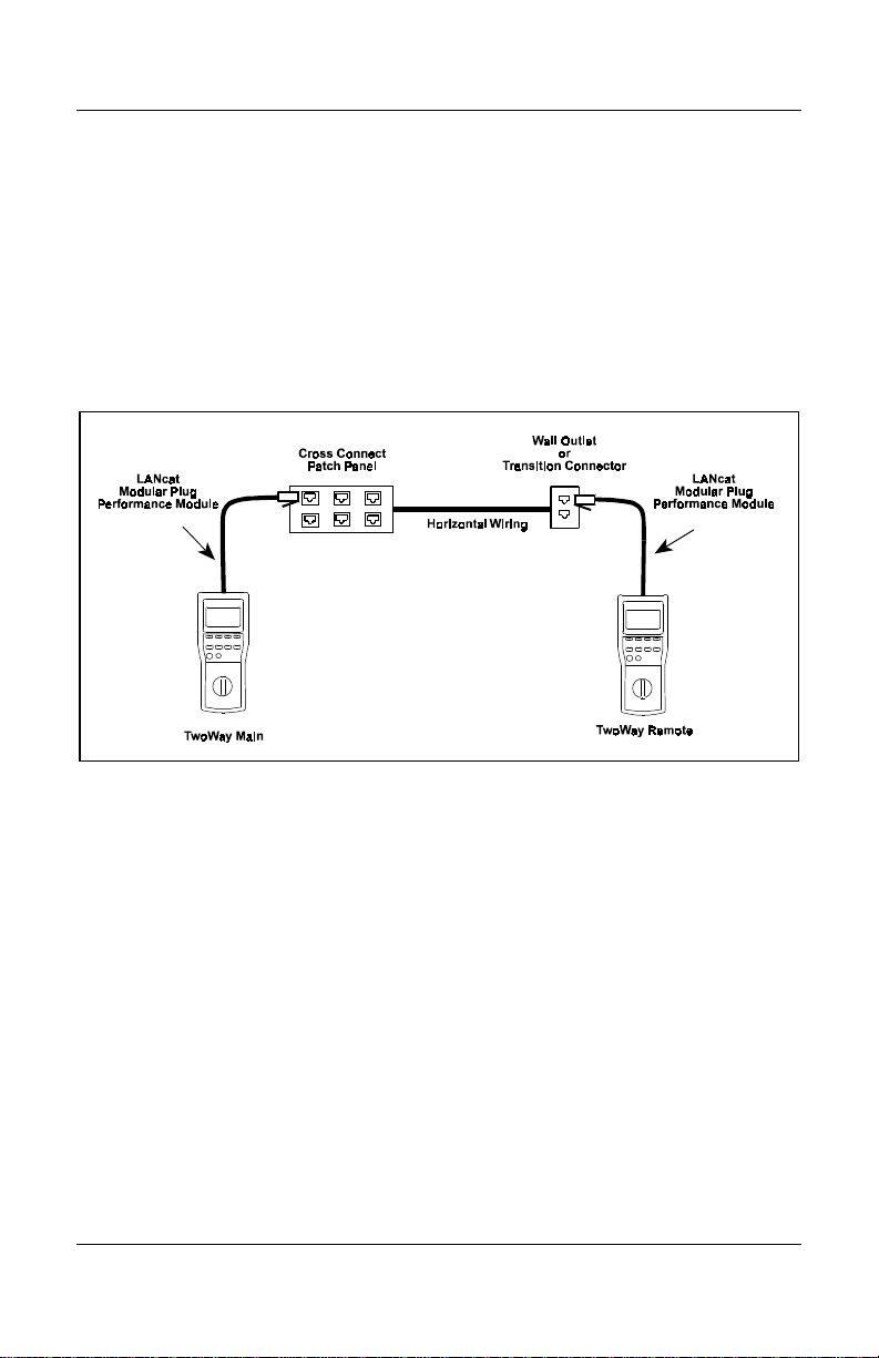
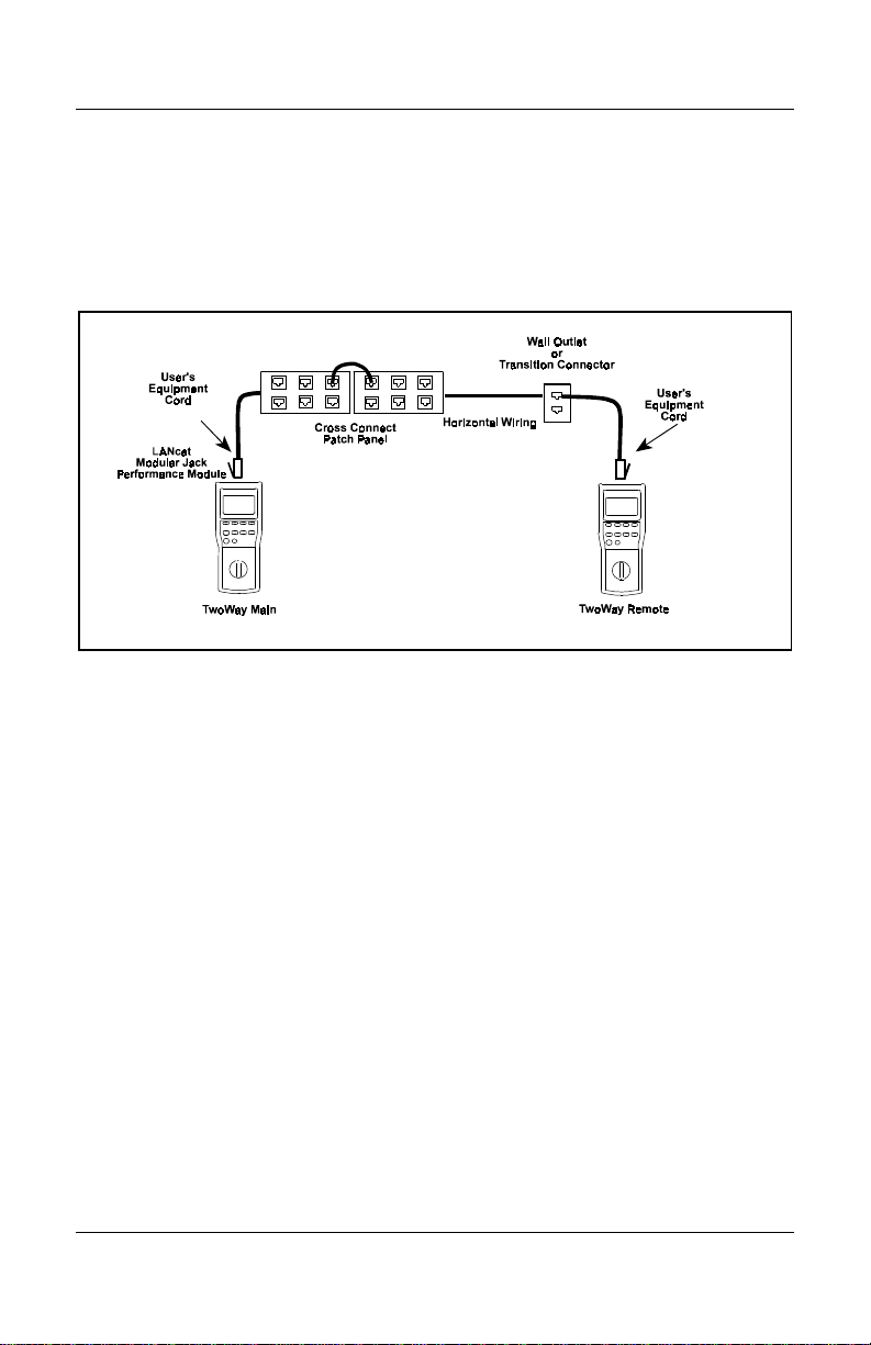
Typical Test Set Up
BASIC LINK TESTING
Figure 2-1 illustrates a typical test set up using a TwoWay System
to test a Basic Link, as defined by TIA/EIA TSB-67.
Figure 2-1. Typical TwoWay Test Set Up For Testing a Basic Link
Page 2-5
Artisan Technology Group - Quality Instrumentation ... Guaranteed | (888) 88-SOURCE | www.artisantg.com
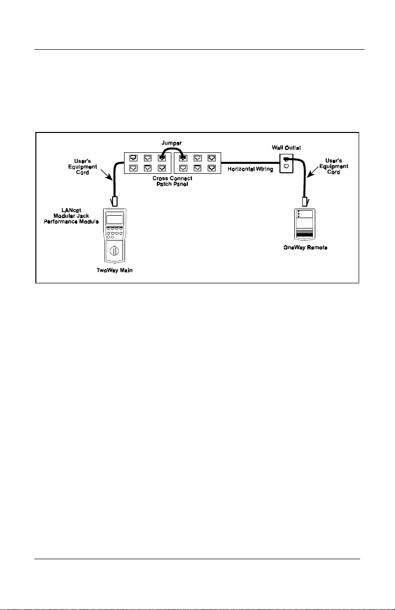
LANcat User Manual
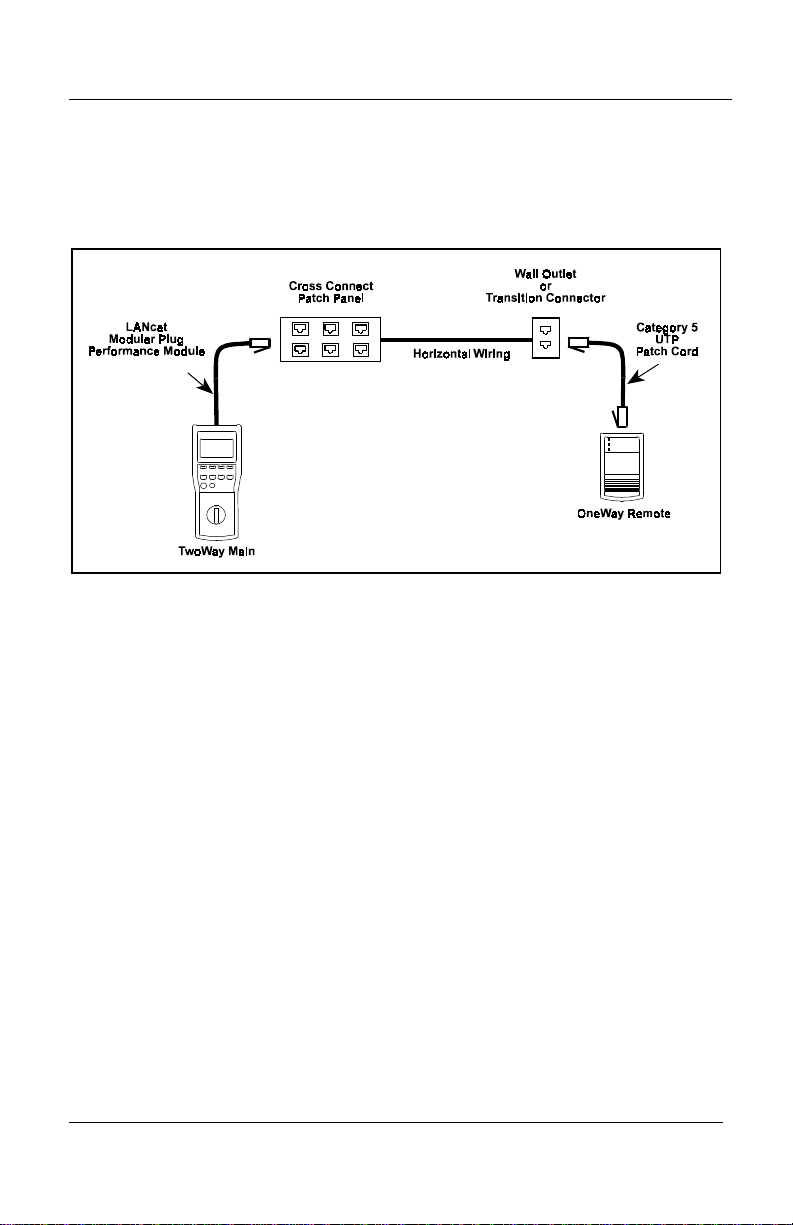
Figure 2-2 illustrates a typical test set up using a OneWay System
to test a Basic Link as defined by TIA/EIA TSB-67.
Figure 2-2. Typical OneWay Test Set Up For Testing a Basic Link
NOTE
To certify a cable link with Level II accuracy, you
must test the Basic Link using the LANcat Modular
Plug Performance Module. You must also test the
link from both ends (LANcat OneWay only). See
Appendix A, Test Standards for further information.
Page 2-6
Artisan Technology Group - Quality Instrumentation ... Guaranteed | (888) 88-SOURCE | www.artisantg.com
Chapter 2 Getting Started
CHANNEL TESTING
Figure 2-3 illustrates a typical test set up using a TwoWay System
to test a Channel as defined by TIA/EIA TSB-67.
Figure 2-3. Typical TwoWay Test Set Up For Testing a Channel
Page 2-7
Artisan Technology Group - Quality Instrumentation ... Guaranteed | (888) 88-SOURCE | www.artisantg.com
LANcat User Manual
Figure 2-4 illustrates a typical test set up using a OneWay System
to test a channel as defined by TIA/EIA TSB-67.
Figure 2-4. Typical OneWay Test Set Up For Testing a Channel
NOTE
A channel can be certified for conformance to the
TIA/EIA TSB-67 Link Performance Standard,
however, accuracy will be less than Level II
requirements. See Appendix A, Test Standards for
further information.
Page 2-8
Artisan Technology Group - Quality Instrumentation ... Guaranteed | (888) 88-SOURCE | www.artisantg.com
Chapter 2 Getting Started
Selecting a Cable Test Standard
The Cable Test Standard used by the LANcat to certify cables may
be changed any time
To select a different cable test standard:
1. Set dial to Autotest, Quick , Wire Map, Length or Traffic.
2. Press either arrow key to display the cable standard library and
select a different cable test standard.
appears next to the cable name.
3. When the desired cable test standard is highlighted, press
SELECT (F4) or ENTER. The LANcat immediately begins
testing using the new cable test standard.
NOTE
Refer to Appendix A, Test Standards, for assistance in
choosing an appropriate cable test standard.
When using a TwoWay System, cable standards are
compared at both ends. If they differ, the standard on the
Remote end will automatically be changed to match that of
the Main end.
Page 2-9
Artisan Technology Group - Quality Instrumentation ... Guaranteed | (888) 88-SOURCE | www.artisantg.com

LANcat User Manual
System Integrity Pre-Test
Before testing an installation, the integrity of the LANcat system
may be checked by running the tests described below.
To pre-test your system:
1. Connect the main and remote units using a CAT3 coupler or a
patch cable.
2. Run Self Test (Extended Functions, see Chapter 11).
3. Run Pair Reversal (Extended Functions, see Chapter 5).
4. Run Repeatability (Extended Functions, see Chapter 5).
5. Run Autotest (CAT3 Basic Link, see Chapter 3).
6. If FAIL occurs on any test results, contact Datacom Textron
Technical Support for assistance
(see Chapter 11).
Page 2-10
Artisan Technology Group - Quality Instrumentation ... Guaranteed | (888) 88-SOURCE | www.artisantg.com
 Loading...