

Datacom Systems VS-1112-F, VS-1012-F, VS-1024-F, VS-1212-F, VS-1124-F Fast Start Manual
...Page 1

VS-1012-F, VS-1024-F, VS-1112-F
VS-1124-F, VS-1212-F, VS-1224-F
Network Packet Brokers
FASTstart Guide
December 2015
© 2015 Datacom Systems Inc
Page 2

© 2015 Datacom Systems Inc
2
VS-10XX-F, VS-11XX-F, VS-12XX-F FASTstart Guide
Table of Contents
1 Terms of Use ............................................................................................................................................... 3
1.1 Copyright ......................................................................................................................................................... 3
1.2 License Agreement ........................................................................................................................................ 3
1.3 Proprietary Notice .......................................................................................................................................... 3
1.4 Trademark Attribution .................................................................................................................................... 3
1.5 Certifications and Marks ................................................................................................................................. 3
1.6 Safety Notices and Warnings .......................................................................................................................... 4
2 Overview .................................................................................................................................................... 5
2.1 What Shipped? ............................................................................................................................................... 6
2.2 Specifications .................................................................................................................................................. 6
2.3 Supported SFP Transceivers ........................................................................................................................... 7
2.4 Front — Any-to-Any Ports .............................................................................................................................. 7
2.5 Front — Power & Status Indicators ............................................................................................................... 8
2.6 Front — Display and Buttons ......................................................................................................................... 8
2.7 Rear — Power Module ................................................................................................................................... 9
2.8 Rear — Management Module ........................................................................................................................ 9
3 Network IP Address Configuration ................................................................................................................ 10
3.1 Default Settings ............................................................................................................................................ 10
3.2 Setting up the VERSAstream for Management Port Access ....................................................................... 11
4 Management Connection .......................................................................................................................... 13
4.1 Setup ............................................................................................................................................................. 13
4.2 Connecting via Telnet/SSH ............................................................................................................................ 14
4.3 Web Browser ................................................................................................................................................. 17
5 Configuration Examples ............................................................................................................................ 19
5.1 Media Conversion ......................................................................................................................................... 19
5.2 Aggregation ................................................................................................................................................... 20
5.3 Load Balancing ................................................................................................. Error! Bookmark not defined.
5.4 Filtering ......................................................................................................................................................... 24
6. Customer Service ..................................................................................................................................... 26
Page 3

© 2015 Datacom Systems Inc
3
VS-10XX-F, VS-11XX-F, VS-12XX-F FASTstart Guide
1 Terms of Use
The following terms and conditions relate to the use of this document. Please note that Datacom
Systems Inc. reserves the right, at its entire discretion, to change, modify, add, or remove portions of
these Terms of Use at any time. Please read the Terms of Use carefully as your use of this document
is subject to the Terms of Use stipulated herein.
1.1 Copyright
Copyright ©2015 by Datacom Systems, Inc. All rights reserved. Printed in the United States of
America. No part of this publication may be reproduced, stored in a retrieval system, or transmitted,
in any form or by any means, electronic, mechanical, photocopying, recording, or otherwise, without
the prior written permission of Datacom Systems, Inc.
1.2 License Agreement
Notice to All Users: By using Datacom Systems, Inc. products, you agree to the terms set forth. No
licenses, express or implied, are granted with respect to the technology described and Datacom
Systems, Inc. retains all rights with respect to the technology described herein. If applicable, you
may return the product to the place of purchase for a full refund.
1.3 Proprietary Notice
This document contains proprietary information about the VS-1012-F, VS-1112-F, VS-1212-F, VS1024-F, VS-1124-F, and VS-1224-F Data Access Switches Command Line Interface (CLI) and is
not to be disclosed or used except as authorized by written contract with Datacom Systems, Inc.
1.4 Trademark Attribution
Access Your Network™ , DURAstream™ , SINGLEstream™ , and VERSAstream™ , are
trademarks of Datacom Systems, Inc. All other registered and unregistered trademarks are the sole
property of their respective owners. All specifications may be changed without notice.
1.5 Certifications and Marks
For information regarding certifications and marks, please refer to the product info section of our
website at http://www.datacomsystems.com
Page 4

© 2015 Datacom Systems Inc
4
VS-10XX-F, VS-11XX-F, VS-12XX-F FASTstart Guide
1.6 Safety Notices and Warnings
These explanatory labels are included in this information for the user in accordance
with the requirements of IEC 60825.1.
WARNING
A class 1 laser is safe under all conditions of normal use. Invisible laser radiation may
be emitted from optical port openings when no fiber cable is connected, avoid exposure
to laser radiation and do not stare into open optical ports.
IMPORTANT: Rack Mount Instructions are included here to call the attention of installation technicians to
pertinent safety and warning issues prior to the installation of the product as follows:
A.
Elevated Operating Ambient — If installed in a closed or multi-unit rack assembly, the operating ambient
temperature of the rack environment may be greater than room ambient. Therefore, consideration should
be given to installing the equipment in an environment compatible with the maximum ambient temperature
specified.
B.
Reduced Air Flow — Installation of the equipment in a rack should be such that the amount of air flow
required for safe operation of the equipment is not compromised.
C.
Mechanical Loading — Mounting of the equipment in the rack should be such that a hazardous condition is
not achieved due to uneven mechanical loading.
D.
Circuit Overloading — Consideration should be given to the connection of the equipment to the supply
circuit and the effect that overloading of the circuits might have on over-current protection and supply
wiring. Approp riate consideration of equipment nameplate ratings should be used when addressing this
concern.
E.
E.
Reliable Earthing — Reliable earthing of rack- mounted equipment should be maintained. Particular
Reliable Earthing — Reliable earthing of rack- mounted equipment should be maintained. Particular
attention should be given to supply connections other than direct connections to the branch circuit (e.g.
attention should be given to supply connections other than direct connections to the branch circuit (e.g.
use of power strips).
use of power strips).
F. N
o user servicable parts inside. Do not open the product. Product must be returned to factory for repair.
: When used with any
Class 1 laser and LED products. (SFP+/SFP transceivers)
Page 5

© 2015 Datacom Systems Inc
5
VS-10XX-F, VS-11XX-F, VS-12XX-F FASTstart Guide
2 Overview
This FASTstart Guide for the VS-10XX-F, VS-11XX-F, and the VS-12XX-F Network Packet
Brokers is intended to provide you with information needed to get your Network Packet Broker up
and running. Additional support, documentation and help can be found on the Datacom Systems
website: http://www.datacomsystems.com
Network Packet Brokers increase network visibility and leverages your investment in network
analyzers, probes, and security equipment. The Network Packet Broker filtering and load balancing
functionality allows you to "lighten the load" to your network analyzers, probes, and security
equipment by allowing you to filter only the data you want to monitor and distribute it among the
tools evenly. Greater selectivity and visibility accelerates problem resolution, reduces downtime and
increases enterprise productivity.
Like all Datacom Systems Data Access Products, the VERSAstream Network Packet Brokers are
compatible with all vendor hardware and can be controlled by web browser based software or
Command Line Interface (CLI), which will allow you to control all of your Network Packet Broker
products through a single interface regardless of what network appliances you choose to deploy.
Page 6

© 2015 Datacom Systems Inc
6
VS-10XX-F, VS-11XX-F, VS-12XX-F FASTstart Guide
2.1 What Shipped?
1 - VS-1012-F, VS-1112-F, VS-1212-F, VS-1024-F, VS-1124-F, or VS-1224-F
2 - AC Line Cords
1 - DRL512-2M-R cables, DB9 M/F straight through
2.2 Specifications
VS-1012-F, VS-1112-F, VS-1212-F Ports:
12 - SFP; SFP+*
VS-1024-F, VS-1124-F, VS-1224-F Ports:
24 - SFP; SFP+*
*Only VS-11XX-F, and VS-12XX-F models support SFP+.
Management Port (rear):
RJ45 @ 10/100/1000 Mb Full-Duplex
Serial Port (rear):
DB9 @ 115,200 bps; 8 data bits; Parity none; 1 stop bit; Flow control none
Input Power Requirement:
100-240VAC 50-60Hz, 4.0-2.0 A
Dimensions (H x W x D):
1.72 x 19.00 x 20.50 inch (4.37 x 48.26 x 52.07 cm)
Weight:
18.15 lbs (8.23 kg)
Operating Temperature:
32º to 104° F (0º to 40° C)
Storage Temperature:
-22º to 149° F (-30º to 65° C)
Humidity:
Less than 95° C non-condensing
Warranty:
Visit http://www.datacomsystems.com/support/warranty-info for more
information.
Page 7

© 2015 Datacom Systems Inc
7
VS-10XX-F, VS-11XX-F, VS-12XX-F FASTstart Guide
Model #
Specification
FTLF1318P3BTL
1000BASE-LX
FTLF1319F1GTL
1000BASE-LX
FTLF8519P3BTL
1000BASE-SX Ethernet
FTLX1412D3BCL
10GBASE-LR, 10GBASE-LW
FTLX1471D3BCV
1000BASE-LX, 10GBASE-LR, 10GBASE-LW
FTLX1612M3BCL
10GBASE-ER, 10GBASE-EW, 10GBASE-ER/EW + FEC
FTLX1671D3BCL
10GBASE-ER, 10GBASE-EW
FTLX1811M3
10GBASE-ZR, 10GBASE-ZW
FTLX8511D3
10GBASE-SR, 10GBASE-SW
FTLX8512D3BCL
10GBASE-SR, 10GBASE-SW
FTLX8571D3BCL
10GBASE-SR, 10GBASE-SW
FTLX8571D3BCV
1000BASE-SX, 10GBASE-SR, 10GBASE-SW
2.3 Supported SFP Transceivers
Datacom Systems supports the following small form-factor pluggable (SFP) transceivers and
enhanced small form-factor pluggable (SFP+) transceivers:
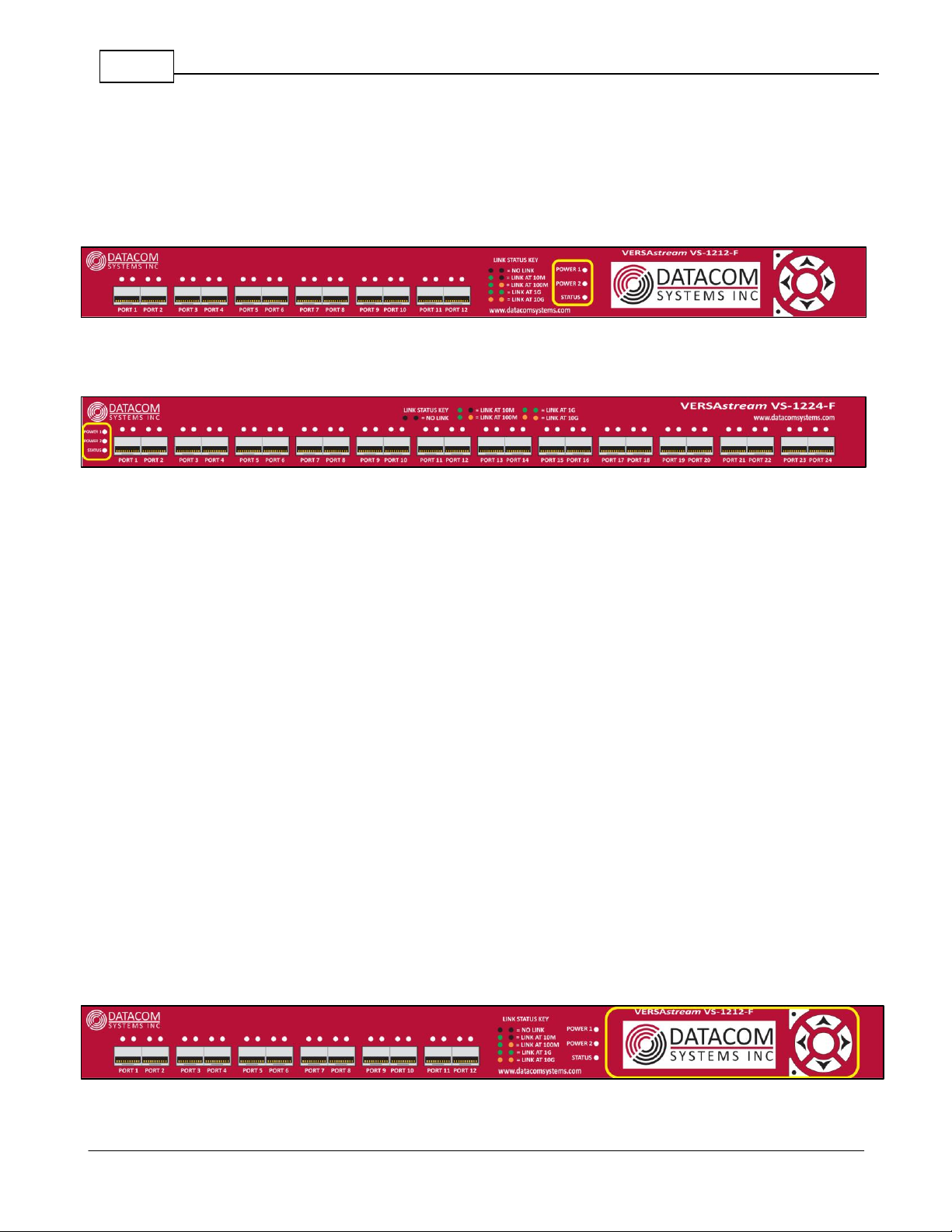
2.4 Front — Any-to-Any Ports
When receiving traffic, the Any-to-Any ports on the front of the VERSAstream can be connected to
Tap outputs, SPAN ports, and mirror ports.
When transmitting traffic, the Any-to-Any ports can be connected to devices such as security
probes, intrusion detection systems (IDS), and packet analyzers.
12-Port Versions
24-Port Versions
Page 8
© 2015 Datacom Systems Inc
8
VS-10XX-F, VS-11XX-F, VS-12XX-F FASTstart Guide
2.5 Front — Power & Status Indicators
On the front panel, the power status of the device can be determined through three indicators labeled
“POWER 1”, “POWER 2”, and “STATUS”.
12-Port Versions
24-Port Versions
The LEDs located next to each power label will illuminate green when a power supply is
connected and switched ON.
When the power indicators illuminate red, it indicates that there either is not a power supply
connected, or it is not switched ON.
Although only one power source is required to power the VERSAstream, use of a second
independent power source is strongly recommended to assure uninterrupted monitoring.
The “STATUS” LED indicator is orange during the boot-up cycle and turns green upon a
successful boot sequence indicating the VERSAstream is operational.
NOTE: The “STATUS” LED indicator indicates the device is ready several seconds before it is
ready to respond to Command Line Interface (CLI) commands.
2.6 Front — Display and Buttons
The display shows Serial and Management Port status. The Selectable Buttons are for future
use.
12-Port Versions Only
Page 9
© 2015 Datacom Systems Inc
9
VS-10XX-F, VS-11XX-F, VS-12XX-F FASTstart Guide
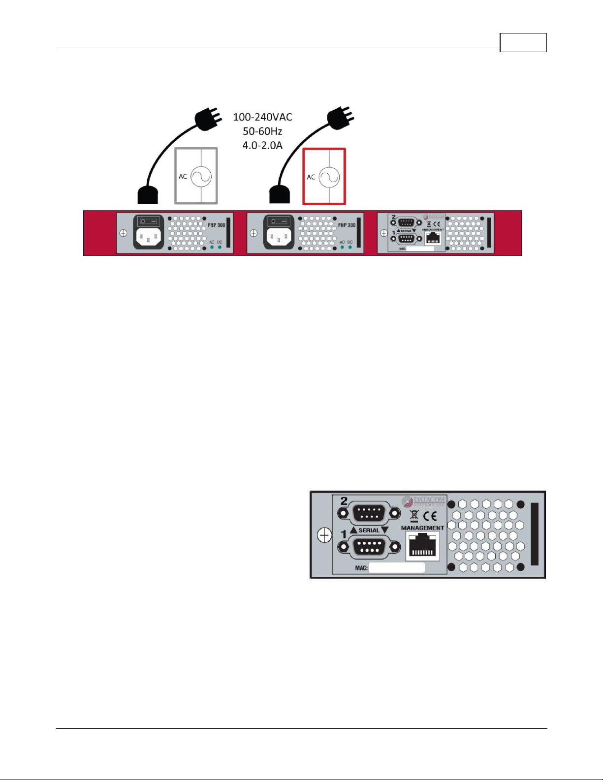
2.7 Rear — Power Module
Each VERSAstream has two power modules on the back. These are for dual redundant power
supplies and should be connected to two separate circuits to ensure uninterrupted monitoring. Each
power module has an AC power socket, an AC power switch, and two LED indicators labeled “AC”
and “DC”. These LED indicators function in unison with the “POWER 1”, and “POWER 2”
indicators on the front of the device.
The LEDs located next to the “AC” and “DC” labels will illuminate green when a power supply is
connected and switched ON.
If either LED is illuminated red, it indicates a defective power source. Immediate investigation is
recommended to insure redundant power integrity.
2.8 Rear — Management Module
The SERIAL 1 connector port is a shielded DB9
Female. This port can be connected to the COM
port of any compatible network tool or PC in
order to access the Command Line Interface for
device configuration.
The SERIAL 2 connector port is reserved for future use.
The MANAGEMENT connector port is a shielded RJ45 and is cabled to the network.
The Media Access Control (MAC) address identifier and certification compliance identifiers are
provided on this rear label.
Page 10

© 2015 Datacom Systems Inc
10
VS-10XX-F, VS-11XX-F, VS-12XX-F FASTstart Guide
SSH and Telnet
Port: 22 and 23
Serial Terminal Settings
Bits per second: 115200
Data bits: 8
Parity: None
Stop: 1
Flow Control: None
Management Port Settings
IP Address: 192.168.1.1
Subnet Mask: 255.255.0.0
Default Gateway: 192.168.0.1
User Settings
Username: Administrator
Password: admin
3 Network IP Address Configuration
All VERSAstream Network Packet Brokers can be accessed and configured though the
management port on the rear panel of the unit. Once set up, this port can be used to access the
device through Telnet, SSH, or HTTPS.
3.1 Default Settings
All Network Packet Broker series units are shipped with a factory default configuration as follows:
IMPORTANT: If you expect to remotely connect to the VERSAstream series, you must
change the IP Address, Subnet Mask and Gateway to match your Local Area Network.
In order to initially change the IP settings on the management port, you must connect to the device
over the serial port.
Page 11

© 2015 Datacom Systems Inc
11
VS-10XX-F, VS-11XX-F, VS-12XX-F FASTstart Guide
3.2 Setting up the VERSAstream for Management Port Access
Step 1: First, connect your PC and your VERSAstream using the provided Datacom Systems
DRL512-2M-R cable. Connect the DB9 Female pin end to the serial port on your PC and connect
the DB9 Male pin to the SERIAL 1 port on your VERSAstream.
NOTE: For PCs without 9-pin serial ports, check with your product representative for available
sources of a USB RS-232 Serial Adapter.
Step 2: Using the supplied AC Line Cord(s), plug the VERSAstream into an external power source.
Depress the AC power switch bar icon to power ON the VERSAstream, which will be soon
followed by the internal cooling fans powering up.
Step 3: Open the terminal emulation application (PuTTy or Tera Term for example) on your PC,
and use it establish a serial connection to the VERSAstream.
Step 4: Once connected, hitting the Enter key twice in a row will bring up the login prompt. Log in
to the VERSAstream with the default credentials of “Administrator” and then “admin”.
Page 12

© 2015 Datacom Systems Inc
12
VS-10XX-F, VS-11XX-F, VS-12XX-F FASTstart Guide
Step 5: Set up the IP address, subnet, and gateway on the device to match the network that the
management port is connected to. This can be done by using the commands:
o SET IP <IP address>
o SET SUBNET <Subnet mask>
o SET GATEWAY <Gateway IP address>
o EXIT
You must enter the “exit” command and log back into the VERSAstream before the changes are
applied.
Step 6: Once you have logged back in to the device, enter the “show management” command. This
will display setting information regarding the management port. Verify that the settings are correct.
You may choose to configure the VERSAstream using either the serial port or the management port.
All configuration capabilities will be the same for each type.
Page 13

© 2015 Datacom Systems Inc
13
VS-10XX-F, VS-11XX-F, VS-12XX-F FASTstart Guide
4 Management Connection
4.1 Setup
Once the management port configuration on the VERSAstream has been set up to match your
chosen network location, you must next connect the straight through CAT5 cable to your network.
NOTE: In situations where the management port is connected directly to a laptop or PC, a crossover
cable may be required.
When the cable is connected, the LED light on the left side of the port will illuminate green. This
indicates that a link has been established with the device on the other end of the cable. The LED on
the right side of the port will occasionally blink green when traffic is being passed.
To confirm that there is connectivity between the VERSAstream and the connected device, open a
terminal and ping the IP address of the VERSAstream.
Page 14

© 2015 Datacom Systems Inc
14
VS-10XX-F, VS-11XX-F, VS-12XX-F FASTstart Guide
4.2 Connecting via Telnet/SSH
Once the Management port is configured and connected to the network, the VERSAstream may be
configured using a CLI over Telnet or SSH.
After confirming in step 4.1 that the VERSAstream is accessible over the network, a terminal
emulator may be used to configure the device.
The following steps show the process for connecting to the VERSAStream through either Telnet or
SSH. The images used in the steps are from the terminal emulator Tera Term. Most terminal
emulators can be used to connect to the VERSAStream, however using either Tera Term or Putty is
recommended.
Step 1: Open the terminal emulator. Select either Telnet or SSH as a method for connection.
Step 2: Enter the IP address of the VERSAstream in the Host field. Click “OK”
Page 15

© 2015 Datacom Systems Inc
15
VS-10XX-F, VS-11XX-F, VS-12XX-F FASTstart Guide
Note: If you select SSH, the following window will pop up on the first connection attempt to the
VERSAStream from the terminal. This is a security feature of SSH. Click connect.
Step 3: You will be presented with login prompt. This could appear in the form of a pop-up
window, or a terminal depending on the terminal emulator used. Default credentials are
“Administrator”, “admin”.
Page 16

© 2015 Datacom Systems Inc
16
VS-10XX-F, VS-11XX-F, VS-12XX-F FASTstart Guide
Step 4: To confirm that connection to the correct device was made, enter the “show” command to
view unique identifiers for the unit such as the Serial Number and MAC Address.
Note: For more information on CLI configuration, download the VS-1012-1024-1112-1124-12121224 Command Line Manual from the website at:
http://www.datacomsystems.com/resources/manuals
Page 17

© 2015 Datacom Systems Inc
17
VS-10XX-F, VS-11XX-F, VS-12XX-F FASTstart Guide
4.3 Web Browser
Once the Management port is configured and connected to the network, the VERSAstream may be
configured using a GUI over a HTTPS web session.
Note: Only HTTPS web sessions are supported. Unencrypted HTTP web sessions are not
supported and will be redirected to HTTPS.
To access the VERSAstream GUI, first open a web browser. Compatible web browsers include
Google Chrome 35, Microsoft Internet Explorer 11, and Mozilla Firefox 33.
Enter “https://” followed by the IP address of the VERSAstream and hit “Enter”.
You may be brought to a screen that asks you to confirm that you know the destination address.
This will look different on different browsers. Click “Proceed”, “Add Exception” or “Continue to
this website”.
Chrome
Page 18

© 2015 Datacom Systems Inc
18
VS-10XX-F, VS-11XX-F, VS-12XX-F FASTstart Guide
Firefox
Internet Explorer
Next, you will be brought to the GUI login screen. Enter the login credentials. Default is
“Administrator”, “admin”. Click “Log in”.
Note: Video guides for GUI configuration can be found at the bottom of the page at:
http://www.datacomsystems.com/resources/manuals
Page 19

© 2015 Datacom Systems Inc
19
VS-10XX-F, VS-11XX-F, VS-12XX-F FASTstart Guide
Command
Description
set port speed 1,5 10G
Sets ports 1 and 5 to 10G Fiber speed.
set port speed 2 1000X-Manual
Sets port 2 to 1G Fiber speed.
set port speed 3,4 CU-AUTO
Sets ports 3 and 4 to Auto copper speed.
show port config 1-5
Displays the configured speeds for ports 1-5.
1 2 3
4
5
5 Configuration Examples
5.1 Media Conversion
Use Case: There are 1G inputs with 10G monitors, or 10G inputs with 1G monitors. It is a
requirement that the speed/media of the traffic is converted so that the monitors can receive the
traffic.
The VERSAstream series is SFP based and can convert from one media type and speed to another.
1. To set up the above configuration on a VERSAstream, the first step is to install the correct SFP
types to connect to the devices on either end.
2. The next step is to configure the ports on the device to match the speed of the devices connected
to them (For example, choosing between Auto-Negotiation copper or manually set speed).
Page 20

© 2015 Datacom Systems Inc
20
VS-10XX-F, VS-11XX-F, VS-12XX-F FASTstart Guide
Command
Description
set port monitor 4 from 1
Directs traffic incoming from port 1 out port 4.
set port monitor 5 from 2,3
Directs traffic incoming from ports 2, 3 out port 5.
show port routing
Displays all traffic steering configurations.
1 2 3 4 5
3. Finally, Port-Steering must be set up on the configuration of the device to direct traffic flow
from the inputs to the outputs.
The speed and media type of traffic will now be converted by the VERSAstream. This gave the
monitors access to data streams that were in a previously incompatible format.
5.2 Aggregation
Use Case: There are multiple SPAN and TAP inputs and a single (1G or 10G) monitor. Traffic
needs to be taken from the SPAN and TAP inputs and combined into a single output link.
1. To set up the above configuration on a VERSAstream, the first step is to install the correct SFP
types to connect to the devices on either end.
Page 21

© 2015 Datacom Systems Inc
21
VS-10XX-F, VS-11XX-F, VS-12XX-F FASTstart Guide
Command
Description
set port speed 1,4 CU-AUTO
Sets ports 1 and 4 to Auto copper speed.
set port speed 2,5 10G
Sets port 2 and 5 to 10G Fiber speed.
set port speed 3 1000X-Manual
Sets ports 3 to 1G Fiber speed.
show port config 1-5
Displays the configured speeds for ports 1-5.
Command
Description
set port monitor 5 from 1,2,3,4
Directs traffic incoming from ports 1out port 5.
show port routing
Displays all traffic steering configurations.
2. The next step is to configure the ports on the device to match the speed of the devices connected
to them (For example, choosing between Auto-Negotiation copper or manually set speed).
3. Finally, Port-Steering must be set up on the configuration of the device to direct traffic flow
from the inputs to the output.
Traffic from each of the TAPS and SPAN ports will be combined and sent to the IDS. This
allowed a single IDS to monitor traffic from many different sources.
Page 22

© 2015 Datacom Systems Inc
22
VS-10XX-F, VS-11XX-F, VS-12XX-F FASTstart Guide
Command
Description
set port speed 1 10G
Sets ports 1 to 10G Fiber speed.
set port speed 2,3,4,5 CU-AUTO
Sets port 2 through 5 to Auto copper speed.
show port config 1-5
Displays the configured speeds for ports 1-5.
1
2 3 4
5
5.3 Load Balancing
Use Case: There are a group of monitors to observe traffic from a high speed tapped link. The
amount of traffic coming from the link is greater than any of the individual monitors can monitor.
All of the traffic on the tapped link needs to be monitored by a set of Intrusion Detection Systems
(IDS).
1. To set up the above configuration on a VERSAstream, the first step is to install the correct SFP
types to connect to the devices on either end.
2. The next step is to configure the ports on the device to match the speed of the devices connected
to them (For example, choosing between Auto-Negotiation copper or manually set speed).
Page 23

© 2015 Datacom Systems Inc
23
VS-10XX-F, VS-11XX-F, VS-12XX-F FASTstart Guide
Command
Description
create group output_ports
Creates a port group named “output_ports”.
add group member output_ports 2,3,4,5
Adds ports 2, 3, 4, and 5 to the group.
show group output_ports
Shows the details for the group “output_ports”.
Command
Description
create lbc LBC1
Creates a LBC named “LBC1”.
set lbc ingress-ports LBC1 1
Sets port 1 as the ingress port for” LBC1”.
set lbc egress-ports LBC1 output_ports
Sets the port group “output_ports” as the egress
ports in LBC “LBC1”.
set lbc state LBC1 active
Activates the load balance group to start passing
traffic.
3. A port group must be created consisting of the 4 ports that are connected to the Intrusion
Detection Systems (IDS).
4. A load balancing configuration must be created to load balance traffic from the Tapped link to
the 4 IDSs.
Traffic from the Tapped link will now be load balanced to the 4 IDSs. The 1G monitoring
devices are able to share the traffic coming in from the 10G link. This allows them to not
become oversubscribed with traffic.
Page 24

© 2015 Datacom Systems Inc
24
VS-10XX-F, VS-11XX-F, VS-12XX-F FASTstart Guide
Command
Description
set port speed 1,2,5 10G
Sets ports 1,2, and 5 to 10G Fiber speed.
set port speed 3,4 CU-AUTO
Sets port 3 and 4 to Auto copper speed.
show port config 1-5
Displays the configured speeds for ports 1-5.
1 2 3 4 5
5.4 Filtering
Use Case: Traffic is coming in from TAP/SPAN ports exceeds the speed of the monitoring
devices that need to receive the traffic. Some of the monitoring devices only need to see part of the
data that is going over my TAP/ SPAN ports.
1. To set up the above configuration on a VERSAstream, the first step is to install the correct SFP
types to connect to the devices on either end.
2. The next step is to configure the ports on the device to match the speed of the devices connected
to them (For example, choosing between Auto-Negotiation copper or manually set speed).
Page 25

© 2015 Datacom Systems Inc
25
VS-10XX-F, VS-11XX-F, VS-12XX-F FASTstart Guide
Command
Description
set port monitor 3 from 1,2
Directs traffic incoming from ports 1, 2 out port 3.
set port monitor 4 from 1,2
Directs traffic incoming from ports 1, 2 out port 4.
set port monitor 5 from 1,2
Directs traffic incoming from ports 1, 2 out port 5.
show port routing
Displays all traffic steering configurations.
Command
Description
add filter IP1
(ip.src==192.168.1.20)
Creates a filter that only allows the IP address
of 192.168.1.20 and names it IP1.
add filter IP2
(!(ip.dst==192.168.1.25)
Creates a filter that blocks traffic with the IP
address of 192.168.1.25and names it IP2.
set port filter 3 egress IP2
Sets the IP2 filter to all traffic leaving port 3.
set port filter 4 egress IP1
Sets the IP1 filter to all traffic leaving port 4.
show port filter 3,4
Shows the filters applied to ports 3 and 4.
3. Port-Steering must be set up on the configuration of the device to direct traffic flow from the
inputs to the output.
4. Filters are created and applied to the ports connected to the monitors.
With this setup, traffic that is coming in from the TAP and SPAN ports is being filtered based
on specific criteria. The probe, packet analyzer, and IDS are able to receive only the traffic that
they need to see to be able to do their job.
Page 26

© 2015 Datacom Systems Inc
26
VS-10XX-F, VS-11XX-F, VS-12XX-F FASTstart Guide
6. Customer Service
Datacom Customer Service is available via telephone and Internet. You may also find the
assistance you need at our website: http://www.datacomsystems.com.
Telephone
Internet website:
:
+1 315 463-9541
http://www.datacomsystems.com/support/contact-support
Page 27

27
VS-10XX-F, VS-11XX-F, VS-12XX-F FASTstart Guide
Datacom Systems Inc.
9 Adler Drive • East Syracuse, NY 13057
TEL: +1 315 463-9541 • FAX: +1 315 463-9557
http://www.datacomsystems.com
 Loading...