

Page 1
Datacom Systems Inc
DS-1010 Bypass Switch
Access Your Network
TM
TM
DURA 10 Gigabit DS-1010
stream
USERguide
May 2010
© 2010 Datacom Systems Inc
541-0130-U-A.00
Page 2

This page intentionally left blank
© 2010 Datacom Systems Inc
Page 3

Product Description
Datacom Systems Inc. DURAstream™ DS-1010 Bypass Switch is a 10Gbps
intelligent external active bypass that enables plug and play connectivity which
includes an auto heartbeat and requires no additional drivers to be installed on
any connected appliance. The DS-1010 consists of one 10Gbps segment which
can support one network segment and one appliance.
Page 4

DURATMstream
© 2010 Datacom Systems Inc
All rights reserved. No parts of this work may be reproduced in any form or by
any means graphic, electronic, or mechanical, including photocopying, recording,
taping, or information storage and retrieval systems without the written
permission of the publisher.
Products that are referred to in this document may be either trademarks and/or
registered trademarks of the respective owners. The publisher and the author
make no claim to these trademarks.
While every precaution has been taken in the preparation of this document, the
publisher and the author assume no responsibility for errors or omissions, or for
damages resulting from the use of information contained in this document or
from the use of programs and source code that may accompany it. In no event
shall the publisher and the author be liable for any loss of profit or any other
commercial damage caused or alleged to have been caused directly or indirectly
by this document.
Printed: May 2010 in East Syracuse, New York
Page 5

Table of Contents
5
Table of Contents
Section 1 Terms of Use
.................................................................................................... 7
........................................................................................ 71 Copyright
........................................................................................ 72 License Agreement
........................................................................................ 73 Trademark Attribution
........................................................................................ 74 Proprietary Notice
........................................................................................ 85 Certifications and Marks
........................................................................................ 96 Safety Notices and Warnings
Section 2 Overview
.................................................................................................... 10
........................................................................................ 111 Shipped Contents
........................................................................................ 112 DURAstream™ Series Benefits and Features
........................................................................................ 123 DS-1010 Series Common Specifications
........................................................................................ 124 DS-1010 Series Specific Specifications
........................................................................................ 135 Technical Brief
Section 3 Hardware Interface
.................................................................................................... 14
........................................................................................ 141 Device Management
........................................................................................ 142 Port LED Interface
........................................................................................ 143 LCD Interface
Section 4 Theory of Operation
.................................................................................................... 15
........................................................................................ 161 Operation Modes
1 Normal Active Bypass
2 Normal Active Inline
3 Manual Active Inline
4 Manual Active Bypass
5 Manual Passive Bypass
............................................................................................... 17
............................................................................................... 18
............................................................................................... 19
............................................................................................... 19
............................................................................................... 20
........................................................................................ 212 Heartbeat (Hb)
........................................................................................ 213 Power Failure Protection
Section 5 Initial Configuration
.................................................................................................... 22
........................................................................................ 221 Command Line Interface (CLI)
1 Basic Functionality
2 Basic Command Set
3 <variable> List for CLI
4 Command Line Interface Usage
............................................................................................... 22
............................................................................................... 22
............................................................................................... 23
............................................................................................... 26
........................................................................................ 272 SERIAL Port Configuration (RJ45)
1 HyperTerminal
2 IP Address Configuration
............................................................................................... 27
............................................................................................... 27
© 2010 Datacom Systems Inc
DURAstream™
Page 6

6
Table of Contents
Section 6 MANAGEMENT Port Configuration (RJ45)
.................................................................................................... 28
........................................................................................ 281 SSH Setting
........................................................................................ 282 User Account
........................................................................................ 283 Password
........................................................................................ 284 SNMP
1 Support
2 CLI Setup
............................................................................................... 28
............................................................................................... 29
........................................................................................ 295 TACACS+ Setup
........................................................................................ 296 NTP Definitions
........................................................................................ 297 SYSLOG Definitions
Section 7 Secure Web Management
.................................................................................................... 30
........................................................................................ 301 Login
........................................................................................ 312 Status
........................................................................................ 313 Bypass Module
........................................................................................ 314 Management Port
........................................................................................ 325 eMail Notifications
........................................................................................ 326 SNMP Settings
........................................................................................ 327 NTP Settings
........................................................................................ 338 Time Settings
........................................................................................ 339 Backup/Restore
........................................................................................ 3310 Firmware Update
........................................................................................ 3311 Log Settings
........................................................................................ 3412 Reboot
........................................................................................ 3413 Users
........................................................................................ 3414 TACACS+
Section 8 Appendix 1 Heartbeat frame format
Section 9 Appendix 2 Console-Cable Drawing
Section 10 Customer Service
.................................................................................................... 35
.................................................................................................... 36
.................................................................................................... 38
........................................................................................ 381 Internet
........................................................................................ 382 Warranty
........................................................................................ 383 Limits of Liability
DURAstream™
© 2010 Datacom Systems Inc
Page 7

Terms of Use
1 Terms of Use
The following terms and conditions relate to the use of this document. Please note that Datacom Systems
Inc. reserves the right, at its entire discretion, to change, modify, add, or remove portions of these Terms of
Use at any time. Please read the Terms of Use carefully as your use of this document is subject to the Terms
of Use stipulated herein.
1.1 Copyright
Copyright© 2010 by Datacom Systems, Inc. All rights reserved. Printed in the United States of America.
No part of this publication may be reproduced, stored in a retrieval system, or transmitted, in any form or
by any means, electronic, mechanical, photocopying, recording, or otherwise, without the prior written
permission of Datacom Systems, Inc. To obtain this permission, write to the attention of the Datacom
Systems legal department at 9 Adler Drive, East Syracuse, New York 13057-1290, or call 315-463-
9541.
1.2 License Agreement
Notice To All Users: By using Datacom Systems, Inc. products, you agree to the terms set forth. No
licenses, express or implied, are granted with respect to the technology described and Datacom Systems,
Inc. retains all rights with respect to the technology described herein. If applicable, you may return the
product to the place of purchase for a full refund.
7
1.3 Trademark Attribution
Access Your Network , DURAstream™, DS3 ACTIVEtap , DS3switch , ETHERNETtap ,
Empowering Network Professionals , FDDIswitch , FIBERsplitter , FIBERswitch ,
FIBERSWITCHsystem , FLOWcontrol , GIGABITswitch , INSERTswitch , INSERTunit , LAN
switch , MANAgents , MULTINETswitch , NETspan , PERMAlink , PROline , RMON
SWITCHINGanalyzer , SINGLEstream , UNIVERSALswitch , VERSAstream , and WANswitch
are trademarks of Datacom Systems, Inc. 1ST in Switching Solutions®, DATACOMsystems®, LAN
clipper®, MANAgents®, and MULTIview® are registered trademarks of Datacom Systems, Inc. All other
registered and unregistered trademarks are the sole property of their respective owners. All specifications
may be changed without notice.
1.4 Proprietary Notice
This document contains proprietary information about the DS-1010 family of products and is not to be
disclosed or used except as authorized by written contract with Datacom Systems, Inc.
1.4 Certifications and Marks
For information regarding certifications and marks, please refer to the product info section of our
website at http://www.datacomsystems.com
© 2010 Datacom Systems Inc
DURAstream™
Page 8

Terms of Use
1.6 Safety Notices and Warnings
These explanatory labels are included in this information for the user in accordance
with the requirements of IEC 60825.1.
WARNING: Class 1 laser and LED product. A class 1 laser is safe under all
conditions of normal use. Invisible laser radiation may be emitted from optical
port openings when no fiber cable is connected, avoid exposure to laser
radiation and do not stare into open optical ports.
IMPORTANT: Rack Mount Instructions are included here to call the attention of installation technicians to
pertinent safety and warning issues prior to the the installation of the product as follows:
A.
Elevated Operating Ambient — If installed in a closed or multi-unit rack assembly, the operating ambient
temperature of the rack environment may be greater than room ambient. Therefore, consideration should
be given to installing the equipment in an environment compatible with the maximum ambient temperature
(Tma) specified in the 'DS-1010 Series Common Specifications ' section.
12
9
B.
Reduced Air Flow — Installation of the equipment in a rack should be such that the amount of air flow
required for safe operation of the equipment is not compromised.
C.
Mechanical Loading — Mounting of the equipment in the rack should be such that a hazardous condition
is not achieved due to uneven mechanical loading.
D.
Circuit Overloading — Consideration should be given to the connection of the equipment to the supply
circuit and the effect that overloading of the circuits might have on over-current protection and supply
wiring. Appropriate consideration of equipment nameplate ratings should be used when addressing this
concern.
E.
Reliable Earthing — Reliable earthing of rack-mounted equipment should be maintained. Particular
attention should be given to supply connections other than direct connections to the branch circuit (e.g.
use of power strips).
© 2010 Datacom Systems Inc
DURAstream™
Page 9

10
Overview
2 Overview
Automatic Failover = Constant Link State — Deploying in-line monitoring devices such as intrusion
prevention systems (IPS) or bridge devices like VPN gateways and firewalls used to mean a potential point
of failure on the network. When one of these devices malfunctioned or became overwhelmed with traffic,
network outages could occur. This posed serious challenges when deployed on mission critical links.
The DURAstream™ Bypass Switch ensures your network’s most important data does not fail even when
in-line devices do. Deploying a DURAstream™ Bypass Switch ensures uptime of critical links regardless
of in-line device performance by diverting critical network traffic away from malfunctioning in-line devices
until such devices are operating normally. This not only alleviates potential issues with traffic congestion
affecting link behavior caused by an IPS, it allows maintenance and upgrades of attached in-line tools
without network downtime.
The DURAstream™ DS-1010 10G Bypass Switch is an easy-to-manage external active bypass providing
failover and TAP capabilities for data monitoring of critical Gigabit network segments. Each bypass switch
offers up to four independent interface modules with a variety of media options (copper, fiber, and media
conversion). Each of the four network modules operates independently to ensure link protection monitoring
of one to four links at any time.
Line-rate throughput and real-time data forwarding hardware protects data and allows critical voice and
data applications to perform uninterrupted and meet high demands for quality and security. Deployed with
an in-line monitoring tool, a DURAstream™ Bypass Switch creates a comprehensive solution for intrusion
prevention.
Heartbeat Mode — The DURAstream™ DS-1010 10G Bypass Switch can monitor the health of in-line
appliances by sending and receiving a heartbeat packet. A user programmable heartbeat packet can be
injected into the monitoring port link to determine availability of attached monitoring devices or help
determine delay due to high traffic volume. Even if a connected in-line tool is powered on, the bypass switch
can automatically switch traffic around it until the device returns to normal operation. At that time, traffic is
re-routed back to the monitor port.
Passive Mode — In the event of power loss, the switch closes to create a physical connection, which in
turn, creates a passive bypass path to help prevent traffic interruption. Robust Management, Security and
Logging Manage your switch using built-in CLI or GUI, including secure web interface over HTTPS.
Supports secure shell (SSH), SNMP, e-mail notifications, TACACS+ as well as Syslog to enable
consolidation of log data from multiple systems into a central repository.
Reliable and Easy to Use — The DURAstream™ DS-1010 10G Bypass Switch is simple to deploy,
enables plug-and-play connectivity, and is compatible with all major manufacturer’s monitoring systems.
Every unit not only comes with dual redundant power supplies to ensure monitoring uptime, the voltage of
each power supply is continuously monitored for instances of power decline or outage. In such cases, the
unit can initiate a switch to passive bypass mode.
DURAstream™
© 2010 Datacom Systems Inc
Page 10

Overview
2.1 Shipped Contents
DS-1010 Series Link Aggregation Taps
1 — Model: DS-1010 series Bypass Switch
1 — Console Cable (DB9 to RJ45)
1 — Management Cable (RJ45 to RJ45)
2 — Switching AC Adapters
2 — AC Line Cords
2.2 DURAstream™ Series Benefits and Features
Benefits
Optimized reliability of critical network links
Achieve fail-safe monitoring with in-line monitoring tools such as IPS and DPI
Improved network uptime and security
Increased application availability
Upgrade, maintain, or replace in-line devices without interrupting network operations
11
Datacom Customer Service Support is available via:
Phone: (315) 463-9541
Fax: (315 ) 463-9557
Website: www.datacomsystems.com
E-mail: support@datacomsystems.com
Features
Passive bypass maintains network integrity during power loss
Active switching of traffic in case of system failure to prevent network interruptions
Heartbeat Mode - several user-configurable options to monitor link status and health of inline appliances
including bridge devices like firewalls and VPN gateways
Flexible deployment options - single mode and multi-mode
Dual redundant power supplies ensure monitoring uptime
Power fail protection monitors power supplies for power decline or outage and can switch to passive
mode
Manage device remotely or locally with Web based management (HTTPS) or extensive CLI
Management port with SSH connectivity
SNMP traps and e-mail event notifications on defined events
Interfaces with authentication servers such as TACACS+
Syslog support
© 2010 Datacom Systems Inc
DURAstream™
Page 11

12
2.3 DS-1010 Series Common Specifications
Overview
One In-Line Gigabit Network Port: various see 'Specific Specifications ' section
12
Ethernet Management Port: RJ45
The factory configured IP Address, Subnet Mask and default Gateway are as follows:
IP Address: 192.168.0.111
Subnet Mask: 255.255.255.0
default Gateway: 192.168.0.1
Serial Console Port: RJ45
In-Line Insertion Loss (front): — less than 0.5dB
Power Adapter Input Requirement: 100 - 240VAC 47 - 63Hz 1.4A MAX
Power Adapter Output: 12VDC 5.0A
Power Consumption: 60.0W MAX
BTU/h: 204.6 MAX
Operating Temperature (Tma): 32º to 131° F — 0º to 55° C
Storage Temperature: -22º to 149° F — -30º to 65° C
Operating Range Relative Humidity: 5 to 90% non-condensing
Dimensions (H x W x D): includes rack mount bracket
1.75 x 19.00 x 21.00 inch
4.44 x 48.26 x 53.34 cm
Weight: 13.5 lbs; shipping: 21.0 lbs — 6.12 kg; shipping; 9.53 kg
Warranty: One (1) year - see 'Warranty' section for details.
38
2.4 DS-1010 Series Specific Specifications
DS-1010LR-10G:
1 single mode fiber segment active bypass
DS-1010SR-10G-50:
1 multi mode fiber (50µ) segment active bypass
DS-1010SR-10G-62:
1 multi mode fiber (62.5µ) segments active bypass
DURAstream™
© 2010 Datacom Systems Inc
Page 12
Overview
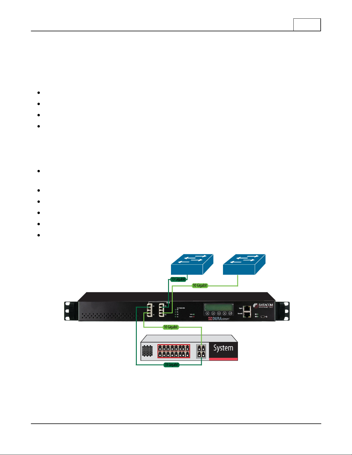
2.5 Technical Brief
DS-1010 is Datacom Systems' 10Gbps intelligent external Active Bypass Switch. The external active
bypass enables plug and play connectivity, includes an auto heartbeat and requires no additional drivers to
be installed on any connected appliance. DS-1010 consists of 1 segment which can support one network
segment and one appliance which provides these features:
1 segment 10Gb active bypass switch
Supports Fiber Multi Mode and Fiber Single Mode
Comprehensive management tools:
Secure Web management Interface (SSL),
o
SNMP
o
CLI by serial console
o
SSH
Different Heartbeat Modes that monitor appliance system health without appliance driver, including:
Internal Loop-back Heartbeat Frame Mode, and Link Status Mode
13
Email Notification for appliance status changes
Power Outage Network Bypass Protection
Field Programmability over Ethernet or Serial Console Port
Syslog support
TACACS+ authentication server
Figure 1. Connectivity example, DS-1010 can connect to 1 network segment
© 2010 Datacom Systems Inc
DURAstream™
Page 13

14
3 Hardware Interface
Figure 2. Front Panel of DS-1010
3.1 Device Management
LCD display to show system name and firmware version
Hardware Interface
Ethernet Management Port
Serial Console Port via Serial Console Cable
LED Power Indicators and LED Link Indicators
3.2 Port LED Interface
Figure 3. Front Panel Segment of DS-1010
10Gigabit N1 and N2 Ports which connect to an ingress network and egress network
10Gigabit A1 and A2 Ports which connect to a network appliance (i.e., IDS, UTM or Firewall)
Link/Active LEDs for 10Gigabit Ports — Link status of the port. Green LED ON signifies link is stable.
Blinking LED signifies there is traffic on that port.
Inline LED — ON for Inline state or OFF for Bypass state
Bypass LED — OFF for Inline state or ON for Bypass state
3.3 LCD Interface
The LCD displays the DURAstream™ 10G firmware version. The < and > keys and up arrow and down
are reserved for future use.
DURAstream™
© 2010 Datacom Systems Inc
Page 14

Theory of Operation
4 Theory of Operation
Modules:
The single mode or multi-mode optical module installed at the factory in each Bypass Switch has 4 ports.
The top two ports are used to connect network devices, these are the network ports and the bottom two
ports of the module direct traffic through the inline appliance, these are the appliance ports. Heartbeat
packets flow between the bottom ports to ensure the appliance is working properly. Heartbeat packets are
not passed beyond the bottom ports.
An inline appliance is connected on the single module using the following diagram:
15
Figure 5. DS-1010 Bypass Switching Mode and Active Switching Mode
Ports are designated as Appliance or Network Ports as shown below:
Figure 6. Network and Appliance Ports
© 2010 Datacom Systems Inc
DURAstream™
Page 15

16
4.1 Operation Modes
DS-1010 has four Operation Modes with Mode 0 being the default Operation Mode:
Mode 0: Normal Active Bypass
If DS-1010 receives heartbeat signals within the TIMEOUT time period, the switching mode
remains or is changed to Active Switching Mode. If DS-1010 does not receive heartbeat signals
within the TIMEOUT time period, it will change to or remain in Bypass Switching Mode. By default
(without any heartbeat), DS-1010 will remain in Bypass Switching mode.
Mode 1: Normal Active Inline
If DS-1010 receives heartbeat signals within the TIMEOUT time period, the switching mode
remains or is changed to Bypass Switching Mode. If DS-1010 does not receive heartbeat signals
within the TIMEOUT time period, it will change to or remain in Active Switching Mode. By default
(without any heartbeat), DS-1010 will remain in Active Switching mode.
Mode 2: Manual Active Inline
DS-1010 is always in Active Switching Mode.
Mode 4: Manual Active Bypass
Theory of Operation
DS-1010 is always in Bypass Switching Mode.
Mode 5: Manual Passive Bypass
DS-1010 is in passive bypass, where the optical switch is close in bypass mode.
DURAstream™
© 2010 Datacom Systems Inc
Page 16

Theory of Operation
4.1.1 Normal Active Bypass
Traffic will flow between the network and appliance ports as shown in the following diagram. If heartbeat
signals are not received within the timeout period, traffic will be routed between N1 and N2. Ports A1 and
A2 will be bypassed. Heartbeat packets will continue to be sent out the Appliance port. This allows the
module to automatically route traffic back through the appliance once it is repaired, or placed back into
service.
17
Figure 7. Normal Active Bypass
Figure 8. Normal Active Bypass Device Failure
© 2010 Datacom Systems Inc
DURAstream™
Page 17

18
Theory of Operation
4.1.2 Normal Active Inline
This setting allows traffic to flow between N1 and N2 while heartbeats continue to flow between A1 and
A2. Loss of heartbeats will direct traffic from N1 to A1 and N2 to A2. This mode may be used to make
sure the heartbeat is flowing through the appliance, while network traffic is not flowing through the
appliance.
Figure 9. Normal Active Inline
Figure 10. Normal Active Inline Heartbeat is Blocked
DURAstream™
© 2010 Datacom Systems Inc
Page 18

Theory of Operation
4.1.3 Manual Active Inline
Traffic flows from N1 to A1 and N2 to A2 until changed. No heartbeat packets are sent.
19
Figure 11. Manual Active Inline
4.1.4 Manual Active Bypass
Traffic flows between N1 and N2. No heartbeat packets are sent, and the device will remain in this mode
until changed.
© 2010 Datacom Systems Inc
Figure 12. Manual Active Bypass
DURAstream™
Page 19

20
Theory of Operation
4.1.5 Manual Passive Bypass
This mode forces connectivity directly between N1 and N2. If the Bypass Switch loses power from both of
its redundant power supplies, the mode will automatically occur, to maintain the network link. Note that
switching to the mode will cause a brief interruption of the network link, which may force routing and link
protocol algorithms to recalculate and renegotiate. This may cause link downtime.
Figure 13. Manual Passive Bypass
DURAstream™
© 2010 Datacom Systems Inc
Page 20

Theory of Operation
4.2 Heartbeat (Hb)
DS-1010 can monitor the continual health of the appliance by sending and receiving Heartbeat (Hb) pulses.
This functionality ensures the real-time safety and accuracy of the data stream. Heartbeat frames are
generally configured to be sent from DS-1010 on one appliance port and received on the other under a set
time limit defined by a customer configured TIMEOUT value. For more information on TIMEOUT value,
see section '<variable> List for CLI .'
DS-1010 provides various heartbeat modes to correspond with different appliance configurations including:
Heartbeat Mode 1: Internal Heartbeat Frame Loop-back Mode:
In Heartbeat Mode 1, the heartbeat signal is a user programmable Ethernet “Heartbeat Frame” and
is generated by DS-1010 itself. The Heartbeat frames are sent out from DS-1010 Ethernet Port A1
every 100ms, and DS-1010 Ethernet Port A2 expects to receive the same Heartbeat Frame from
the appliance. Heartbeat Mode 1 for the DS-1010 is designed for network appliance units that act
as a bridge, like IPS or Firewall. The user needs to make sure the Network appliance is properly
configured so that the device will not filter out the “Heartbeat Frame”.
In heartbeat Mode 1, no driver is needed for Appliance systems.
Heartbeat Mode 3: Link Status Heartbeat Mode:
23
21
In Heartbeat Mode 3, the heartbeat signal acts as the link up status indicator of the DS-1010
Ethernet Port A1 and A2. If any ports of A1 and A2 lose the link, DS-1010 will shut off heartbeat
transmission and activate bypass mode.
4.3 Power Failure Protection
DS-1010 provides two redundant power supply inputs to minimize the chance of power loss or failure.
In addition, DS-1010 continuously monitors the power supply voltage to detect any instance of power
decline or outage. If a power failure is detected, Power Fail Protection Operation is triggered, which
initiates a switch to Bypass Switch. During this no power state, the N1 and N2 ports will physically connect
to create a passive bypass path without any traffic interruption between port N1 and port N2.
© 2010 Datacom Systems Inc
DURAstream™
Page 21

22
Initial Configuration
5 Initial Configuration
IMPORTANT: Prior to initial configuration of the hardware, it is imperative to review the entire
Initial Configuration section before proceeding.
This section explains the considerations and requirements for the initial configuration of the DS-1010 series
by a Command Line Interface (CLI) with a management PC using a terminal emulation application
connected with the provided Console Cable (DB9 to RJ45) through the serial CONSOLE RJ45 port.
5.1 Command Line Interface (CLI)
The Command Line Interface (CLI ) is used to set IP address (default 192.168.0.111), Subnet Mask
(default 255.255.255.0) and default Gateway (default 192.168.0.1) and other options as detailed in the
'Basic Command Set ' and 'Serial Port Configuration (RJ45) ' sections.
5.1.1 Basic Functionality
Window Size Functionality: The CLI window has a limited number of character spaces available (24 lines
per screen, 80 characters per line). If more data than can fit is presented, the number of lines is one less and
a “—more—” prompt is shown on the last line.
22 27
Character Handling: Printable characters (ASCII codes 32-126) and non-printable codes noted below:
Non-Printable Character Description
<enter key> Executes command; places command in history buffer
<backspace key> Erases previous character entry; removes history buffer entry
Connectivity/Authentication Functionality: Connectivity to the bypass product is made through the
Management RJ45 or Console RJ45 port and authentication is required.
Base Prompt: This is the text presented to the user logging in to use the CLI (default values shown). All
Usernames and Passwords are case-sensitive.
Enter Username: admin
Enter Password: admin
>
CLI command usage: Only the "admin" account has permission to configure and check system options.
5.1.2 Basic Command Set
There are two basic commands that you need:
1.
cli get | more
2.
cli set <variable> <option>
With the "cli get | more" command, on the left side of the screen, a list of variables are displayed and usually
the right side of the screen shows the <option> that the <variable> can be set. The "cli get | more" command
reduces flooding the screen as opposed to just the "cli get" command.
For example, towards the end of the "cli get" output for the DS-1010 will list the tap settings available. To
set segment B N1 to receive on the tap port, type "cli set tap_b_n1 1" where "tap_b_n1" is the <variable>
and "1" is the <option> for receive.
DURAstream™
© 2010 Datacom Systems Inc
Page 22

Initial Configuration
<variable>
description
<option>
active_hb_cnt
value stores the active heartbeat signal count, segment will
switch to active switch mode only if it receives
“active_hb_cnt” number for a consecutive heartbeat.
default: 1
1-10
bypass_hb_cnt
value stores the bypass heartbeat signal count, segment
will switch to bypass switch mode only if it loses
“bypass_hb_cnt” heartbeat signal number.
default: 1
1-10
current_ip
current ip address for management port.
dhcp
dhcp client enable/disable, setting option to dhcp will
enable dhcp client on Management Port, setting option to
static will disable dhcp client on Management Port.
default: dhcp active
dns
dns server ip address.
dns2
2ND dns server ip address.
domain
domain name for local host.
default: local
email
setting option value to 1 will enable mail notification
feature.
default: 1
email_from
email from field for email report.
email_password
email account password.
email_security
setting option to 1 will enable email security feature.
default: 1
email_server
smtp server address for email report.
email_subject
email report subject.
email_to
email recipient lists.
email_username
email account user name.
To view specifically what <variable> has what setting in it, type "cli get <variable>."
For example, you want to know if SNMP is enabled, type "cli get snmp." An output will be displayed
showing what SNMP is set to; in this case, it will be either 0 (disabled) or 1 (enabled).
23
A description of each <variable> and their <options> follows in the '<variable> List for CLI ' table.
23
5.1.3 <variable> List for CLI
DS-1010 <variable> <option> list for CLI get/set command.
© 2010 Datacom Systems Inc
DURAstream™
Page 23

24
<variable>
description
<option>
force
configure force (debug) mode for each I/O unit:
default is 0. Force (debug) mode is disabled.
Setting option to value 2 will force segment to Active
switch mode.
Setting option to value 4 will force segment to Bypass
Switch mode.
default: 0
gw
gateway ip address.
default: 192.168.0.1
hb_mode
configure the heartbeat mode for DS-1010 bypass unit:
hb_mode 1, system is generating the heartbeat.
hb_mode 3, the system activates bypass depending
on link detection on the appliance side.
default: 1
host
hostname for DS-1010.
default: datacom
https
https server allows:
a value 0 disables the secure WEB Management
interface.
a value 1 enables access to secure WEB Management
interface.
default: 1
ip
static IP address for Management Port.
default: 192.168.0.111
lfd
1 – enabled, the system will detect and activate the lfd
0 – disabled, the system will not detect lfd
default: 1
mac
shows mac address for the Management Ethernet Port.
read only
mask
subnet mask for Management Port.
default: 255.255.255.0
ntp
ntp service is enabled
0 = disable,
1 = enable
op_mode
configure default operation mode for DS-1010 bypass
unit:
0 – Normal Active Bypass. If the heartbeat is
received the system will be inline.
1 – Normal Active Inline. If the heartbeat is received
the system will be in bypass.
2 – Manual Active Inline.
4 – Manual Active Bypass.
5 – Manual Passive Bypass. The bypass switch will
be closed, in bypass mode.
default: 0
password
administrator password.
default: admin
Initial Configuration
DURAstream™
© 2010 Datacom Systems Inc
Page 24

Initial Configuration
<variable>
description
<option>
snmp
snmp function allows:
value 1 enables snmp function.
value 0 disables snmp function.
default: 1
snmp_community
snmp_community name
datacomc
snmp_destination
snmp_destination name
localhost
state
show state of Datacom bypass unit:
0 – bypass switch state.
1 – active/Inline switch state.
read only
syslog
syslog service is enabled
0 = disable,
1 = enable
syslog_host
host name
syslog_port
syslog port number
default: 514
tacacs
enable tacacs service
0 = disable,
1 = enable
tacacs_encryption
enable tacacs encryption
0 = disable,
1 = enable
tacacs_protocol
tacacs_secret
define the tacacs+ secret
tacacs_server
ip address of tacacs+ server
tacacs_service
timeout
timeout values for DS-1010 bypass unit, each timeout unit
is 100ms, timeout range is 100ms to 255ms.
in default bypass operation mode, if the unit does not
detect a heartbeat frame within the set timeout time value,
the segment will switch from active to bypass.
1-255
tz
time zone 3 letter definition
default: PST
username
administrator account name: datacom login:
default: admin
web_theme
web themes enable.
0 = disable,
1 = enable
25
© 2010 Datacom Systems Inc
DURAstream™
Page 25

26
5.1.4 Command Line Interface Usage
Only the “admin” account has permission to configure and check the system <variables>.
Initial Configuration
Figure 14. "CLI get" output
To dump values for all <variables>, “cli get | more”
To display a value for individual <variable>, “cli get <variable>”
For example, “cli get timeout” will display timeout value in decimal form.
To set a value for individual <variable>, “cli set <variable> <option>
For example, “cli set timeout 20” will set timeout value to 20.
DURAstream™
© 2010 Datacom Systems Inc
Page 26

Initial Configuration
5.2 SERIAL Port Configuration (RJ45)
Note: Use the Console Cable (DB9 to RJ45) through the CONSOLE RJ45 port for initial configuration of
the hardware. Once DS-1010 series connection is made, open the terminal emulation application and create
a connection with settings that fit your needs as described in the 'HyperTerminal ' section.
5.2.1 HyperTerminal
Any freely available terminal emulator may be utilized, but please take note of the specific Microsoft
HyperTerminal settings in the following example, if an alternate terminal emulator is used.
HyperTerminal (terminal emulator) enter:
115,200 bits per second; 8 data bits; Parity none; 1 stop bit; Flow control none
27
27
After completing review of the Command Line Interface (CLI) section, detailed IP Address
configuration can be found in the IP Address Configuration section.
22
27
5.2.2 IP Address Configuration
All DS-1010 series units are shipped with a factory default configuration as follows:
IP Address:192.168.0.111; Subnet Mask: 255.255.255.0; default Gateway: 192.168.0.1
IMPORTANT: If you expect to remotely connect to the DS-1010 series, you must change the IP Address,
Subnet Mask and default Gateway to match your Local Area Network.
The IP address can be configured via a serial connection with either Microsoft's HyperTerminal application
(available on most Windows PCs) or an open source free software terminal emulator for MS-Windows.
Step 1. Using a supplied AC switching adapter and line cord, plug the DS-1010 into an AC power source.
Step 2. Connect your PC and DS-1010 using the provided Datacom Systems CONSOLE cable. Create a
HyperTerminal (terminal emulator) COM port (115,200, 8, None, 1, None) serial link.
Step 3. You are now connected to your DS-1010 series. All Usernames and passwords are case-sensitive.
datacom login: admin (default value) <enter>
Password: admin (default value) <enter>
Step 4. Set IP, MASK and GATEWAY at the ~ $ prompt as follows:
cli set ip xxx.xxx.xxx.xxx <enter>
cli set mask xxx.xxx.xxx.xxx <enter>
cli set gw xxx.xxx.xxx.xxx <enter>
Step 5. Close HyperTerminal and disconnect the CONSOLE serial cable.
Step 6. Install the DS-1010 series in your chosen network location.
© 2010 Datacom Systems Inc
DURAstream™
Page 27

28
MANAGEMENT Port Configuration (RJ45)
6 MANAGEMENT Port Configuration (RJ45)
DS-1010 users can log into and manage the DS-1010 through a Command Line Interface Environment via
the Console Port (serial terminal emulator) or via the Management Port (SSH remote shell emulator)
through a Web browser secure “HTTPS” connection.
Once DS-1010 series connection is made to the MANAGEMENT RJ45 port, open the terminal emulation
application and create a connection with settings that fit your needs:
The factory default DS-1010 series IP Address, Subnet Mask and default Gateway are as follows:
IP Address: 192.168.0.111; Subnet Mask: 255.255.255.0; default Gateway: 192.168.0.1
6.1 SSH Setting
DS-1010 SSH server uses standard port 22.
6.2 User Account
The “admin” account allows system administrators to configure programmable options and monitor unit
status.
6.3 Password
The default Password for the admin account is “admin”. The password can be changed using the CLI
command.
6.4 SNMP
DS-1010 supports SNMP traps on predefined events.
6.4.1 Support
The Events that will be triggering traps are as follows:
SNMP trap LFD (Link Fault Detection), will be generated following detection of a network port going
down. The usual case will be that first a network port trap will be received following by LFD.
SNMP trap on link up or down – when any of the links (network link or appliance link) change state (up
or down) a trap will be generated, specifying the link name and the link status (up or down)
SNMP TRAP- on system state change (bypass or Inline). In this mode the trap will provide the state
(bypass or Inline) with the op_mode, defining the operation mode of the system:
o
[0]"Normal Active Bypass",
o
[1]”Normal Active Inline”,
o
[2]”Always Active Inline”,
o
[4]"Always Active Bypass",
o
[5]"Manual Passive Bypass"
SNMP TRAP- For Cold or Warm power up (when device is powered up)
DURAstream™
© 2010 Datacom Systems Inc
Page 28

MANAGEMENT Port Configuration (RJ45)
snmp
Defalut <option> is 0 (SNMP: 0=DISABLED, 1=ENABLED)
snmp_community
default <option> is -- datacomc
snmp_destination
default <option> is -- localhost
snmp_ifalias
default <option> is – datacomif
tacacs_enabled
1
tacacs_server
192.168.3.55 (this is the TACACS+ server IP address)
tacacs_encrypt
0
tacacs_secret
None
tacacs_service
all
tacacs_protocol
all
syslog
default value = 0 (Syslog service: 0=DISABLED, 1=ENABLED
syslog_host
default value = localhost
syslog_ident
default value = datacom
syslog_port
default value = 514
6.4.2 CLI Setup
6.5 TACACS+ Setup
Configuring TACACS+ from the CLI:
~ $ cli set tacacs_server <IP>
~ $ cli tacacs_enabled 1
~ $ cli get – to show all the TACACS+ options:
29
6.6 NTP Definitions
ntp 0 (NTP service: 0=DISABLED, 1=ENABLED)
ntp_server default value is: us.pool.ntp.org
6.7 SYSLOG Definitions
© 2010 Datacom Systems Inc
DURAstream™
Page 29

30
Figure 15. Certificate Error Page
Figure 15. Certificate Error Page,
shows the first page that appears on the
web browser after entering the URL.
Currently, DS-1010’s website security
certification is in the process of being
approved. You will need to accept the
fact that the certificate has not been
approved to continue. Therefore, the
user needs to click “Continue to this
website (not recommended)” to go to
the login page
Figure 16. Login, shows the User Login
Page where the default user name is “admin”
and “admin” is the password
Figure 16. Login
Secure Web Management
7 Secure Web Management
DS-1010 provides a Secure Web Management Interface for system administrators to manage and monitor
DS-1010 via any web browser. To access the management web page, the Ethernet Management port
needs to be connected to the local network or host computer.The URL to access the Web Management
interface, “https://<Mgnt Port IP>”, can be found though “CLI interface” or LCD interface. The default
Management Port IP is 192.168.0.111.
7.1 Login
DURAstream™
© 2010 Datacom Systems Inc
Page 30

Secure Web Management
Figure 17. DS-1010 Status Page
Figure 17. DS-1010 Status Page, shows the
Status page provides the system information
including: revision information, power supply
status, unit link status and the operation mode.
Figure 18. Bypass Module Setting, shows
the options and allows the user to set and
tune them according to the site requirements.
Figure 18. Bypass Module Setting
Figure 19. Management Port
Figure 19. Management Port, shows the
Management Port options which can configure IP
settings of the management port.
7.2 Status
7.3 Bypass Module
31
7.4 Management Port
© 2010 Datacom Systems Inc
DURAstream™
Page 31

32
Figure 20. eMail Notifications
Figure 20. eMail Notifications, shows the email
notification options which need to be filled
properly by the system administrator to enable or
disable the email notification function and
configures the email servers and accounts.
Figure 21. SNMP Settings, shows the
SNMP options setting which enables or
disables the SNMP Trap function and
configures the SNMP destination IP and
SNMPv2 community name.
Figure 21. SNMP Settings
Figure
22. NTP Settings
Figure 22. NTP Settings, shows the Network
Time Protocol (NTP) options setting which
enables or disables synchronizing the computer
system clock over packet-switched, variablelatency data networks. NTP uses UDP on port
123 as its transport layer. It is designed
particularly to resist the effects of variable latency
by using a jitter buffer.
Secure Web Management
7.5 eMail Notifications
DS-1010 provides an Email Notifications function which initiates an email notification upon switching mode
of an I/O segment. The mail server and email account settings can be configured through the Web
management or CLI interface.
7.6 SNMP Settings
DS-1010 provides SNMP Trap function which can send messages to a destination IP when the I/O
segment status or Power Supply status is changed.
7.7 NTP Settings
DURAstream™
© 2010 Datacom Systems Inc
Page 32

Secure Web Management
Figure 23. Time Settings, shows the screen
for time zone setting.
Figure 23. Time Settings
Figure 24. Backup/Restore Setting
Figure 24. Backup/Restore Setting, shows the
back up and restore options which can restore the
DS-1010 to default settings.
Figure 25. Firmware Update, shows
firmware update options which enable
firmware update of DS-1010.
Figure 25. Firmware Update
Figure 26. Log Settings
Figure 26. Log Settings, shows the Log Setting
options which enables or disables forwarding log
messages in an Internet Protocol (IP) computer
network. It allows separation of the software that
generates log messages from the system that stores
the messages.
7.8 Time Settings
7.9 Backup/Restore
33
7.10 Firmware Update
7.11 Log Settings
© 2010 Datacom Systems Inc
DURAstream™
Page 33

34
Figure 27. Reboot, shows Reboot which
allows Restart of the appliance when you
change the time settings or when directed to
restart by technical support.
Figure 27. Reboot
Figure 28. User Account Settings
Figure 28. User Account Settings, shows the
User Account options which allows for the change
of a user name and password via the WEB
management page.
Figure 29. TACACS+, shows the Terminal
Access Controller Access-Control System
Plus (TACACS+) which enables or disables
the protocol which provides access control
for routers, network access servers and other
networked computing devices via one or
more centralized servers. TACACS+
provides separate authentication,
authorization and accounting services.
Figure 29. TACACS+
7.12 Reboot
7.13 Users
Secure Web Management
7.14 TACACS+
DURAstream™
© 2010 Datacom Systems Inc
Page 34

Appendix 1 Heartbeat frame format
8 Appendix 1 Heartbeat frame format
DS-1010 Heartbeat frame format.
Total Frame Size: 128 Bytes ( including CRC Checksum)
Byte : 0 - 11 byte ( are Destination and Source Mac address )
==============================================================
Destination MAC : 00:0C:BD:00:00:FF
Source MAC : 00:0C:BD:00:00:<Port Number>
Byte : 12 - 13 byte ( are Ether Frame Type : 0x8000)
==============================================================
EtherFrame : 0x80 0x00
Byte : 14 - 63 byte ( pattern count from 0x00 - 0x3F)
==============================================================
Payload or Data : 0x00 0x01 0x02 0x03 0x04 0x05 .. 0x3F
35
Byte : 64 - 123 byte ( pattern = 0x55 )
==============================================================
Payload or Data : 0x55 0x55 … 0x55
Byte : 123 - 127 byte ( CRC Checksum field)
=============================================================
This field is byte machine generated.
<= CRC checksum
© 2010 Datacom Systems Inc
DURAstream™
Page 35

36
DB9 Connector
Pin 1, Pin 4, Pin 6 - are shorted together
Pin 2 - Green Striped wire
Pin 3 - Solid Green wire
Pin 5 - Solid Blue/ Blue Stripe wire
Pin 7, Pin 8 - Short
Pin 9 - No Connect
Other 2 Sets of Wires: Orange/Orange Stripe and Brown/Brown Stripe
Solid Orange and Brown Stripe should be connected together
Stripe Orange and Solid Brown should be connected together
9 Appendix 2 Console-Cable Drawing
Blue Elmech Console-Cable Drawing
Appendix 2 Console-Cable Drawing
DB9 Connector Front View
DB9 Connector Pin Description
DURAstream™
© 2010 Datacom Systems Inc
Page 36

Appendix 2 Console-Cable Drawing
CAT5e Cable Wire Colors Top to Bottom
Orange/White Stripe wire
Solid Orange wire
Green/White Stripe wire
Solid Blue wire
Blue/White Stripe wire
Solid Green wire
Brown/White Stripe wire
Solid Brown wire
CAT5e Cable Wire Colors Top to Bottom
Solid Brown wire
Brown/White Stripe wire
Solid Green wire
Blue/White Stripe wire
Solid Blue wire
Green/White Stripe wire
Solid Orange wire
Orange/White Stripe wire
37
CAT5e Cable Wire Colors (Top View)
CAT5e Cable Wire Colors (Bottom View)
© 2010 Datacom Systems Inc
DURAstream™
Page 37

38
Customer Service
10 Customer Service
This USERguide was written to help you get to know your new DURAstream Bypass Switch quickly
and easily. We would welcome any comments or suggestions you may have regarding this USERguide.
Please send your remarks and recommendations via mail, telephone, facsimile, or Internet E-mail.
Datacom Customer Service is available via telephone, facsimile, and Internet E-mail. Outside of support
hours, please leave a voice message and our Customer Service Staff will return your call as soon as
possible. You may also find assistance at our website: http://www.datacomsystems.com.
Tel: (315) 463-9541
Fax: (315) 463-9557
E-mail:support@datacomsystems.com
Web: www.datacomsystems.com
10.1 Internet
You can obtain additional information about Datacom Systems, Inc. and its products and services from the
Internet at: http://www.datacomsystems.com
10.2 Warranty
Datacom Systems, Inc. (DSI) warrants that the hardware which it supplies will be free from significant
defects in materials and workmanship for a period of two years from the date of delivery (Warranty
Period), under normal use and conditions. In the event of any such defect, you can return an item of
defective hardware, freight prepaid, to DSI during the Warranty Period, and DSI will repair or replace the
defective equipment and return it to you, freight prepaid. If DSI determines that the equipment is not
defective, it will return it to you, freight collect. DSI shall have no responsibility for any deficiency resulting
from accidents, misuse, modifications, power disturbances (including use of a power supply not specified by
DSI), or various other forms of disaster, e.g., earthquakes, floods, etc.
PLEASE DO NOT ATTEMPT TO RETURN ANY ITEM PRIOR TO RECEIVING A RETURN
MATERIAL AUTHORIZATION (RMA) NUMBER FROM DATACOM CUSTOMER SERVICE AT
(315) 463-9541 or support@datacomsystems.com
10.3 Limits of Liability
The warranties set forth above are exclusive and in lieu of all other warranties. Datacom Systems, Inc.
(DSI) makes no other warranties, expressed or implied, and DSI expressly disclaims all other warranties,
including but not limited to implied warranties of merchantability and fitness for a particular purpose.
Moreover, the provisions set forth above state DSI’s entire responsibility and your sole and exclusive
remedy with respect to any breach of warranty or contract.
No liability for consequential damages. Under no circumstances and under no theory of Liability shall DSI
be liable for costs of procurement of substitute products or services, lost profits, lost savings, loss of
information or data, or any other special, indirect, consequential or incidental damages, arising in any way
out of the sale of, use of, or inability to use, any DSI product or service, even if DSI has been advised of the
possibility of such damages.
DURAstream™
© 2010 Datacom Systems Inc
Page 38

This page intentionally left blank
© 2010 Datacom Systems Inc
Page 39

Datacom Systems Inc.
9 Adler Drive • East Syracuse, NY 13057
TEL: (315) 463-9541 • FAX: (315) 463-9557
http://www.datacomsystems.com
Datacom Systems Inc
Access Your Network
TM
 Loading...