

Page 1
DS-1404, DS-1406, DS-2408
Bypass Switches
April 2016
© 2016 Datacom Systems Inc.
FASTstart Guide
Page 2

2
DURAstream™ DS-1404, DS-1406, DS-2408 FASTstart Guide
Table of Contents
1 Terms of Use ............................................................................................................................................... 5
1.1 Copyright ......................................................................................................................................................... 5
1.2 License Agreement ........................................................................................................................................ 5
1.3 Proprietary Notice .......................................................................................................................................... 5
1.4 Trademark Attribution .................................................................................................................................... 5
1.5 Certifications and Marks ................................................................................................................................. 5
1.6 Safety Notices and Warnings .......................................................................................................................... 6
2 Overview .................................................................................................................................................... 7
2.1 What Shipped? ............................................................................................................................................... 8
2.2 Specifications .................................................................................................................................................. 8
2.3 Supported SFP Transceivers ........................................................................................................................... 9
2.4 Rack Installation ............................................................................................................................................. 9
2.5 Front - Port Types ......................................................................................................................................... 10
2.6 Front - Power & Status Indicators ................................................................................................................ 13
2.7 Rear - Power Ports ........................................................................................................................................ 13
2.8 Rear — Unit Identifiers ................................................................................................................................. 14
3 Network IP Address Configuration ................................................................................................................ 15
3.1 Default Settings ............................................................................................................................................ 15
3.2 Setting up the DURAstream™ for Management Port Access ...................................................................... 16
4 Management Connection .......................................................................................................................... 18
4.1 Setup ............................................................................................................................................................. 18
4.2 Connecting via Telnet .................................................................................................................................... 19
5 Bypass Terminology Explanation ............................................................................................................... 21
5.1 Overview ....................................................................................................................................................... 21
5.2 Heartbeat Frequency .................................................................................................................................... 21
5.3 Heartbeat Expiration ..................................................................................................................................... 22
5.4 Heartbeat Fail Count ..................................................................................................................................... 23
5.5 Heartbeat Reactivation Count ...................................................................................................................... 24
5.6 Heartbeat Direction ...................................................................................................................................... 25
5.7 Heartbeat Packet Type .................................................................................................................................. 26
5.8 System Bypass Modes ................................................................................................................................... 27
5.8.1 Normal ................................................................................................................................................... 27
5.8.2 Normal High Availability ........................................................................................................................ 28
5.8.3 Manual Inline ........................................................................................................................................ 32
Page 3

3
DURAstream™ DS-1404, DS-1406, DS-2408 FASTstart Guide
5.8.4 Manual Bypass ...................................................................................................................................... 33
5.8.5 Passive Bypass ....................................................................................................................................... 34
6 Command List ........................................................................................................................................... 35
6.1 Bypass Commands ........................................................................................................................................ 35
6.1.1 Bypass Get Info...................................................................................................................................... 35
6.1.2 Bypass Get Info Reset ............................................................................................................................ 35
6.1.3 Bypass Set Direction .............................................................................................................................. 35
6.1.4 Bypass Set Expire ................................................................................................................................... 36
6.1.5 Bypass Set Fail ....................................................................................................................................... 36
6.1.6 Bypass Set Frequency ............................................................................................................................ 36
6.1.7 Bypass Set Mode ................................................................................................................................... 37
6.1.8 Bypass Set Packet .................................................................................................................................. 37
6.1.9 Bypass Set Reactivate ............................................................................................................................ 37
6.2 Email Notification Commands ....................................................................................................................... 38
6.2.1 Email Get Settings ................................................................................................................................. 38
6.2.2 Email Send Test ..................................................................................................................................... 38
6.2.3 Email Set Password ............................................................................................................................... 38
6.2.4 Email Set Destination ............................................................................................................................ 39
6.2.5 Email Set Source .................................................................................................................................... 39
6.2.6 Email Set Server .................................................................................................................................... 39
6.2.7 Email Set Trigger ................................................................................................................................... 40
6.3 Management Port Commands ...................................................................................................................... 40
6.3.1 Management Get Info ........................................................................................................................... 40
6.3.2 Management Reset ............................................................................................................................... 41
6.3.1 Management Set CLI Timeout ............................................................................................................... 41
6.3.2 Management Set Daemon CLI .............................................................................................................. 41
6.3.3 Management Set Daemon Shell ............................................................................................................ 41
6.3.4 Management Set Daemon NTPD .......................................................................................................... 42
6.3.1 Management Set DHCP ......................................................................................................................... 42
6.3.2 Management Set DNS ........................................................................................................................... 42
6.3.3 Management Set IP ............................................................................................................................... 43
6.3.4 Management Set Gateway .................................................................................................................... 43
6.3.5 Management Set Password .................................................................................................................. 43
6.3.6 Management Set Subnet ...................................................................................................................... 43
6.3.7 Management Set TFTPServer ................................................................................................................ 44
6.3.8 Management Set Username ................................................................................................................. 44
6.4 Port Commands ............................................................................................................................................. 44
Page 4

4
DURAstream™ DS-1404, DS-1406, DS-2408 FASTstart Guide
6.4.1 Port Get Info .......................................................................................................................................... 44
6.4.2 Port Get Counter ................................................................................................................................... 45
6.4.3 Port Get Counter Detail ......................................................................................................................... 45
6.4.4 Port Reset Counter ................................................................................................................................ 45
6.4.5 Port Set Media....................................................................................................................................... 46
6.4.6 Port Set Speed ....................................................................................................................................... 46
6.5 Switch Commands ......................................................................................................................................... 47
6.5.1 Switch Restart ....................................................................................................................................... 47
6.5.2 Reset To Factory Defaults ..................................................................................................................... 47
6.5.3 Update System Firmware ...................................................................................................................... 47
6.6 System Commands ........................................................................................................................................ 48
6.6.1 System Get Info ..................................................................................................................................... 48
6.6.1 System Reset Logfile ............................................................................................................................. 48
6.6.2 System Send Logfile .............................................................................................................................. 49
6.6.3 System Set Name .................................................................................................................................. 49
6.6.4 System Set NTPDserver ......................................................................................................................... 50
6.6.5 System Set Time .................................................................................................................................... 50
6.6.6 System Set Zone .................................................................................................................................... 50
7 Configuration Examples ............................................................................................................................ 51
7.1 Single Copper Appliance for a 1G Fiber Link. ................................................................................................ 51
8 Customer Service ...................................................................................................................................... 54
Page 5

5
DURAstream™ DS-1404, DS-1406, DS-2408 FASTstart Guide
1 Terms of Use
The following terms and conditions relate to the use of this document. Please note
that Datacom Systems Inc. reserves the right, at its entire discretion, to change,
modify, add, or remove portions of these Terms of Use at any time. Please read the
Terms of Use carefully as your use of this document is subject to the Terms of Use
stipulated herein.
1.1 Copyright
Copyright ©2016 by Datacom Systems, Inc. All rights reserved. Printed in the
United States of America. No part of this publication may be reproduced, stored in a
retrieval system, or transmitted, in any form or by any means, electronic, mechanical,
photocopying, recording, or otherwise, without the prior written permission of
Datacom Systems, Inc.
1.2 License Agreement
Notice to All Users: By using Datacom Systems, Inc. products, you agree to the
terms set forth. No licenses, express or implied, are granted with respect to the
technology described and Datacom Systems, Inc. retains all rights with respect to the
technology described herein. If applicable, you may return the product to the place of
purchase for a full refund.
1.3 Proprietary Notice
This document contains proprietary information about the DS-1404, DS-1406, and
DS-2408 Bypass Switches Command Line Interface (CLI) and is not to be disclosed
or used except as authorized by written contract with Datacom Systems, Inc.
1.4 Trademark Attribution
Access Your Network™, DURAstream™, SINGLEstream™, and VERSAstream™,
are trademarks of Datacom Systems, Inc. All other registered and unregistered
trademarks are the sole property of their respective owners. All specifications may be
changed without notice.
1.5 Certifications and Marks
For information regarding certifications and marks, please refer to the product info
section of our website at http://www.datacomsystems.com
Datacom Systems Inc. 2016
Page 6

6
DURAstream™ DS-1404, DS-1406, DS-2408 FASTstart Guide
1.6 Safety Notices and Warnings
These explanatory labels are included in this information for the user in
accordance with the requirements of IEC 60825.1.
WARNING
under all conditions of normal use. Invisible laser radiation may be
emitted from optical port openings when no fiber cable is connected,
avoid exposure to laser radiation and do not stare into open optical
ports.
IMPORTANT: Rack Mount Instructions are included here to call the attention of
installation technicians to pertinent safety and warning issues prior to the installation of the
product as follows:
A. Elevated Operating Ambient — If installed in a closed or multi-unit rack assembly, the
operating ambient temperature of the rack environment may be greater than room
ambient. Therefore, consideration should be given to installing the equipment in an
environment compatible with the maximum ambient temperature specified.
B. Reduced Air Flow — Installation of the equipment in a rack should be such that the
amount of air flow required for safe operation of the equipment is not compromised.
C. Mechanical Loading — Mounting of the equipment in the rack should be such that a
hazardous condition is not achieved due to uneven mechanical loading.
D. Circuit Overloading — Consideration should be given to the connection of the
equipment to the supply circuit and the effect that overloading of the circuits might
have on over-current protection and supply wiring. Appropriate consideration of
equipment nameplate ratings should be used when addressing this concern.
E. Reliable Earthing — Reliable earthing of rack-mounted equipment should be
maintained. Particular attention should be given to supply connections other than direct
connections to the branch circuit (e.g. use of power strips).
:
Class 1 laser and LED product. A class 1 laser is safe
Datacom Systems Inc. 2016
Page 7

7
DURAstream™ DS-1404, DS-1406, DS-2408 FASTstart Guide
2 Overview
This FASTstart Guide for the DS-1404, DS-1406, and DS-2408 Bypass Switches is
intended to provide you with information needed to get your Bypass Switch up and
running. Additional support, documentation and help can be found on the Datacom
Systems website: http://www.datacomsystems.com
The DURAstream™ Bypass Switches provide an easy-to-manage external active bypass
failover for data monitoring of critical 1 or 10 Gigabit fiber network segments. Line rate
throughput and real-time data forwarding hardware protects data and allows critical voice
and data applications to perform uninterrupted and meet high demands for quality and
security. Deployed with an in-line monitoring tool, a DURAstream™ Bypass Switch
creates a comprehensive solution for intrusion prevention.
Like all Datacom Systems Data Access Products, the DURAstream™ Bypass Switches are
compatible with all vendor hardware and can be controlled by a Command Line Interface
(CLI).
Datacom Systems Inc. 2016
Page 8

8
DURAstream™ DS-1404, DS-1406, DS-2408 FASTstart Guide
2.1 What Shipped?
1- DS-1404, DS-1406, or DS-2408 Bypass Switch
2- Switching AC Adapters
1- DRL512-2M-R cable
1- DB9 M/F straight through
2- AC Line Cords
2.2 Specifications
DS-1404 Ports:
Network Ports: Two (2) 10/1G Fiber
Appliance Ports: Two (2) SFP+ (Supports SFP+ SR, LR, LRM, SFP SX, LX, BT)
DS-1406 Ports:
Network Ports: Two (2) 10/1G Fiber
Appliance Ports: Four (4) SFP+ (Supports SFP+ SR, LR, LRM, SFP SX, LX, BT)
DS-2408 Ports:
Network Ports: Four (4) 10/1G Fiber
Appliance Ports: Four (4) SFP+ (Supports SFP+ SR, LR, LRM, SFP SX, LX, BT)
Management Port (front):
RJ45 @ 10/100/1000 Mb Full-Duplex
Serial Port (front):
DB9 @ 115,200 bps; 8 data bits; Parity none; 1 stop bit; Flow control none
Power Requirements:
Maximum Power Consumption: Less than 90 Watts
Individual Power Supply Rating: 100-240V ~50-60Hz 7A MAX.
Dimensions (H x W x D):
1.5 x 8.3 x 12.5 in (3.81 x 21.08 x 31.75 cm)
Weight:
3.75 lbs (1.7 kgs)
Datacom Systems Inc. 2016
Page 9

9
DURAstream™ DS-1404, DS-1406, DS-2408 FASTstart Guide
Model #
Specification
FCLF-8521-3
100BASE-TX, 1000BASE-T
FTLF1318P3BTL
1000BASE-LX
FTLF1319F1GTL
1000BASE-LX
FTLF8519P3BTL
1000BASE-SX Ethernet
FTLX1412D3BCL
10GBASE-LR, 10GBASE-LW
FTLX1471D3BCV
1000BASE-LX, 10GBASE-LR, 10GBASE-LW
FTLX1612M3BCL
10GBASE-ER, 10GBASE-EW, 10GBASE-ER/EW + FEC
FTLX1671D3BCL
10GBASE-ER, 10GBASE-EW
FTLX1811M3
10GBASE-ZR, 10GBASE-ZW
FTLX8511D3
10GBASE-SR, 10GBASE-SW
FTLX8512D3BCL
10GBASE-SR, 10GBASE-SW
FTLX8571D3BCL
10GBASE-SR, 10GBASE-SW
FTLX8571D3BCV
1000BASE-SX, 10GBASE-SR, 10GBASE-SW
Environmental:
Operating Temperature: 32º to 104ºF (0º to 40ºC)
Storage Temperature: -22º to 149ºF (-30º to 65ºC)
Humidity: 5 to 90% non-condensing
Warranty:
Visit http://www.datacomsystems.com/support/warranty-info for more information.
2.3 Supported SFP Transceivers
Datacom Systems supports the following small form-factor pluggable (SFP) transceivers
and enhanced small form-factor pluggable (SFP+) transceivers:
2.4 Rack Installation
Please refer to the rack mount installation guide for the RMC-2C at:
http://www.datacomsystems.com/products/accessories
Datacom Systems Inc. 2016
Page 10
10
DURAstream™ DS-1404, DS-1406, DS-2408 FASTstart Guide
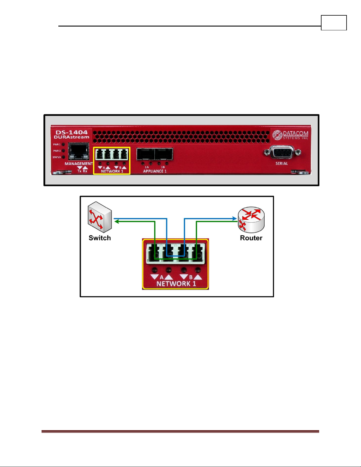
2.5 Front - Port Types
Network Pairs: Network Pairs are connected inline in the same way an appliance would
normally be installed to the network. Network port 1 connects to one endpoint, and
Network port 2 connects to the endpoint on the opposite end of the link. Network Pairs
have a multi-tiered fail-open mechanism that allows them to preserve network connectivity
in the event of an appliance failure, or even a power failure to the DURAstream™.
Datacom Systems Inc. 2016
Page 11
11
DURAstream™ DS-1404, DS-1406, DS-2408 FASTstart Guide
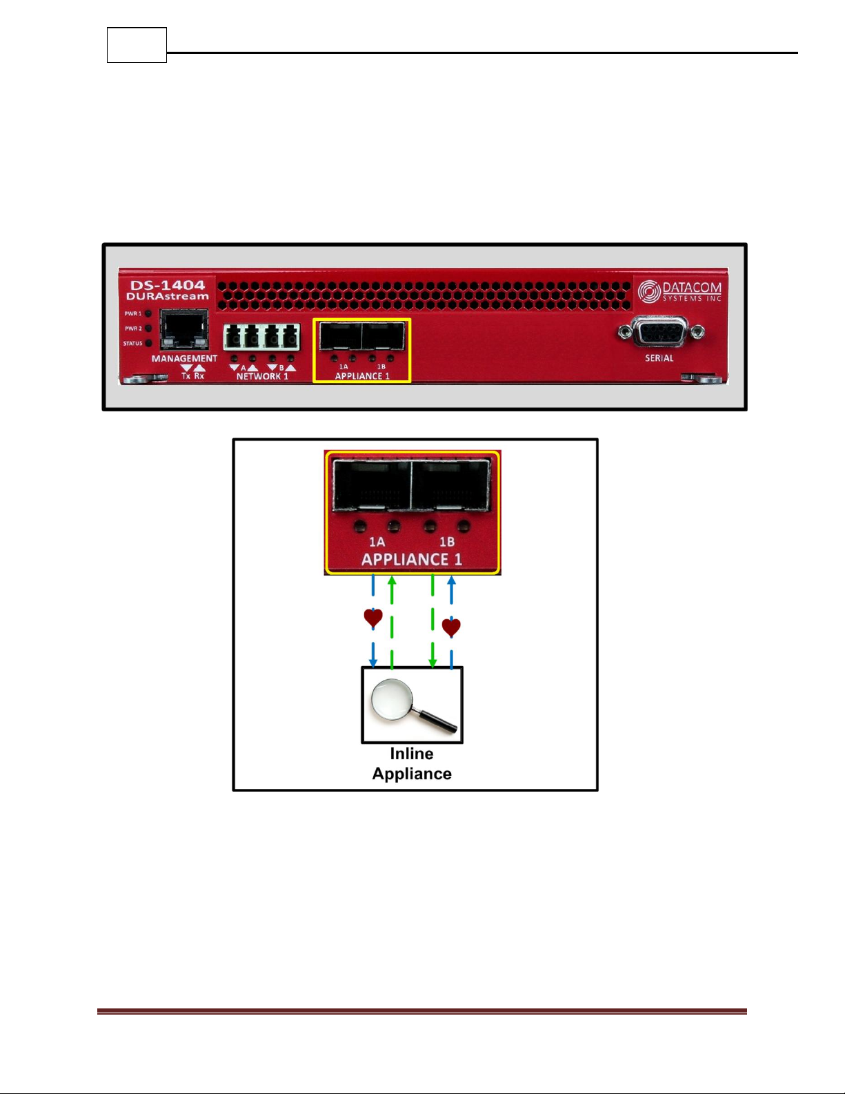
Appliance Pairs: Appliance pairs connect the appliance to the DURAstream™ in the
same way that it would normally connect to a network. Appliance ports provide
connectivity between the network traffic and the appliance. In addition to providing the
appliance with inline network traffic, appliance pairs will also send heartbeat packets to
monitor the health of the appliance. The DURAstream™ uses this information to decide if
the appliance should be inline or cut off from live traffic.
Datacom Systems Inc. 2016
Page 12
12
DURAstream™ DS-1404, DS-1406, DS-2408 FASTstart Guide
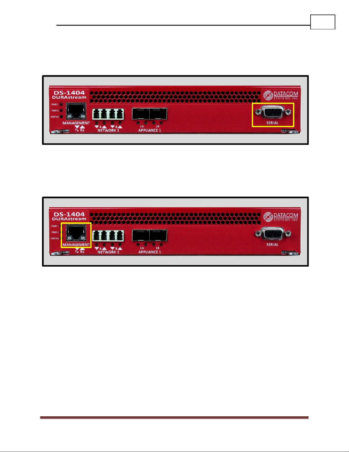
Serial Port: The serial port can be used to connect to the DURAstream™ Bypass Switch
using a DB9 M/F straight through cable. Using a terminal emulator such as Tera Term or
Putty, the serial port may be accessed for login and configuration using the CLI interface.
Management Port: The management port can be used to connect to the DURAstream™
Bypass Switch using a standard copper ethernet RJ-45 cable. Using a terminal emulator
such as Tera Term or Putty, the management may be accessed for login and configuration
using the CLI interface using Telnet.
Datacom Systems Inc. 2016
Page 13
13
DURAstream™ DS-1404, DS-1406, DS-2408 FASTstart Guide
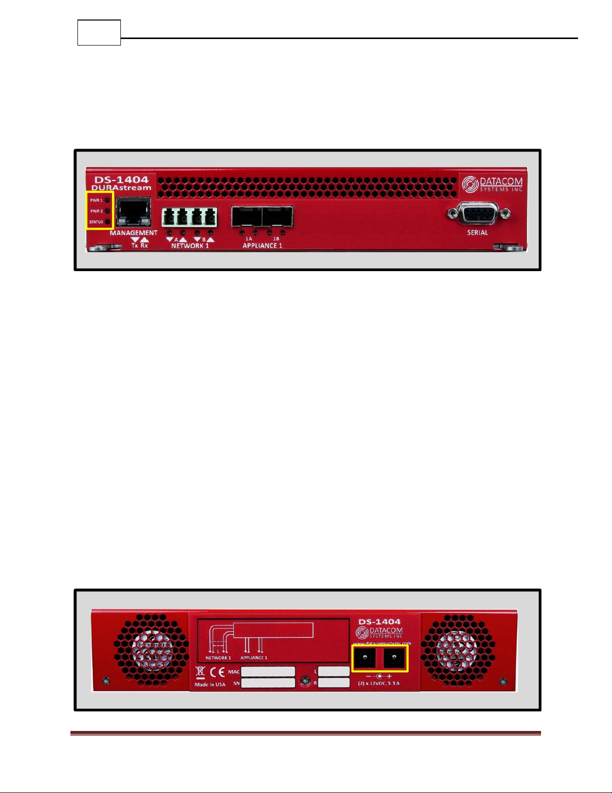
2.6 Front - Power & Status Indicators
On the front panel, the power status of the device can be determined through three
indicators labeled “POWER 1”, “POWER 2”, and “STATUS”.
The LEDs located next to each power label will illuminate green when a power supply is
connected and switched ON.
When the power indicators illuminate red, it indicates that there is either not a power
supply connected, or it is not switched ON.
Although only one power source is required to power the DURAstream™, use of a second
independent power source is strongly recommended to assure maximum link uptime.
The “STATUS” LED indicator flashes green during the boot-up cycle and turns solid
green upon a successful boot sequence indicating the DURAstream™ is operational.
2.7 Rear - Power Ports
Each DURAstream™ has two power ports on the back. These dual redundant power ports
should be connected to power supplies on two separate circuits to ensure maximum link
uptime. These LED indicators function in unison with the “POWER 1”, and “POWER 2”
indicators on the front of the device.
Datacom Systems Inc. 2016
Page 14
14
DURAstream™ DS-1404, DS-1406, DS-2408 FASTstart Guide
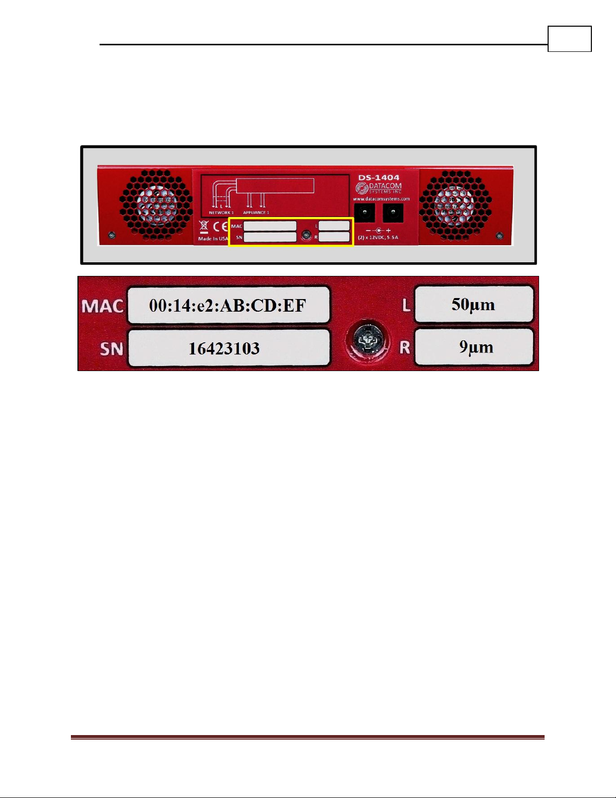
2.8 Rear — Unit Identifiers
Important information such as the MAC address, serial number, and micron specification
of the bypass switch network links can be found on the back of the unit.
MAC: The Media Access Control (MAC) address for the management port for on the
front of the device is printed here. This is a permanent address that will indicate the unique
DURAstream™ ID to the network.
Serial: The serial number is used to identify a specific Datacom product for tracking or
support contract purposes.
L and R: The micron specifications for the Network Pairs are shown here. L stands for
Network Pair 1, R stands for Network Pair 2. It’s important for the micron specification of
the network pair to match the specification of the fiber cables being used, and the fiber
ports on the network endpoints connected to them.
Datacom Systems Inc. 2016
Page 15
15
DURAstream™ DS-1404, DS-1406, DS-2408 FASTstart Guide
Telnet
Port: 23
Serial Terminal Settings
Bits per second: 115200
Data bits: 8
Parity: None
Stop: 1
Flow Control: None
Management Port Settings
IP Address: 192.168.1.1
Subnet Mask: 255.255.0.0
Default Gateway: 192.168.0.1
User Settings
Username: Administrator
Password: admin
3 Network IP Address Configuration
All DURAstream™ Bypass Switches can be accessed and configured through the
management port on the front of the unit. Once set up, this port can be used to access the
device through Telnet.
3.1 Default Settings
All DS-X4XX Bypass Switch series units are shipped with a factory default configuration
as follows:
IMPORTANT: If you expect to remotely connect to the DURAstream™ series, you
must change the IP Address, Subnet Mask and Gateway to match your Local Area
Network.
In order to initially change the IP settings on the management port, you can connect to the
device over the serial port on the front.
Datacom Systems Inc. 2016
Page 16
16
DURAstream™ DS-1404, DS-1406, DS-2408 FASTstart Guide
3.2 Setting up the DURAstream™ for Management Port Access
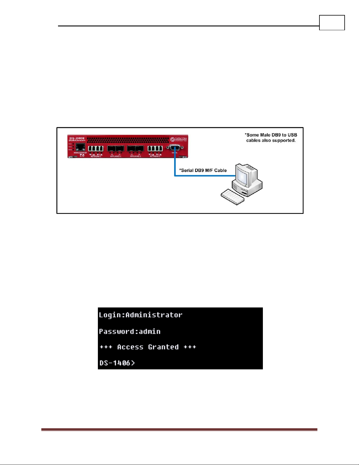
Step 1: First, connect your PC and your DURAstream™ using the provided Datacom
Systems DB9 M/F straight through cable. Connect the DB9 Female pin end to the serial
port on your PC and connect the DB9 Male pin to the serial port on your DURAstream™.
NOTE: For PCs without 9-pin serial ports, check with your product representative for
available sources of a USB RS-232 Serial Adapter.
Step 2: Using the supplied AC Line Cords and AC Adapters, plug the DURAstream™
into an external power source.
Step 3: Open the terminal emulation application (PuTTY or Tera Term for example) on
your PC, and use it to establish a serial connection to the DURAstream™.
Step 4: Once connected, hitting the Enter key twice in a row will bring up the login
prompt. Log in to the DURAstream™ with the default credentials of “Administrator” and
then “admin”.
Datacom Systems Inc. 2016
Page 17
17
DURAstream™ DS-1404, DS-1406, DS-2408 FASTstart Guide
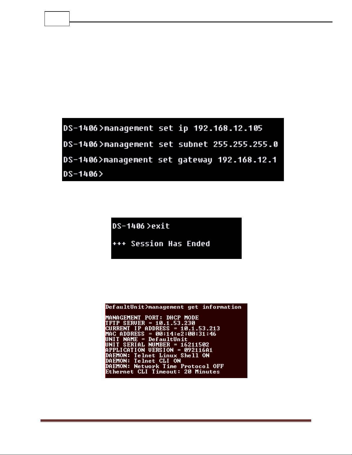
Step 5: Set up the IP address, subnet, and gateway on the device to match the network that
the management port is connected to. This can be done by using the commands:
o MANAGEMENT SET IP (<IP address> | “DHCP”)
o MANAGEMENT SET SUBNET <Subnet mask>
o MANAGEMENT SET GATEWAY <Gateway IP address>
o EXIT
You must enter the “exit” command and log back into the DURAstream™ before the
changes are applied.
Step 6: Once you have logged back in to the device, enter the “management get info”
command. This will display setting information regarding the management port. Verify
that the settings are correct.
You may choose to configure the DURAstream™ using either the serial port or the
management port. All configuration capabilities are the same for each connection method.
Datacom Systems Inc. 2016
Page 18

18
DURAstream™ DS-1404, DS-1406, DS-2408 FASTstart Guide
4 Management Connection
4.1 Setup
Once the management port configuration on the DURAstream™ has been set up to match
your chosen network location, you must next connect the straight through CAT5 cable to
your network.
NOTE: In situations where the management port is connected directly to a laptop or PC, a
crossover cable may be required.
When the cable is connected, the LED light on the left side of the port will illuminate
green. This indicates that a link has been established with the device on the other end of
the cable. The LED on the right side of the port will occasionally blink green when traffic
is being passed.
To confirm that there is connectivity between the DURAstream™ and the connected
device, open a terminal and ping the IP address of the DURAstream™.
Datacom Systems Inc. 2016
Page 19

19
DURAstream™ DS-1404, DS-1406, DS-2408 FASTstart Guide
4.2 Connecting via Telnet
Once the Management port is configured and connected to the network, the
DURAstream™ may be configured using a CLI over Telnet.
After confirming network connectivity in step 4.1, a terminal emulator may be used to
configure the device.
The following steps show the process for connecting to the DURAstream™ through
Telnet. The images used in the steps are from the terminal emulator Tera Term. Most
terminal emulators can be used to connect to the DURAstream™, however using either
Tera Term or Putty is recommended.
Step 1: Open the terminal emulator. Select Telnet as a method for connection.
Step 2: Enter the IP address of the DURAstream in the Host field. Click “OK”
Datacom Systems Inc. 2016
Page 20

20
DURAstream™ DS-1404, DS-1406, DS-2408 FASTstart Guide
Step 2: Enter the IP address of the VERSAstream in the Host field. Click “OK”
Step 4: To confirm that connection to the correct device was made, enter the “system get
info” command to view unique identifiers for the unit such as the Serial Number and MAC
Address.
Datacom Systems Inc. 2016
Page 21

21
DURAstream™ DS-1404, DS-1406, DS-2408 FASTstart Guide
5 Bypass Terminology Explanation
5.1 Overview
DURAstream™ Bypass Switches allow you to customize various attributes of the
heartbeat packets that are used to determine appliance health. They are shipped
programmed with recommended settings, but can be changed dynamically. The default
settings are suited for most use cases, but can be easily modified to change the parameters
of how the DURAstream™ interacts with the appliance.
5.2 Heartbeat Frequency
The frequency setting will determine how often heartbeats are sent out to the appliance.
Setting the frequency setting to 100ms will cause the bypass switch to send out a total of
10 heartbeats every second.
As the heartbeat transmission rate is increased, the responsiveness to an appliance failure
can be increased.
Datacom Systems Inc. 2016
Page 22

22
DURAstream™ DS-1404, DS-1406, DS-2408 FASTstart Guide
5.3 Heartbeat Expiration
The Heartbeat Expiration configuration controls the length of time that the DURAstream™
will wait before considering a heartbeat lost. Setting the Heartbeat Expiration to 200ms
will cause all heartbeats that have not arrived back at the DURAstream™ within 200ms to
be considered lost. If they are received after this 200ms period of time, they will not be
considered a successful heartbeat.
In scenarios where the appliance is expected to have some delay, a longer Heartbeat
Expiration setting may be more suitable.
In scenarios where minimal latency is expected to be introduced to the link by the
appliance, a shorter Heartbeat Expiration setting may be more suitable.
Datacom Systems Inc. 2016
Page 23

23
DURAstream™ DS-1404, DS-1406, DS-2408 FASTstart Guide
5.4 Heartbeat Fail Count
The Heartbeat Fail Count controls how many consecutive heartbeats must be missed in
order for the DURAstream™ to determine that action should be taken to bypass the
appliance.
The lower the fail count is set to, the faster the DURAstream™ will take action to bypass
the appliance. This is recommended for scenarios where network traffic flow has priority
over appliance control over traffic.
The higher the fail count is set to, the greater the time the DURAstream™ will wait before
it takes action to bypass the appliance. This is recommended for scenarios where appliance
control over traffic is critical.
Datacom Systems Inc. 2016
Page 24

24
DURAstream™ DS-1404, DS-1406, DS-2408 FASTstart Guide
5.5 Heartbeat Reactivation Count
The Heartbeat Reactivation Count controls how many consecutive heartbeats must be
passed in order for the DURAstream™ to determine that the appliance should be put back
inline on the link.
The lower the Reactivation count is set to, the faster the DURAstream™ will put the
appliance back inline. This is recommended for scenarios where appliance control over
traffic is critical.
The higher the Reactivation count is set to, the longer the DURAstream™ will wait before
putting the appliance back inline. This is recommended for scenarios where network traffic
flow has priority over appliance control over traffic.
Datacom Systems Inc. 2016
Page 25

25
DURAstream™ DS-1404, DS-1406, DS-2408 FASTstart Guide
5.6 Heartbeat Direction
The Heartbeat Direction setting controls direction that heartbeats are inserted in. By
default (UNI), the heartbeats will always transmit out the odd port, and be received on
the even port. Setting this field to BIDI will cause each appliance port to both transmit
and receive heartbeats simultaneously.
BiDi is recommended for appliances which are designed to monitor both ingress and
egress sides of traffic flow.
Datacom Systems Inc. 2016
Page 26

26
DURAstream™ DS-1404, DS-1406, DS-2408 FASTstart Guide
5.7 Heartbeat Packet Type
The Heartbeat Packet setting determines the format of the heartbeat packet that is sent out.
It’s recommended to choose the heartbeat type that matches the network traffic, and also
the type of traffic that the appliance is designed to pay attention to.
If an appliance is looking primarily at TCP exchanges, a TCP heartbeat is likely to give the
most accurate measurement of the health of the appliance.
The following packet types are available:
Ethernet 0x88b5
ICMP echo
IPX
TCP-SYN
UDP
Datacom Systems Inc. 2016
Page 27
27
DURAstream™ DS-1404, DS-1406, DS-2408 FASTstart Guide
5.8 System Bypass Modes
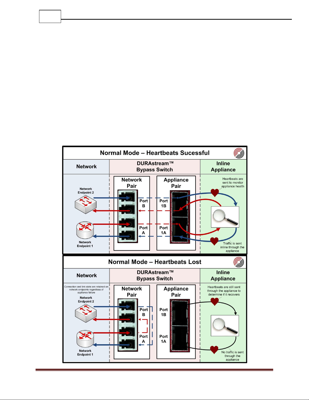
5.8.1 Normal
When set to Normal mode, the DURAstream™ will transmit heartbeats to the appliance to
monitor its health. If the DURAstream™ determines that the appliance is healthy based on
user specified criteria, it will direct traffic through the appliance ports.
If heartbeats do not arrive on the appliance ports, the DURAstream™ will switch to bypass
mode. In this mode traffic will bypass the appliance and be directly routed from one
network port to another. The rerouting of traffic does not cause link loss on the network
ports, which minimizes the transition time between the appliance being inline, and
bypassing it.
Datacom Systems Inc. 2016
Page 28
28
DURAstream™ DS-1404, DS-1406, DS-2408 FASTstart Guide
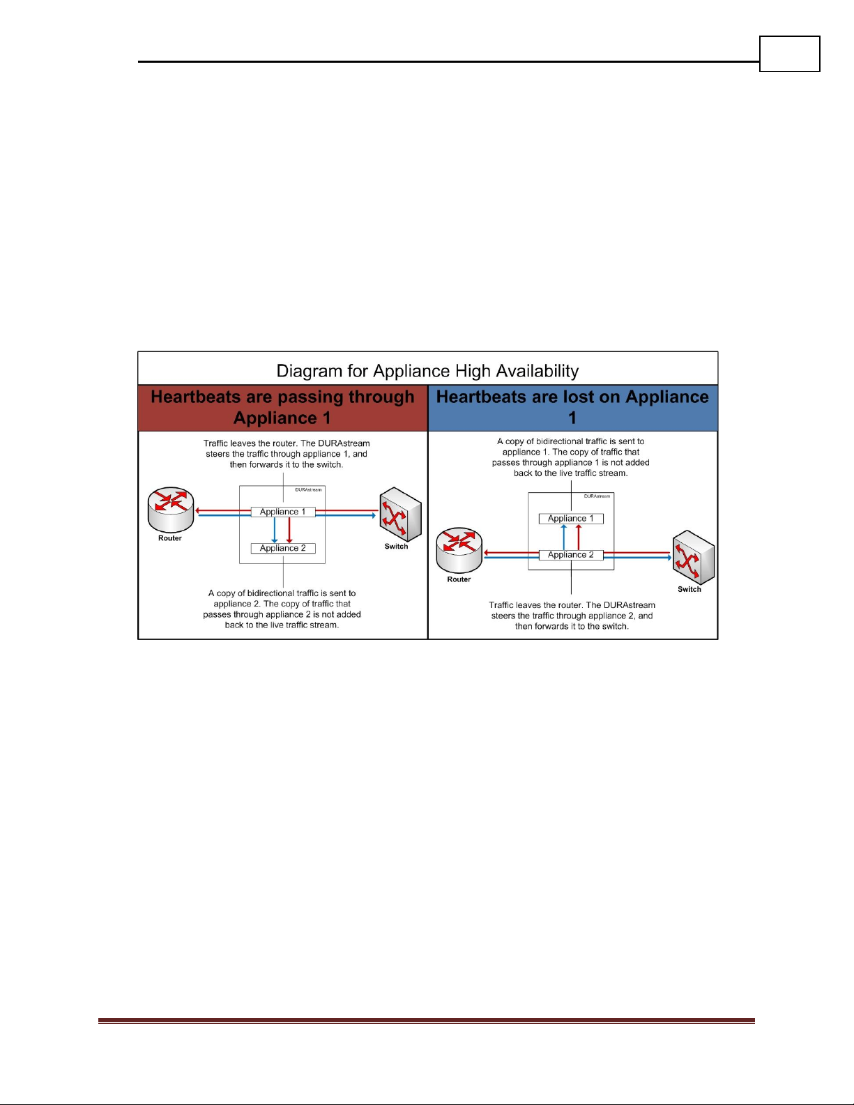
5.8.2 Normal High Availability
The high availability feature is available in DS-1406 and DS-2408 models. The feature makes use of all 4
appliance ports on the bypass switch. When activated, the bypass switch can only be used to route
traffic from a single network link.
High Availability mode reserves the second pair of appliance ports and assigns them to the first pair of
network ports as backup appliance ports.
If both appliance pairs are not operational (heartbeats are missing) the network pair will bypass as it
does in Normal mode. The DURAstream™ sends traffic directly between network ports, removing both
appliances from the stream of traffic.
Datacom Systems Inc. 2016
Page 29

29
DURAstream™ DS-1404, DS-1406, DS-2408 FASTstart Guide
Datacom Systems Inc. 2016
Page 30

30
DURAstream™ DS-1404, DS-1406, DS-2408 FASTstart Guide
Datacom Systems Inc. 2016
Page 31

31
DURAstream™ DS-1404, DS-1406, DS-2408 FASTstart Guide
Datacom Systems Inc. 2016
Page 32

32
DURAstream™ DS-1404, DS-1406, DS-2408 FASTstart Guide
5.8.3 Manual Inline
When set to Manual Inline mode, the DURAstream™ will forcefully put a connected
appliance inline. No heartbeats are transmitted in this mode, meaning that the
DURAstream™ is not able to monitor the health of the appliance.
When put into this mode, loss of link to the appliance ports will not cause the traffic to
bypass. This mode can be used when testing a new appliance to prevent the bypass switch
from going into bypass mode.
Datacom Systems Inc. 2016
Page 33

33
DURAstream™ DS-1404, DS-1406, DS-2408 FASTstart Guide
5.8.4 Manual Bypass
When set to Manual Bypass mode, the DURAstream™ will isolate the appliance from the
network link. No traffic is sent to the appliance, however heartbeats are still sent in order to
maintain a record of the appliance’s health.
This mode is generally used when the appliance needs to be taken out of the stream of
traffic, but link and network connectivity cannot be interrupted.
When switching to this mode from all other modes with the exception of Passive Bypass,
there is no link downtime for the network endpoints. When switching from Passive
Bypass, there is a brief link loss of connection that is mostly dependant on the negotiation
speed of the Network Endpoints.
Datacom Systems Inc. 2016
Page 34

34
DURAstream™ DS-1404, DS-1406, DS-2408 FASTstart Guide
5.8.5 Passive Bypass
When set to Passive Bypass mode, the DURAstream™ will isolate itself and the appliance
from the network link. A passive connection to the network will be created, where the
Network Endpoints directly negotiate speed with each other, rather than the Network Pair.
During this time if there is an active appliance connected to the DURAstream™, heartbeats
will be sent out to monitor it’s health, however it will not receive network traffic.
This mode is used for link or bypass troubleshooting the DURAstream™ by allowing the
network to function as if it were not inline.
If there is an active connection between the Network Endpoints and the DURAstream™,
switching to this mode will result is a brief loss of connection that is mostly dependant on
the negotiation speed of the Network Endpoints.
In the rare event of a power loss to the DURAstream™, the network pair will
automatically assume this mode, allowing traffic to continue to flow.
Datacom Systems Inc. 2016
Page 35

35
DURAstream™ DS-1404, DS-1406, DS-2408 FASTstart Guide
Usage
Guidelines
Use this command to retrieve information from all bypass fields. This will also
print the configurable heartbeat information and bypass current state.
Syntax
BYPASS GET INFO
Example
BYPASS GET INFO
Usage
Guidelines
Use this command to reset all port counters for heartbeats that are shown in
the output for the “BYPASS GET INFO” command.
Syntax
BYPASS GET INFO RESET
Example
BYPASS GET INFO RESET
Usage
Guidelines
Use this command to set the direction that heartbeats are inserted in. By
default (UNI), the heartbeats will always transmit out the odd port, and be
received on the even port. Setting this field to BIDI will cause each appliance
port to both transmit and receive heartbeats simultaneously.
Syntax
BYPASS SET DIRECTION <UNI,BIDI>
Example
BYPASS SET DIRECTION UNI
Command
Notes
It’s important to make sure that heartbeats will make it through your
appliance bidirectionally before setting this field to BIDI.
6 Command List
6.1 Bypass Commands
6.1.1 Bypass Get Info
6.1.2 Bypass Get Info Reset
6.1.3 Bypass Set Direction
Datacom Systems Inc. 2016
Page 36

36
DURAstream™ DS-1404, DS-1406, DS-2408 FASTstart Guide
Usage
Guidelines
Use this command to set the period of time that the bypass switch will wait,
starting at the point of transmission, before considering a heartbeat packet to
be lost. If it takes more than the defined period of time for a heartbeat to arrive
at the second appliance port of the pair, it will be counted as lost. This
heartbeat loss will count towards the “Bypass Set Fail” and “Bypass Set
Reactivate” command counters.
Syntax
BYPASS SET EXPIRE (100-10000)
Example
BYPASS SET EXPIRE 200
Command
Notes
The number field in the command indicates the number of milliseconds
before counting the heartbeat as lost.
It’s recommended to set the expire count to be low enough that the
DURAstream will be able to detect abnormalities, but high enough that
it doesn’t occasionally drop heartbeats during normal operation.
Usage
Guidelines
Use this command to set the number of heartbeats that must be missed
consecutively to trigger a failover. Heartbeats are considered missed once they
hit the threshold defined by the “bypass set expire” command.
Syntax
BYPASS SET FAIL (1-30)
Example
BYPASS SET FAIL 3
Command
Notes
Once the number of consecutive heartbeats lost reaches the value set
by this command, traffic will directly be sent between the network port
pair.
Usage
Guidelines
Use this command to set the rate at which heartbeats are transmitted out the
appliance port(s).
Syntax
BYPASS SET FREQUENCY (100-1000)
Example
BYPASS SET FREQUENCY 200
Command
Notes
The number field in the command indicates the number of milliseconds
between heartbeat transmissions.
6.1.4 Bypass Set Expire
6.1.5 Bypass Set Fail
6.1.6 Bypass Set Frequency
Datacom Systems Inc. 2016
Page 37

37
DURAstream™ DS-1404, DS-1406, DS-2408 FASTstart Guide
Usage
Guidelines
This command is used to set the current operating mode of the Bypass
Segment.
Syntax
BYPASS SET MODE (NORMAL, NORMAL HIGH AVAILABILITY, MANUAL
INLINE, MANUAL BYPASS, PASSIVE BYPASS)
Example
BYPASS SET MODE Normal
Command
Notes
Mode Options:
“Normal” – Bypass/Inline State Dependant on Heartbeats.
“Normal High Availability” – Dual Appliances Heartbeat Mode.
“Manual Inline” – Permanent Inline Appliance Mode.
“Manual Bypass” – Permanent Network Bypass Mode.
“Passive Bypass” – Permanent DURAstream Bypass Mode.
Usage
Guidelines
Use this command to set the type of heartbeats that the DURAstream sends
through the appliance.
Syntax
BYPASS SET PACKET <IPX. TCP-SYN, UDP, ETH, ICMP
Example
BYPASS SET PACKET TCP-SYN
Command
Notes
If your appliance looks for a specific packet type, it’s recommended to
set the heartbeat packet type to match it. This will provide the most
accurate analysis of the appliance.
Usage
Guidelines
Use this command to set the number of heartbeats that must arrive at the
appliance ports consecutively to for the DURAstream to consider the appliance
active.
Syntax
BYPASS SET REACTIVATE (1-30)
Example
BYPASS SET REACTIVATE 3
Command
Notes
Traffic will be sent back through the appliance when the reactivate
count is reached. The reactivate count is incremented when a heartbeat
packet successfully makes it back to the DURAstream before the time
indicated in the “bypass set expire” command.
6.1.7 Bypass Set Mode
6.1.8 Bypass Set Packet
6.1.9 Bypass Set Reactivate
Datacom Systems Inc. 2016
Page 38

38
DURAstream™ DS-1404, DS-1406, DS-2408 FASTstart Guide
Usage
Guidelines
Use this command to display all configurable email settings.
Syntax
EMAIL GET SETTINGS
Example
EMAIL GET SETTINGS
Command
Notes
Displays the following configurable values:
Email Source/Destination
Email Password
Email Server
Email Triggers
o -Link State
o -Heartbeat Loss
o -Failover Change
o -Power Supply Failure
o -Boot
Usage
Guidelines
Use this command to send a test email using the configured Source/Destination
IP, Server, and Password. Recommended to verify connectivity between the
DURAstream and the server.
Syntax
EMAIL SEND TEST
Example
EMAIL SEND TEST
Usage
Guidelines
Use this command to set the password for the email Source.
Syntax
EMAIL SET PASSWORD
Example
EMAIL SET PASSWORD
Command
Notes
If the entered password is not the exact password for the email source
address, email notifications will not be sent.
The email password is case-sensitive.
6.2 Email Notification Commands
6.2.1 Email Get Settings
6.2.2 Email Send Test
6.2.3 Email Set Password
Datacom Systems Inc. 2016
Page 39

39
DURAstream™ DS-1404, DS-1406, DS-2408 FASTstart Guide
Usage
Guidelines
Use this command to set the Destination for the email notifications. This email
address will receive notifications for all triggers that are turned on.
Syntax
EMAIL SET DESTINATION (email@address.com)
Example
EMAIL SET DESTINATION monitoring@acmetest.com
Command
Notes
The email address is case-sensitive.
This should match an existing email address on the configured server.
Usage
Guidelines
Use this command to set the Source for the email notifications. The emails that
are sent to the destination address will show that they are from this sender.
Syntax
EMAIL SET SOURCE (email@address.com)
Example
EMAIL SET SOURCE notifications@acmetest.com
Command
Notes
The email address is case-sensitive.
This should match an existing email address on the configured server.
Usage
Guidelines
Use this command to set the server address that the DURAstream will use to
send out email notifications.
Syntax
EMAIL SET SERVER (mail.server.com)
Example
EMAIL SET SERVER west.exch12345.serverdata.net
6.2.4 Email Set Destination
6.2.5 Email Set Source
6.2.6 Email Set Server
Datacom Systems Inc. 2016
Page 40

40
DURAstream™ DS-1404, DS-1406, DS-2408 FASTstart Guide
Usage
Guidelines
Use this command to decide when to send out an email notification. Email
Notifications can be sent out based on link state changes, heartbeats
lost/arrived, Failover Status Change, Power Supply Status Change, and During a
Warm/Cold Boot.
Syntax
EMAIL SET TRIGGER <Feature> (ON/OFF)
Example
EMAIL SET TRIGGER Heartbeat ON
Command
Notes
Feature Triggers Available:
Link
Heartbeat
Failover
Power
Boot
*
Usage
Guidelines
This command is used to print current IP information for the management port,
in addition to system information.
Syntax
MANAGEMENT GET INFO
Example
MANAGEMENT GET INFO
Command
Notes
Displays:
DHCP/Static mode
IP, Subnet, Gateway
DNS Server IP
TFTP Server IP
MAC Address
System Name, Serial Number, Firmware Version.
Telnet State
NTP State
Command Line Timeout
6.2.7 Email Set Trigger
6.3 Management Port Commands
6.3.1 Management Get Info
Datacom Systems Inc. 2016
Page 41

41
DURAstream™ DS-1404, DS-1406, DS-2408 FASTstart Guide
Usage
Guidelines
This command is used to resend the DHCP Discovery manually.
Syntax
MANAGEMENT RESET
Example
MANAGEMENT RESET
Usage
Guidelines
This command is used to set the telnet command line timeout. If there is no
activity from a Telnet login from within the time specific by this command, they
will be disconnected.
Syntax
MANAGEMENT SET CLI TIMEOUT <1-1000>
Example
MANAGEMENT SET CLI TIMEOUT 100
Command
Notes
The number component of the command determines the timeout in
minutes.
Only enter positive values into the timeout field.
Usage
Guidelines
This command is used to set the telnet command line on or off.
Syntax
MANAGEMENT SET DAEMON CLI <ON/OFF>
Example
MANAGEMENT SET DAEMON CLI ON
Command
Notes
If turned off, connections through Telnet will not be accepted by the
DURAstream.
Usage
Guidelines
This command is used to set the ability for remote login to recovery.
Syntax
MANAGEMENT SET DAEMON SHELL <ON/OFF>
Example
MANAGEMENT SET DAEMON SHELL ON
6.3.2 Management Reset
6.3.1 Management Set CLI Timeout
6.3.2 Management Set Daemon CLI
6.3.3 Management Set Daemon Shell
Datacom Systems Inc. 2016
Page 42

42
DURAstream™ DS-1404, DS-1406, DS-2408 FASTstart Guide
Usage
Guidelines
This command is used to set the NTP Feature on or off.
Syntax
MANAGEMENT SET DAEMON NTPD <ON/OFF>
Example
MANAGEMENT SET DAEMON NTPD ON
Command
Notes
When turned on, the unit will use the configured NTP server to
determine the Date/Time instead of the manually configured values.
Usage
Guidelines
This command is used to configure the IP address for the Dynamic Host
Configuration Protocol (DHCP) server. This is an alternative to setting the
IP/Subnet/Gateway information manually.
Syntax
MANAGEMENT SET DHCP <IPv4 address>
Example
MANAGEMENT SET DNS 192.168.1.28
Command
Notes
When turned on, the static IP information entered the “Management
set IP”, “Management Set Subnet”, and “Management Set Gateway”
commands will no longer be used. It’s recommended that you do not
activate this command unless you have serial access to the DURAstream
at the time of issuing it.
Usage
Guidelines
This command is used to configure the IP address for the Domain Name System
(DNS).
Syntax
MANAGEMENT SET DNS <IPv4 address>
Example
MANAGEMENT SET DNS 192.168.1.26
6.3.4 Management Set Daemon NTPD
6.3.1 Management Set DHCP
6.3.2 Management Set DNS
Datacom Systems Inc. 2016
Page 43

43
DURAstream™ DS-1404, DS-1406, DS-2408 FASTstart Guide
Usage
Guidelines
This command is used to configure the IP address for the management port on
the switch.
Syntax
MANAGEMENT SET IP <IPv4 address or “DHCP”>
Example
MANAGEMENT SET IP 192.168.1.25
Command
Notes
By Entering “DHCP” in the address field, it will turn on DHCP to
automatically resolve all IP information from a DHCP server.
Usage
Guidelines
This command is used to configure the gateway address for the management
port on the switch.
Syntax
MANAGEMENT SET GATEWAY <IPv4 address>
Example
MANAGEMENT SET GATEWAY 192.168.1.1
Usage
Guidelines
This command is used to change the password to log into the DURAstream.
Syntax
MANAGEMENT SET PASSWORD <string>
Example
MANAGEMENT SET PASSWORD DatacomPass4321
Command
Notes
Entering this command will replace the default password “admin” for
the user.
Usage
Guidelines
This command is used to configure the subnet address for the management
port on the switch.
Syntax
MANAGEMENT SET SUBNET <IPv4 address>
Example
MANAGEMENT SET SUBNET 255.255.255.0
6.3.3 Management Set IP
6.3.4 Management Set Gateway
6.3.5 Management Set Password
6.3.6 Management Set Subnet
Datacom Systems Inc. 2016
Page 44

44
DURAstream™ DS-1404, DS-1406, DS-2408 FASTstart Guide
Usage
Guidelines
This command is used to configure the IP address for the TFTP Server that the
DURAstream will communicate with.
Syntax
MANAGEMENT SET TFTPSERVER <IPv4 address>
Example
MANAGEMENT SET TFTPSERVER 192.168.1.25
Command
Notes
The DURAstream can use the TFTP server to send system log files, and to
receive new firmware versions for upgrading.
Usage
Guidelines
This command is used to change the username to log into the DURAstream.
Syntax
MANAGEMENT SET USERNAME <string>
Example
MANAGEMENT SET USERNAME AuthUser
Command
Notes
Entering this command will replace the default “Administrator” user.
Usage
Guidelines
This command is used to display all information for a port, or set of ports.
Syntax
PORT (1,2,3,4,5,6,7,8,*) GET INFO
Example
PORT 6 GET INFO
Command
Notes
Fields Displayed:
Media Type
Configured Speed
Link Status
Current Traffic Routing
6.3.7 Management Set TFTPServer
6.3.8 Management Set Username
6.4 Port Commands
6.4.1 Port Get Info
Datacom Systems Inc. 2016
Page 45

45
DURAstream™ DS-1404, DS-1406, DS-2408 FASTstart Guide
Usage
Guidelines
This command is used to display port counter information for a port, or set of
ports. Simple counter output that shows Tx and Rx packets.
Syntax
PORT (1,2,3,4,5,6,7,8,*) GET COUNTER
Example
PORT GET COUNTER
Command
Notes
Fields Displayed:
Rx Packets
Tx Packets
Rx Bytes
Tx Bytes
Usage
Guidelines
This command is used to display port counter information for a port, or set of
ports. This option will display various packet counters that are used for
diagnostic purposes.
Syntax
PORT (1,2,3,4,5,6,7,8,*) GET COUNTER Detail
Example
PORT GET COUNTER Detail
Command
Notes
Fields Displayed:
RX Packets
TX Packets
Rx Bytes
Tx Bytes
Various Diagnostic Fields
Usage
Guidelines
This command is used reset the port counters for a port or set of ports.
Syntax
PORT (1,2,3,4,5,6,7,8,*) RESET COUNTER
Example
PORT * RESET COUNTER
6.4.2 Port Get Counter
6.4.3 Port Get Counter Detail
6.4.4 Port Reset Counter
Datacom Systems Inc. 2016
Page 46

46
DURAstream™ DS-1404, DS-1406, DS-2408 FASTstart Guide
Usage
Guidelines
This command is used to change the media type of an appliance port from fiber
to copper or vice versa.
Syntax
PORT (3,4,5,6,*) SET MEDIA <Copper,Fiber>
Example
PORT ALL SET MEDIA FIBER
Command
Notes
Use this command in combination with the “Port Set Speed” command
to set up the DURAstream ports to match the appliance.
Using the “*” Symbol will change all ports.
Usage
Guidelines
This command is used to change the speed of the port. Use it to make the port
on the DURAstream the same as the attached Network endpoint or appliance.
Syntax
PORT (1,2,3,4,5,6,7,8,*) SET SPEED <speed>
Example
PORT ALL SET SPEED 10G
Command
Notes
Network Port Possible Speeds:
Fiber
1G-AUTO
1G-MANUAL
10G
Appliance Port Possible Speeds:
Copper
10M
100M
1G
Fiber
1G-AUTO
1G-MANUAL
10G
6.4.5 Port Set Media
6.4.6 Port Set Speed
Datacom Systems Inc. 2016
Page 47

47
DURAstream™ DS-1404, DS-1406, DS-2408 FASTstart Guide
Usage
Guidelines
This command is used to reboot the bypass switch. During the reboot, the link
will be passively closed in order to allow link state for part of the duration of the
reboot.
Syntax
SWITCH RESTART
Example
SWITCH RESTART
Command
Notes
This command is case sensitive, and has no shortcut version. You must
type it out in all caps.
Usage
Guidelines
This command is used to reset the configuration on the DURAstream to its outof-the box settings. A system reboot will take place once this command is
issued.
Syntax
RESET TO FACTORY DEFAULTS
Example
RESET TO FACTORY DEFAULTS
Command
Notes
This command is case sensitive, and has no shortcut version. You must
type it out in all caps.
Usage
Guidelines
This command is used to upgrade the firmware on the DURAstream. Once the
command is issued, the DURAstream will attempt to download and install the
firmware file located on the user configured TFTP server. Make sure that there
is connectivity between the TFTP server and DURAstream before using this
command.
Syntax
UPDATE SYSTEM FIRMWARE
Example
UPDATE SYSTEM FIRMWARE
Command
Notes
This command is case sensitive, and has no shortcut version. You must
type it out in all caps.
6.5 Switch Commands
6.5.1 Switch Restart
6.5.2 Reset To Factory Defaults
6.5.3 Update System Firmware
Datacom Systems Inc. 2016
Page 48

48
DURAstream™ DS-1404, DS-1406, DS-2408 FASTstart Guide
Usage
Guidelines
This command is used to display all system information.
Syntax
SWITCH GET INFO
Example
SWITCH GET INFO
Command
Notes
Fields Displayed:
Product Model
Current Operating Mode
Firmware Version
System Name
System Serial Number
System Time
NTP Server / Time Zone
Usage
Guidelines
This command is used to clear the current system logfile that contains
commands entered, logins, and events.
Syntax
SYSTEM RESET LOGFILE
Example
SYSTEM RESET LOGFILE
Command
Notes
Entering this command will remove all historical information regarding
commands entered, users logged in, and events from the DURAstream.
6.6 System Commands
6.6.1 System Get Info
6.6.1 System Reset Logfile
Datacom Systems Inc. 2016
Page 49

49
DURAstream™ DS-1404, DS-1406, DS-2408 FASTstart Guide
Usage
Guidelines
This command is used to send the current log file to the configured TFTP server.
The IP address of the TFTP server that is used is taken from the “MANAGEMENT
SET TFTPSERVER” command.
Syntax
SYSTEM SEND LOGFILE
Example
SYSTEM SEND LOGFILE
Command
Notes
The Log File Includes:
Command Inputs
System Name.
System IP Address.
User that issued.
Exact string entered.
Timestamp
Events
System Name.
System IP Address.
Event that occurred (Cold boot, Port state change, etc)
Timestamp
User Logins
System Name.
System IP Address.
User that Logged in.
Login Method (Telnet, Serial, etc)
Timestamp
Usage
Guidelines
This command is used set the system name that is displayed in the prompt, and
used in other features such as the prompt, system log, and email notifications.
Syntax
SYSTEM SET NAME <string>
Example
SYSTEM SET NAME DURAstream-Lab-04
Command
Notes
Name field can be a maximum of 31 characters.
6.6.2 System Send Logfile
6.6.3 System Set Name
Datacom Systems Inc. 2016
Page 50

50
DURAstream™ DS-1404, DS-1406, DS-2408 FASTstart Guide
Usage
Guidelines
This command is used set the NTP server that will be used to regulate the
DURAstreams Date/Time.
Syntax
SYSTEM SET NTPDSERVER (pool.ntp.org)
Example
SYSTEM SET NTPDSERVER (pool.ntp.org)
Command
Notes
Either set an IP address or the address of an NTP server.
Examples:
192.168.12.8
0.pool.ntp.org
Usage
Guidelines
This command is used set the time manually. This option is not available if NTP
is enabled.
Syntax
SYSTEM SET TIME (YEAR:MONTH:DAY:HOUR:MINUTE)
Example
SYSTEM SET TIME 2016:9:21:3:45
Command
Notes
If NTP is turned on and successfully connected, the user-configured
value in this field will be overwritten.
Usage
Guidelines
This command is used set the time zone that NTP will use to translate
information from the configured NTP server.
Syntax
SYSTEM SET ZONE (EST,CST,MST,PST,UTC-11,UTC+12)
Example
SYSTEM SET ZONE EST
Command
Notes
You can use UTC values between UTC-12 – UTC+14.
6.6.4 System Set NTPDserver
6.6.5 System Set Time
6.6.6 System Set Zone
Datacom Systems Inc. 2016
Page 51

51
DURAstream™ DS-1404, DS-1406, DS-2408 FASTstart Guide
7 Configuration Examples
7.1 Single Copper Appliance for a 1G Fiber Link.
Use Case: A single appliance scenario can be used on the DS-1404, DS-1406, and DS-
2408 models. It is used when a single appliance needs to be installed on a single network
link through the bypass switch. A single appliance solution requires one pair of network
ports, and one pair of appliance ports.
The network traffic will be directed to the inline appliance through the switch. In the event
that a failure is detected in the appliance, traffic is redirected around the appliance. This
allows the network connection to retain link state and experience minimal downtime from
the appliance failure.
In this scenario, the network link is 1G fiber, and the monitoring tool is 1G copper. It
would be difficult to otherwise install the copper tool onto the fiber network. In addition to
acting as a bypass switch, the Durastream™ also provides media conversion for the tool.
Datacom Systems Inc. 2016
Page 52

52
DURAstream™ DS-1404, DS-1406, DS-2408 FASTstart Guide
Example Configuration Commands
Management Port Setup
Command
Explanation
Management Set IP 192.168.1.2
If you plan to access the Durastream™ over a network,
you should first set up the IP information to connect to it
remotely. The configuration should match your
network’s topology.
Management Set Subnet 255.255.255.0
Management Set Gateway 192.168.1.1
Network Port Setup
Command
Explanation
Port 3 Set Speed 1G-Auto
Since the network link that the Durastream™ is
being installed on is 1G fiber, the ports must be
configured to 1G speed. They are fiber by default.
Port 4 Set Speed 1G-Auto
Appliance Port Setup
Command
Explanation
Port 3 Set Media Copper
Since a copper monitoring tool is being used,
the appliance ports (3 and 4) must be set to
copper media type and 1G speed.
Port 3 Set Speed Auto
Port 4 Set Media Copper
Port 4 Set Speed Auto
*Optional* Heartbeat Modification
Command
Explanation
Bypass Set Freq 100
Heartbeats are sent every 100ms.
Bypass Set Expire 100
DURAstream™ waits 100 ms before considering
a heartbeat to be missing.
Bypass Set Fail 3
If the DURAstream™ misses 3 consecutive
heartbeats it will bypass the appliance.
Bypass Set Reactivate 2
If the DURAstream™ receives 2 consecutive
heartbeats it will put the appliance inline.
Bypass Set Direction Uni
The DURAstream™ will send heartbeats on the
first appliance port, to be received by the second.
Bypass Set Packet Eth
The DURAstream™ will send Ethernet heartbeats
through the appliance.
Datacom Systems Inc. 2016
Page 53

53
DURAstream™ DS-1404, DS-1406, DS-2408 FASTstart Guide
*Optional* Email Notification Setup
Command
Explanation
Email Set Source john_doe@acme.com
Emails notifications will appear from the entered
email address.
Email Set Destination john_smith@acme.com
Emails notifications will arrive at the entered
email address.
Email Set Server 192.168.1.3
Email notifications will go through the entered
email server.
Email Set Password test
Password for the email server being used.
Datacom Systems Inc. 2016
Page 54

54
DURAstream™ DS-1404, DS-1406, DS-2408 FASTstart Guide
8 Customer Service
Datacom Customer Service is available via telephone and Internet. You may also find the
assistance you need at our website: http://www.datacomsystems.com.
Telephone: +1 315 463-9541
Internet website:
http://www.datacomsystems.com/support/contact-support
Datacom Systems Inc. 2016
Page 55

55
DURAstream™ DS-1404, DS-1406, DS-2408 FASTstart Guide
Datacom Systems Inc.
9 Adler Drive • East Syracuse, NY 13057
TEL: +1 315 463-9541 • FAX: +1 315 463-9557
http://www.datacomsystems.com
Datacom Systems Inc. 2016
 Loading...