

Page 1
Datacom Systems Inc
TM
Access Your Network
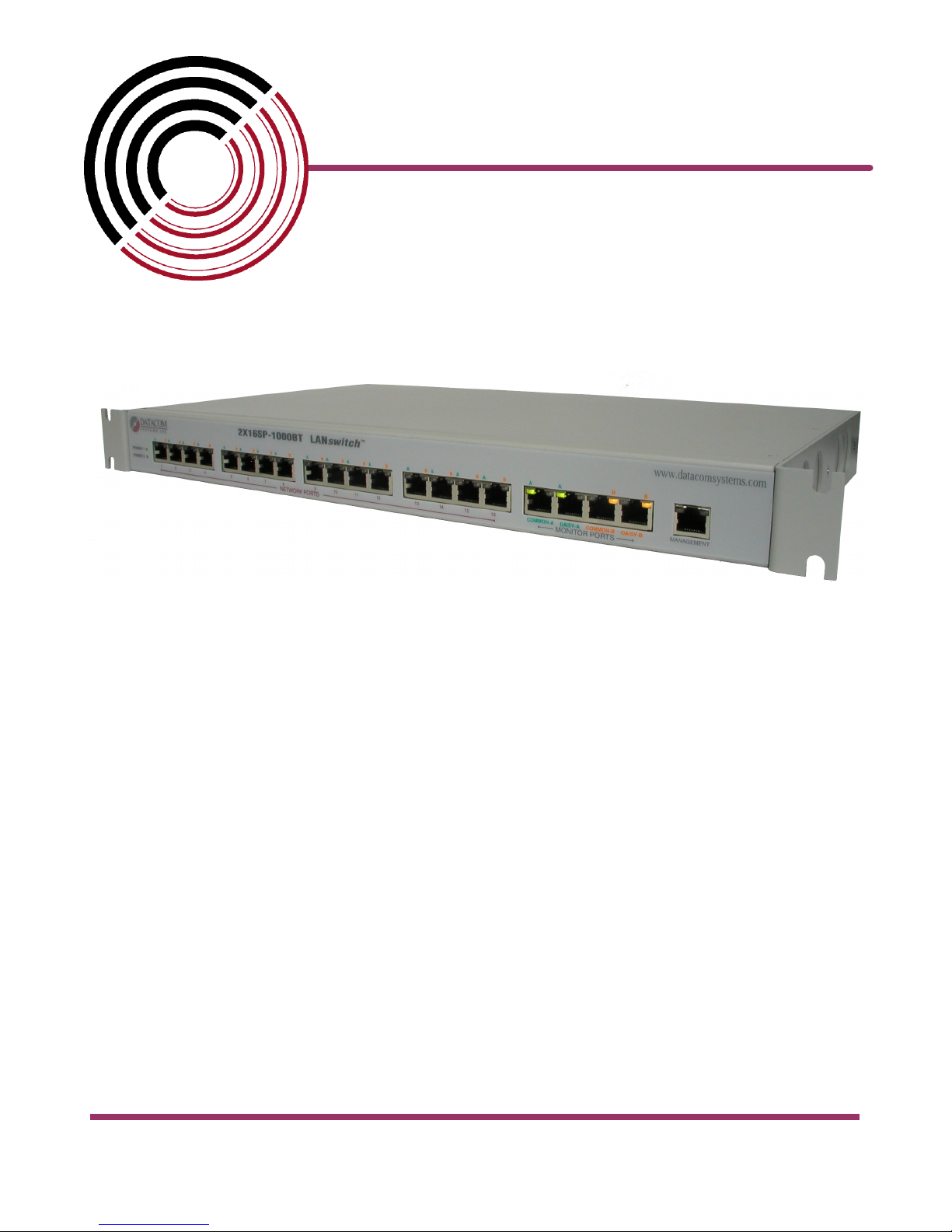
2X16SP-1000BT
October 2007
USER
© 2007 Datacom Systems Inc
guide
541-0109-U-A.02
Page 2

Page 3

Product Description
You realize how critical your 1000BT networks are to
your personal success and the success of your overall
network strategy. These 1000BT links carry a very high
volume of traffic across your network and are absolutely
vital to network performance. Virtually all of your
1000BT links are the very definition of mission critical.
It’s nothing new and no secret that the uptime of mission
critical segments must approach 100%. As a busy
network manager, when a problem occurs in a remote
closet, you can now handle the problem remotely with a
few keystrokes rather than physically going to the site.
Seamless switch control from the Datacom switch
control software console saves you precious time and is
an integral part of the 2X16SP-1000BT Gigabit SPAN
Matrix Switch.
The 2X16SP-1000BT Gigabit SPAN Matrix Switch
affords the ultimate in network integrity to meet whatever
monitoring or analysis requirements you may have and
allows the sharing of network tools between 1000BT
segments. Your tools can be quickly and effectively
targeted at the point of failure, expanding visibility to the
farthest reaches of your 1000BT networks.
Page 4

2X16SP-1000BT
© 2007 Datacom Systems Inc
All rights reserved. No parts of this work may be reproduced in any form or by any means - graphic, electronic, or
mechanical, including photocopying, recording, taping, or information storage and retrieval systems - without the
written permission of the publisher.
Products that are referred to in this document may be either trademarks and/or registered trademarks of the
respective owners. The publisher and the author make no claim to these trademarks.
While every precaution has been taken in the preparation of this document, the publisher and the author assume no
responsibility for errors or omissions, or for damages resulting from the use of information contained in this document
or from the use of programs and source code that may accompany it. In no event shall the publisher and the author be
liable for any loss of profit or any other commercial damage caused or alleged to have been caused directly or
indirectly by this document.
Printed: October 2007 in East Syracuse, New York
Page 5

Table of Contents
5Contents2X16SP-1000BT
Section 1
Section 2
Section 3
Terms of Use
................................................................................................................................... 71 Copyright
................................................................................................................................... 72 License Agreement
................................................................................................................................... 73 Trademark Attribution
................................................................................................................................... 74 Proprietary Notice
................................................................................................................................... 85 Certifications and Marks
Overview
................................................................................................................................... 91 What Shipped?
................................................................................................................................... 92 Features and Benefits
................................................................................................................................... 103 Specifications
Hardware
................................................................................................................................... 111 Front Panel Description
.......................................................................................................................................................... 11Power
.......................................................................................................................................................... 11Network Ports
.......................................................................................................................................................... 11Monitor Ports
.......................................................................................................................................................... 12Daisy Ports
.......................................................................................................................................................... 12Management Port
................................................................................................................................... 132 Rear Panel Description
.......................................................................................................................................................... 13Power
.......................................................................................................................................................... 13Control
.......................................................................................................................................................... 13Link
.......................................................................................................................................................... 13Input Power
.......................................................................................................................................................... 14Rear Label
7
9
11
Section 4
Section 5
Installation
................................................................................................................................... 151 IP Address
................................................................................................................................... 202 Hardware Installation
.......................................................................................................................................................... 20Power
.......................................................................................................................................................... 21Network Connection
.......................................................................................................................................................... 22Monitor Connection
.......................................................................................................................................................... 23Management Connection
................................................................................................................................... 243 Daisy-Chain Installation
.......................................................................................................................................................... 24Daisy-Chain Power, Network, Management Connection
.......................................................................................................................................................... 25Control-Link Connection
.......................................................................................................................................................... 26Monitor Connection
Customer Service
................................................................................................................................... 271 World Wide Web
................................................................................................................................... 272 Warranty
15
27
© 2007 Datacom Systems Inc
Page 6

2X16SP-1000BT6
................................................................................................................................... 283 Limits of Liability
© 2007 Datacom Systems Inc
Page 7

1 Terms of Use
The following terms and conditions relate to the use of this document. Please note that
Datacom Systems Inc. reserves the right, at its entire discretion, to change, modify, add, or
remove portions of these Terms of Use at any time. Please read the Terms of Use carefully as
your use of this document is subject to the Terms of Use stipulated herein.
1.1 Copyright
Copyright© 2007 by Datacom Systems, Inc. All rights reserved. Printed in the United States
of America. No part of this publication may be reproduced, stored in a retrieval system, or
transmitted, in any form or by any means, electronic, mechanical, photocopying, recording, or
otherwise, without the prior written permission of Datacom Systems, Inc. To obtain this
permission, write to the attention of the Datacom Systems legal department at 9 Adler Drive,
East Syracuse, New York 13057-1290, or call 315-463-9541.
1.2 License Agreement
Terms of Use 7
Notice To All Users: By using Datacom Systems, Inc. products, you agree to the terms set
forth. No licenses, express or implied, are granted with respect to the technology described
and Datacom Systems, Inc. retains all rights with respect to the technology described herein.
If applicable, you may return the product to the place of purchase for a full refund.
1.3 Trademark Attribution
Access Your Network™, DS3 ACTIVEtap™, DS3switch™, Empowering Network
Professionals™, ETHERNETtap™, FDDIswitch™, FIBERsplitter™, FIBERswitch™,
FIBERSWITCHsystem™, GIGABITswitch™, INSERTswitch™, INSERTunit™, LANswitch
™, MANAgents™, MULTINETswitch™, NETspan™, PERMAlink™, PROline™, RMON
SWITCHINGanalyzer™, SINGLEstream™, UNIVERSALswitch™, VERSAstream™, and
WANswitch™ are trademarks of Datacom Systems, Inc. 1ST in Switching Solutions®,
DATACOMsystems®, LANclipper®, MANAgents®, and MULTIview® are registered
trademarks of Datacom Systems, Inc. All other registered and unregistered trademarks are the
sole property of their respective owners. All specifications may be changed without notice.
1.4 Proprietary Notice
This document contains proprietary information about the 2X16SP-1000BT (2X16
10/100/1000 BaseT Copper Gigabit SPAN Matrix Switch with built in switch control) and is
not to be disclosed or used except as authorized by written contract with Datacom Systems,
Inc.
© 2007 Datacom Systems Inc
Page 8

2X16SP-1000BT8
1.5 Certifications and Marks
CAUTION: Changes or modifications to this unit not expressly approved by the party
responsible for compliance could void the user’s authority to operate the equipment.
© 2007 Datacom Systems Inc
Page 9

2 Overview
The 2X16SP-1000BT Gigabit SPAN Matrix Switch increases network visibility and leverages
your investment in network analyzers, probes, and security equipment by allowing you to
simultaneously monitor up to four separate ports. Greater visibility accelerates problem
resolution, reduces downtime and increases enterprise productivity.
Like all Datacom Systems matrix switches, the 2X16SP-1000BT matrix switch is compatible
with all vendor hardware and can be controlled by our MANAgents™ switch control
software, which will allow you to control all of your matrix switches through a single
interface regardless of what network appliances you choose to deploy.
2.1 What Shipped?
1 — 2X16SP-1000BT
2 — AC Line Cords
1 — DRL512-2M-R cables, DB9 M/F straight thru
1 — USERguide
1 — MANAgents™, software
Terms of Use 9
2.2 Features and Benefits
· SPAN 16 network segments for analysis
· Leverages up to two network appliances across 16 ports in 1000BT network
environments
· Daisy-chain up to four units to access up to 64 ports in 1000BT networks
· Central management of matrix switches eliminates the need to travel with portable
equipment
· Ideal for networks using distributed network analyzers - save money by deploying and
maintaining fewer devices on your network
· Optimal for network access and distribution layer visibility
· Remote deployment speeds problem resolution time
· Allows two protocol analyzers or other network devices to analyze/monitor the same
port
· Easily configured or switched through our MANAgents™ switch control software or
directly through the API of network analyzers
· Conveniently rack-mountable in only 1U (1.72")
© 2007 Datacom Systems Inc
Page 10

2X16SP-1000BT10
2.3 Specifications
Network Connections:
Sixteen (16) - RJ45 @ 10/100/1000BT
Monitor Ports:
Two (2) - RJ45 @ 10/100/1000BT
Daisy Ports:
Two (2) - RJ45 @ 10/100/1000BT
Management Port:
One (1) - RJ45 @ 100 Mbs Full-Duplex
Serial Port:
One (1) - DB9
Input Power Requirement:
Two (2) - 100-240VAC, 50-60Hz, 0.5-0.25A
Dimensions (H x W x D):
1.72 x 19.00 x 10.50 inch
4.37 x 48.26 x 26.67 cm
Weight:
5 lbs
1.42 kg
Operating Temperature:
0º to 40° C
Storage Temperature:
-30º to 65° C
Humidity:
Less than 95° C non-condensing
Warranty:
Two (2) years - see 5.2 Warranty section for details.
© 2007 Datacom Systems Inc
Page 11

3 Hardware
This section provides a description of the 2X16SP-1000BT Gigabit SPAN Matrix Switch.
3.1 Front Panel Description
This section provides a illustration and description of the front panel of the 2X16SP-1000BT
Gigabit SPAN Matrix Switch.
An explanation of each front panel legend follows:
3.1.1 Power
The POWER 1, POWER 2 LEDs illuminate green when the unit power is switched ON with
power available to both of the two rear AC power sockets. Although only one power supply is
required to power the 2X16SP-1000BT, use of a second independent power source is strongly
recommended to assure uninterrupted monitoring.
Overview 11
To power the unit ON: Power ON the 2X16SP-1000BT by depressing the AC power switch
bar icon. The powered ON 2X16SP-1000BT is indicated by the illuminated green POWER 1
and POWER 2 LEDs on the front panel when the AC power switch is depressed ON and AC
power is available at both the two rear AC power sockets. Either POWER 1, POWER 2 LED
not illuminated when powered ON indicates a defective power source and immediate
investigation as to the cause is required to insure redundant power integrity.
3.1.2 Network Ports
The NETWORK PORTS 1-16 are RJ45 shielded sockets used for connection to 16 network
segments with a straight-through LAN cable.
3.1.3 Monitor Ports
The MONITOR PORTS COMMON-A and COMMON-B are RJ45 shielded sockets used for
connection to network analysis tools with a straight-through LAN cable.
© 2007 Datacom Systems Inc
Page 12

2X16SP-1000BT12
3.1.4 Daisy Ports
The DAISY PORTS DAISY-A and DAISY-B are RJ45 shielded sockets used for connection to
another switch in the daisy-chain path with a straight-through LAN cable.
3.1.5 Management Port
The MANAGEMENT PORT is an RJ45 socket used for 100 Mbs full-duplex connection with a
straight-through LAN cable via your management LAN to a Remote Management Console
which is a standard PC running MANAgents™.
Link indicates connection. The LED Display Code table deciphers the RJ45 jacks with
integrated LEDs that display line status of the MANAGEMENT PORT.
© 2007 Datacom Systems Inc
Page 13

3.2 Rear Panel Description
This section provides a description of the rear panel of the 2X16SP-1000BT Gigabit SPAN
Matrix Switch.
An explanation of each rear panel legend follows:
3.2.1 Power
The AC POWER switch is a rocker style switch. The AC power switch circle icon depressed
is OFF. The AC power switch bar icon depressed is ON. To power the unit ON: Power ON the
2X16SP-1000BT by depressing the AC power switch bar icon. The powered ON 2X16SP-
1000BT is indicated by the illuminated green POWER 1 and POWER 2 LEDs on the front
panel.
Hardware 13
3.2.2 Control
The CONTROL connector port is a shielded DB9 Female and is cabled to the COM port of any
compatible network tool or PC where HyperTerminal or Datacom Systems Switch Control
Software resides.
If this 2X16SP-1000BT Gigabit SPAN Matrix Switch is daisy-chained the CONTROL port will
be connected to the preceding switch LINK port.
3.2.3 Link
The LINK connector port is a shielded DB9 Male and is cabled to the CONTROL port of the
succeedomg 2X16SP-1000BT Gigabit SPAN Matrix Switch when daisy-chained.
3.2.4 Input Power
Two AC input power sockets are provided on the rear panel. The front panel POWER 1,
POWER 2 LEDs are illuminated green, respectively, when the AC power switch is depressed
ON and AC power is available at both the two rear AC power sockets. Either POWER 1,
POWER 2 LED illuminated red indicates a defective power source and immediate
investigation as to the cause is required to insure redundant power integrity.
Although only one power supply is required to power the 2X16SP-1000BT, use of a second
independent power source is strongly recommended to assure uninterrupted monitoring.
Furthermore, connecting the second AC input power socket to a different external power
source circuit than the first AC input power source eliminates power as a single point of
failure.
© 2007 Datacom Systems Inc
Page 14

2X16SP-1000BT14
3.2.5 Rear Label
Input power requirements, Serial Number (SN) identifier, Media Access Control (MAC)
address identifier, certification compliance identifiers and various other information are
provided on this rear label.
© 2007 Datacom Systems Inc
Page 15

4 Installation
This section explains how to install the 2X16SP-1000BT Gigabit SPAN Matrix Switch
4.1 IP Address
All 2X16SP-1000BT Gigabit SPAN Matrix Switch are assigned an IP address (192.168.1.1)
by default. You must change the IP address to match your network.
NOTE: If your 2X16SP-1000BT already has an IP address for your network, you may proceed
to the MANAgents™ USERguide.
The IP address of the 2X16SP-1000BT can be configured via a serial connection made with
Microsoft's HyperTerminal application available on Windows PCs.
Step 1. First, connect your PC and your 2X16SP-1000BT using the provided Datacom
Systems DRL512-2M-R cable. Connect the DB9 Female pin end to the serial port on your PC
and connect the DB9 Male pin to the CONTROL port on your 2X16SP-1000BT.
Hardware 15
NOTE: For PCs without 9-pin serial ports, check with you product representative for available
sources of a USB to RS-232 Plug-in Adapter.
Step 2. Using a supplied AC Line Cord, plug the 2X16SP-1000BT Gigabit SPAN Matrix
Switch into the external power source. Note that either POWER 1 or POWER 2 LED is
illuminate green indicating power is available at the rear AC power socket to which the AC
Line Cord is connected. The other POWER LED is illuminated red indicating a lack of power
to the unconnected AC power socket. Depress the AC power switch bar icon to power ON the
2X16SP-1000BT which is indicated by the internal cooling fans powering up.
Step 3. Open the HyperTerminal application on your PC by selecting START > All Programs >
Accessories > Communications > HyperTerminal
© 2007 Datacom Systems Inc
Page 16

2X16SP-1000BT16
Step 4. Name a new HyperTerminal connection and select OK
© 2007 Datacom Systems Inc
Page 17

Installation 17
Step 5. On the Connect to window, create a serial link by selecting the COM port assigned to
the serial port on your PC from the en the HyperTerminal application on your PC from the Co
nnect using: pull-down menu and select OK
Step 6. Next, configure the COM Properties. The initial correct setting to communicate with
the 2X16SP-1000BT Gigabit SPAN Matrix Switch (2400, 8, None, 1, None) are shown
below.
Once all settings are configured correctly, click Apply, then click OK.
© 2007 Datacom Systems Inc
Page 18

2X16SP-1000BT18
Step 7. You are now connected to your 2X16SP-1000BT Gigabit SPAN Matrix Switch. Hit
the Enter key twice in succession (i.e., Enter, Enter) to display the Command shell prompt and
type ? to see a list of available commands.
Step 8. Set the IP address by typing SET IP xxx.xxx.xxx.xxx where xxx.xxx.xxx.xxx
corresponds to a valid IP address for your network. Press the Enter key to continue.
Step 9. Set the default gateway (if needed) by typing SET GATEWAY xxx.xxx.xxx.xxx
where xxx.xxx.xxx.xxx corresponds to your network's default gateway. Press the Enter key
to continue.
Step 10. Set the subnet mask by typing SET SUBNET xxx.xxx.xxx.xxx where xxx.xxx.xxx.
xxx corresponds to your network's subnet mask. Press the Enter key to continue.
Step 11. Type EXIT to save the network address changes and end the HyperTerminal session
your network. Press the Enter key to continue.
© 2007 Datacom Systems Inc
Page 19

Installation 19
Step 12. Hit the Enter key a couple of times to re-establish the connection with the 2X16SP1000BT Gigabit SPAN Matrix Switch and then type SHOW to review the network address
settings. Verify that the settings are correct.
Step 13. Type EXIT to close the HyperTerminal connection and close the HyperTerminal
window responding 'Yes' to the "Are you sure you want to disconnect now?' prompt.
Step 14. Disconnect the DRL512-2M-R serial cable from your 2X16SP-1000BT Gigabit
SPAN Matrix Switch.
Step 15. Proceed to install the 2X16SP-1000BT Gigabit SPAN Matrix Switch in your chosen
network location.
© 2007 Datacom Systems Inc
Page 20

2X16SP-1000BT20
4.2 Hardware Installation
This section will focus on a simple configuration which describes the typical 2X16SP1000BT Gigabit SPAN Matrix Switch hardware installation at the network location of your
choice.
4.2.1 Power
This section will focus on power at the installation network location of the 2X16SP-1000BT
Gigabit SPAN Matrix Switch.
Two AC input power sockets are provided on the rear panel. The front panel POWER 1,
POWER 2 LEDs are illuminated green, respectively, when the AC power switch is depressed
ON and AC power is available at both the two rear AC power sockets.
Step 1. Using the supplied AC Line Cords, plug the 2X16SP-1000BT SPAN Matrix Switch
into different circuit external power sources. Although only one power supply is required to
power the 2X16SP-1000BT, use of a second independent power source is strongly
recommended to assure uninterrupted monitoring. Furthermore, connecting the second AC
power socket to a different external power source circuit than the first AC power source
eliminates power as a single point of failure.
The AC POWER switch is a rocker style switch. The AC power switch circle icon depressed
is OFF. The AC power switch bar icon depressed is ON..
Step 2. Power ON the 2X16SP-1000BT by depressing the AC power switch bar icon. The
powered ON 2X16SP-1000BT is indicated by the illuminated green POWER 1 and POWER 2
LEDs on the front panel. Either POWER 1, POWER 2 LED not illuminated when powered ON
indicates a defective power source and immediate investigation as to the cause is required to
insure redundant power integrity.
© 2007 Datacom Systems Inc
Page 21

4.2.2 Network Connection
This section will focus on the NETWORK PORT connection of the typical 2X16SP-1000BT
Gigabit SPAN Matrix Switch hardware installation.
Installation 21
Step 1. Connect one of the network data cables to a NETWORK PORT socket.
Step 2. Continue repeating Step 1. for any remaining NETWORK PORT you want to connect
from the 2X16SP-1000BT Gigabit SPAN Matrix Switch.
© 2007 Datacom Systems Inc
Page 22

2X16SP-1000BT22
4.2.3 Monitor Connection
This section will focus on the MONITOR PORT connection of the typical 2X16SP-1000BT
Gigabit SPAN Matrix Switch hardware installation.
Step 1. Connect a monitoring cable (i.e., COMMON A or COMMON B) to a MONITOR PORT
socket and the other side of this monitoring cable to the monitoring tool NIC port. For this
example a cable is connected from COMMON A to the Analyzer monitoring tool NIC. This
supplies the monitored network data to the monitoring tool.
Step 2. Connect another monitoring cable (i.e., COMMON A or COMMON B) to a MONITOR
PORT socket and the other side of this monitoring cable to the monitoring tool NIC port. For
this example a cable is connected from COMMON B to the Network IDS monitoring tool NIC.
This supplies the monitored network data to the monitoring tool.
© 2007 Datacom Systems Inc
Page 23

4.2.4 Management Connection
This section will focus on the MANAGEMENT PORT 100 Mbs full-duplex connection of
the typical 2X16SP-1000BT Gigabit SPAN Matrix Switch hardware installation.
Installation 23
Step 1. Connect a network cable to the MANAGEMENT port RJ45 socket. The RJ45 left LEDs
illuminates green when link has been established with the network. The right LEDs
illuminates green when passing data.
Step 2. Refer to the MANAgents USERguide for detail operation of the 2X16SP-1000BT
Gigabit SPAN Matrix Switch.
© 2007 Datacom Systems Inc
Page 24

2X16SP-1000BT24
4.3 Daisy-Chain Installation
This section will focus on a simple daisy-chain configuration describing the typical hardware
daisy-chain installation of four 2X16SP-1000BT Gigabit SPAN Matrix Switches.
4.3.1 Daisy-Chain Power, Network, Management Connection
NOTE: Only the first 2X16SP-1000BT Gigabit SPAN Matrix Switches in the daisy-chain must
have its IP Address configured prior to installation in the daisy-chain. Refer to the 'IP
Address in the Installation' section.
NOTE: The 2X16SP-1000BT Gigabit SPAN Matrix Switch label 0 in the diagram is the first
switch in the daisy-chain, 1 is the second switch in the daisy-chain, 2 is the third switch in
the daisy-chain and 3 is the forth switch in the daisy-chain.
NOTE: All the daisy-chain switches are managed through the first switch in the daisy-chain.
Step 1. Refer to 'Power' under the 'Hardware Installation' section for the directions to connect
each switch in the daisy-chain to a power source.
Step 2. Refer to 'Network Connection' under the 'Hardware Installation' section for the
directions to connect each NETWORK PORT socket in the daisy-chain to a network.
Step 3. Refer to "Management Connection' under the 'Hardware Installation' section for the
directions to connect the MANAGEMENT port socket in the daisy-chain to a remote
management network.
© 2007 Datacom Systems Inc
Page 25

4.3.2 Control-Link Connection
NOTE: Only the first 2X16SP-1000BT Gigabit SPAN Matrix Switches in the daisy-chain must
have its IP Address configured prior to installation in the daisy-chain. Refer to the 'IP
Address in the Installation' section.
Installation 25
NOTE: The 2X16SP-1000BT Gigabit SPAN Matrix Switch label 0 in the diagram is the first
switch in the daisy-chain, 1 is the second switch in the daisy-chain, 2 is the third switch in
the daisy-chain and 3 is the forth switch in the daisy-chain.
NOTE: All the daisy-chain switches are managed through the first switch in the daisy-chain.
Step 1. For two switches daisy-chained, connect a DRL512-2M-R cable, DB9 M/F straight
thru cable, to the LINK DB9 socket of the first switch (switch 0) to the CONTROL DB9 socket
of the second switch (switch 1).
Step 2. If three switches are daisy-chained, continue. Connect a DRL512-2M-R cable, DB9
M/F straight thru cable, to the LINK DB9 socket of the second switch (switch 1) to the
CONTROL DB9 socket of the third switch (switch 2).
Step 3. If four switches are daisy-chained, continue. Connect a DRL512-2M-R cable, DB9 M/
F straight thru cable, to the LINK DB9 socket of the third switch (switch 2) to the CONTROL
DB9 socket of the fourth switch (switch 3).
© 2007 Datacom Systems Inc
Page 26

2X16SP-1000BT26
4.3.3 Monitor Connection
Step 1. Also refer to 'Monitor Connection' under the 'Hardware Installation' section for details
to connect each monitor tool to the first switch (i.e., COMMON A and COMMON B) in the
daisy-chain.
Step 2. For two switches daisy-chained, connect a straight-through LAN cable, to each of the
DAISY A and DAISY B sockets of the first switch (switch 0), respectively, to the COMMON A
and COMMON B sockets of the second switch (switch 1).
Step 3. If three switches are daisy-chained, continue. Connect a straight-through LAN cable,
to each of the DAISY A and DAISY B sockets of the second switch (switch 1), respectively, to
the COMMON A and COMMON B sockets of the third switch (switch 2).
Step 4. If four switches are daisy-chained, continue. Connect a straight-through LAN cable, to
each of the DAISY A and DAISY B sockets of the third switch (switch 2), respectively, to the
COMMON A and COMMON B sockets of the fourth switch (switch 3).
© 2007 Datacom Systems Inc
Page 27

5 Customer Service
This USERguide was written to help you get to know your new 2X16SP-1000BT Gigabit
SPAN Matrix Switch quickly and easily. We would welcome any comments or suggestions
you may have regarding this USERguide. Please send your remarks and recommendations via
mail, telephone, facsimile, or Internet E-mail.
Datacom Customer Service is available via telephone, facsimile, and Internet E-mail. Outside
of support hours, please leave a voice message and our Customer Service Staff will return
your call as soon as possible.
Mail: Datacom Systems, Inc.
Customer Service
9 Adler Drive
East Syracuse, NY 13057-1290
Tel: (315) 463-9541
FAX: (315) 463-9557
E-mail:support@datacomsystems.com
Installation 27
5.1 World Wide Web
You can obtain additional information about Datacom Systems, Inc. and its products and
services from the World Wide Web at:
http://www.datacomsystems.com.
5.2 Warranty
Datacom Systems, Inc. (DSI) warrants that the hardware which it supplies will be free from
significant defects in materials and workmanship for a period of two years from the date of
delivery (Warranty Period), under normal use and conditions. In the event of any such defect,
you can return an item of defective hardware, freight prepaid, to DSI during the Warranty
Period, and DSI will repair or replace the defective equipment and return it to you, freight
prepaid. If DSI determines that the equipment is not defective, it will return it to you, freight
collect. DSI shall have no responsibility for any deficiency resulting from accidents, misuse,
modifications, power disturbances (including use of a power supply not specified by DSI), or
various other forms of disaster, e.g., earthquakes, floods, etc.
PLEASE DO NOT ATTEMPT TO RETURN ANY ITEM PRIOR TO RECEIVING A RETURN
MATERIAL AUTHORIZATION (RMA) NUMBER FROM DATACOM CUSTOMER SERVICE
AT (315) 463-9541 or support@datacomsystems.com
© 2007 Datacom Systems Inc
Page 28

2X16SP-1000BT28
5.3 Limits of Liability
The warranties set forth above are exclusive and in lieu of all other warranties. Datacom
Systems, Inc. (DSI) makes no other warranties, expressed or implied, and DSI expressly
disclaims all other warranties, including but not limited to implied warranties of
merchantability and fitness for a particular purpose. Moreover, the provisions set forth above
state DSI’s entire responsibility and your sole and exclusive remedy with respect to any
breach of warranty or contract.
No liability for consequential damages. Under no circumstances and under no theory of
Liability shall DSI be liable for costs of procurement of substitute products or services, lost
profits, lost savings, loss of information or data, or any other special, indirect, consequential
or incidental damages, arising in any way out of the sale of, use of, or inability to use, any DSI
product or service, even if DSI has been advised of the possibility of such damages.
© 2007 Datacom Systems Inc
Page 29

Customer Service 29
© 2007 Datacom Systems Inc
Page 30

Datacom Systems Inc.
9 Adler Drive • East Syracuse, NY 13057
TEL: (315) 463-9541 • FAX: (315) 463-9557
http://www.datacomsystems.com
Datacom Systems Inc
TM
Access Your Network
 Loading...