

Page 1
Datacom Systems Inc.
INSTALLATION GUIDE: 1000BT-AT+7C Network Tap
The 1000BT-AT+7C is a non-aggregating network TAP designed for in-line use in 1000BaseT Copper
Gigabit production links. The tapping is non-intrusive and the tapped links will operate at line rate with no
measurable latency. Endpoint devices of the tapped links may be 10/100/1000 Auto operating at 1000
Mbps or 1000 Fixed.
It may NOT be used in 100BaseT links or in links configured to operate at 100 Fixed.
The non-aggregating design provides separate copies of the Rx and Tx traffic thus ensuring that all
packet copies are delivered to the monitoring tools – there is no potential for internal oversubscription.
Up to seven (7) tools may be attached and should be capable of receiving both Rx and Tx data copies.
This is a non-managed device. There is no operating system, management port or software. The user
cannot assign an IP address – it is necessary only to connect the cabling and the power supplies.
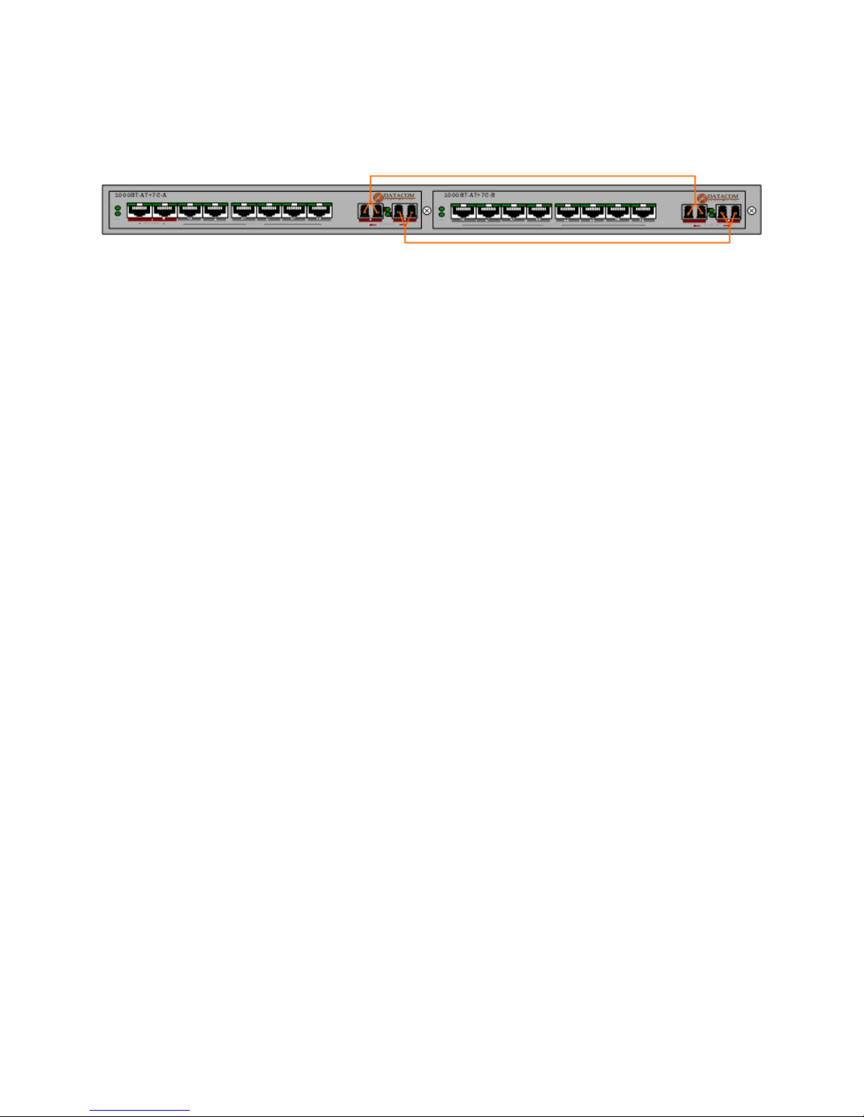
The TAP consists of two units – A and B – which are connected together via fiber ports. Unit A contains
the copper Gigabit tap assembly and the first three sets of Monitor ports. Unit B contains the remaining
four sets of Monitor ports.
The data path for both the Rx and Tx copies between the Unit A and Unit B is provided by means of two
short SX (multi-mode) fiber jumpers which are included with the device. If these fiber pairs are ever
replaced it is mandatory that 62.5 micron SX multi-mode fiber be used. Connectivity must be from “A Out”
of the A unit to “A In” of the B unit and from “B Out” of the A unit to “B In” of the B unit.
1. CONNECTING THE LINK
1. Install assembly in rack – do not connect power supplies initially
2. Disconnect the existing Cat 5 or higher cable from one of the endpoint devices of the link to be
tapped. Reconnect that cable to the Network A Port.
3. Connect the remaining endpoint device to the Network B port using an additional Cat 5 or higher
cable of appropriate length.
4. Check the two endpoint device to verify that they have established link with one another through the
unpowered tap. If link has not been established then reverse the position of the connections on
Network A and B. The cable end presently connected to Network A should be moved to Network B
and vice versa. Do not change the cable connections where they connect to the endpoint devices.
2. VERIFYING POWER FAULT TOLERANCE
2.1 Connect the four power supplies. They are load sharing devices and although only one power supply
is required for unit A and one for Unit B it is suggested for highest reliability to use all four and
connect to two separate AC grids per unit. The power indicators labeled 1 and 2 on front panels of
both units should be illuminated if power supplies are functional and properly connected.
Page 2

2.2 Upon applying power the traffic on the link will be momentarily interrupted as the endpoint devices
SYMPTOM
POSSIBLE CAUSES AND SOLUTIONS
Link stops passing data when
power to A unit is lost
Passive bypass is directional – try reversing position of cables in
Network A and Network B.
No link on endpoints of
tapped link
Tap assembly is for 1000 Mbps links only – verify that endpoint
devices are both 10/100/1000 capable and set to Auto or fixed.
Tools on A unit see data but
tools on B do not see data
Confirm that B unit has power and confirm that A Out and B Out
fiber ports of A unit are properly connected to the A In and B In
ports of B unit – also check that green link lights are illuminated
and flashing to indicate passing of data.
Link is functioning properly
but no data is visible to any of
the tools on A unit or B unit
Check to ensure that at least one functioning power supply is
connected to each of the two units and that the appropriate
green power indicators on front panel are illuminated.
Tools on B unit see only one
side of conversation
Verify that the A Out and B Out fiber ports of A unit are properly
connected to the A In and B In ports of B unit and confirm that
green link lights are illuminated.
establish link with the Network A and B ports of the powered tap. Check for green link lights on the
Network A and B ports. These lights should flash to indicate activity if data is passing on the link.
2.3 Once valid link has been established the proper functionality of the power fault tolerance feature must
be tested. Disconnect the power supplies from Unit A and check for link light on the endpoint devices
of the link to confirm that they have re-established link with one another through the passive tap.
2.4 When Unit A is powered up or down a momentary interruption of link always occurs as the relay
based power fault tolerance system moves to a closed position to provide a passive non-powered
bypass or moves back out of position to once again allow data to pass through the powered tapping
circuit. This interruption may be reduced to the shortest possible duration by setting the endpoint
devices to Port Fast, Fast Learn or an equivalent setting.
3. CONNECTING MONITORING TOOLS
3.1 Before connecting the tools first verify that the fiber jumper cables between Unit A and Unit B are
properly connected and showing link when power has been applied. Green link lights should appear
adjacent to the A Out and B Out ports of Unit A as well as the A In and B In ports of Unit B.
3.2 Using a Cat 5 or higher cable of appropriate length connect the 1-A Monitor port to the appropriate
monitor / capture card of a monitoring tool or data collection device. Using a second cable connect
the 1-B Monitor port to an additional monitor / capture card on the same tool or device.
3.3 Verify link by checking for a green light adjacent to each tap Monitor port and also on the tool or
device to which it is connected. If data is passing on the tapped link these light should blink to
indicate the presence of activity
3.4 Additional validation of proper installation should be provided by checking the attached monitoring
tool or device for the presence of data packets from both the Rx and Tx sides of the tapped link.
3.5 Additional monitoring tools or devices should be connected to the remaining Monitor ports using the
same procedures.
Congratulations - the installation is now complete!
TROUBLESHOOTING
 Loading...