

Page 1
Datacom Systems Inc
Access Your Network
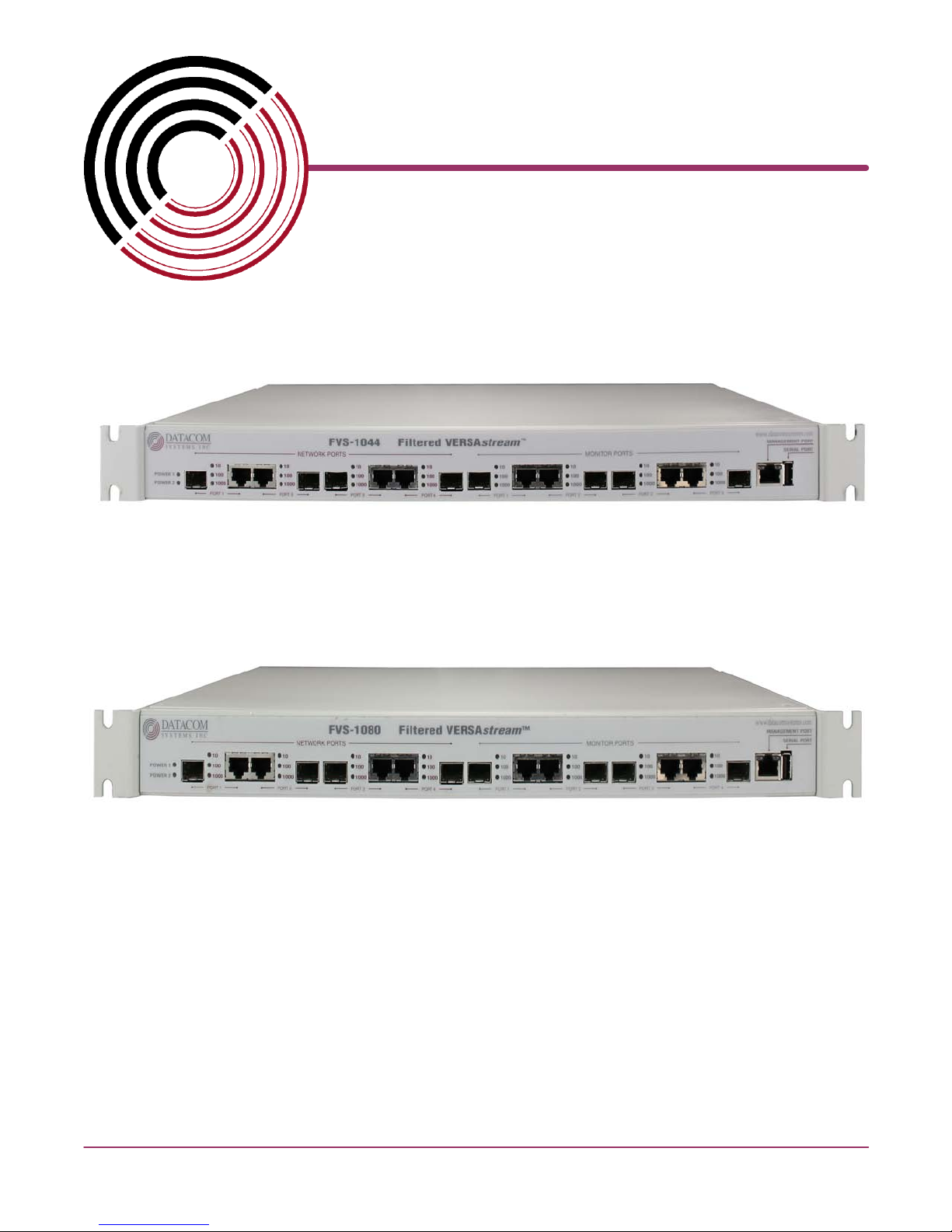
FVS-1044 Data Access Switch
TM
FVS-1080 Data Access Switch
May 2010
USER
© 2010 Datacom Systems Inc
guide
541-0114-U-B.00
Page 2

This page intentionally left blank
Page 3

Product Description
Datacom Systems Inc. Filtered VERSAstream™ Data Access Switches are
made to be adaptable. The Filtered Data Access Switch introduces line-rate
filtering that provides you with the ability to eliminate unwanted traffic from your
analysis tools or security sensors. With less data to work with through filtering,
network devices can run faster and more efficiently, which can reduce or
eliminate the possiblity of port oversubscription.
The Filtered VERSAstream™ product provides you with unprecedented
flexibility and filtering capability for your network monitoring needs offering a
complete view of the traffic and easily lets security and analysis tools collect all
the data they need, expanding network visibility.
Page 4

VERSAstream™
© 2010 Datacom Systems Inc
All rights reserved. No parts of this work may be reproduced in any form or by any means - graphic, electronic, or
mechanical, including photocopying, recording, taping, or information storage and retrieval systems - without the written
permission of the publisher.
Products that are referred to in this document may be either trademarks and/or registered trademarks of the respective
owners. The publisher and the author make no claim to these trademarks.
While every precaution has been taken in the preparation of this document, the publisher and the author assume no
responsibility for errors or omissions, or for damages resulting from the use of information contained in this document or
from the use of programs and source code that may accompany it. In no event shall the publisher and the author be liable
for any loss of profit or any other commercial damage caused or alleged to have been caused directly or indirectly by this
document.
Printed: June 2010 in East Syracuse, New York
Printed: June 2010 in East Syracuse, New York
Page 5

Table of Contents
5Table of Contents
Section 1 Terms of Use
Section 2 Overview
Section 3 Hardware
.................................................................................................... 9
........................................................................................ 91 Copyright
........................................................................................ 92 License Agreement
........................................................................................ 93 Trademark Attribution
........................................................................................ 94 Proprietary Notice
........................................................................................ 105 Certifications and Marks
........................................................................................ 106 Safety Notices and Warnings
.................................................................................................... 11
........................................................................................ 111 Shipped Contents
........................................................................................ 122 FVS Features and Benefits
........................................................................................ 133 FVS-1044 Specifications
........................................................................................ 144 FVS-1080 Specifications
.................................................................................................... 15
........................................................................................ 151 Power
........................................................................................ 152 Any-to-Any Ports
........................................................................................ 163 Management Port
........................................................................................ 164 Serial USB
........................................................................................ 165 Rear Panel
Section 4 Initial Configuration
Section 5 Hardware Installation
Section 6 FVS Application
Section 7 FLOWcontrol™
.................................................................................................... 17
........................................................................................ 171 SERIAL Port Configuration
........................................................................................ 172 IP Address
........................................................................................ 193 Small Form-Factor Plug Module
1 Installation Prerequisites
2 Safety Guidelines
3 Installing the SFP Module
4 Removing the SFP Module
...................................................................................................... 19
...................................................................................................... 19
...................................................................................................... 20
...................................................................................................... 20
.................................................................................................... 21
........................................................................................ 211 Power
........................................................................................ 212 Management Connection
........................................................................................ 223 Any-to-Any Connection
.................................................................................................... 23
.................................................................................................... 24
........................................................................................ 241 Introduction
© 2010 Datacom Systems Inc
VERSA™stream
Page 6

Table of Contents6
1 Supported Products
2 PC Requirements
3 Installation
...................................................................................................... 25
...................................................................................................... 26
...................................................................................................... 26
........................................................................................ 272 FLOWcontrol™ User Interface
1 FLOWcontrol Main Screen
1 Pull Down Menu Bar
...................................................................................................... 27
..................................................................................................... 27
........................................................................................................................................ 28
1 File
........................................................................................................................................ 29
2 Agent
.................................................................................................................................. 29
1 Connect
.................................................................................................................................. 30
2 Disconnect
.................................................................................................................................. 30
3 Communications Console
.................................................................................................................................. 30
4 Add
.................................................................................................................................. 31
5 Delete
.................................................................................................................................. 31
6 Modify
.................................................................................................................................. 31
7 Refresh
.................................................................................................................................. 31
8 Restart
.................................................................................................................................. 31
9 Agent > Add, Modify Properties Form
........................................................................................................................................ 32
3 Utilities
........................................................................................................................................ 34
4 Tabs
........................................................................................................................................ 34
5 Help
.................................................................................................................................. 34
1 About
.................................................................................................................................. 34
2 FLOWcontrol Help
.................................................................................................................................. 35
3 Web Site
.................................................................................................................................. 35
4 Tutorials
2 Agent List
2 Filter Management
1 Saved Filters Panel
2 Filter Specifics Panel
..................................................................................................... 35
...................................................................................................... 36
..................................................................................................... 37
..................................................................................................... 38
........................................................................................................................................ 39
1 Include/Exclude Definition
........................................................................................................................................ 39
2 Include VLAN Tunneling Frames
........................................................................................................................................ 40
3 Rule Definition
........................................................................................................................................ 41
4 Combinatorial Logic
........................................................................................................................................ 44
5 MAC Address Filter
........................................................................................................................................ 44
6 VLAN ID Filter
........................................................................................................................................ 44
7 IPv4 IP Address Filter
........................................................................................................................................ 45
8 IPv4 PORT Number Filter
........................................................................................................................................ 45
9 IPv6 IP Address Filter
........................................................................................................................................ 46
10 Advanced Filter
........................................................................................................................................ 47
11 Context Menus
VERSA™stream
© 2010 Datacom Systems Inc
Page 7

7Table of Contents
........................................................................................................................................ 47
12 Value Specifications
3 Advanced Filter Wizard
3 Communications Console
1 Pull Down Menus
2 Console Main Screen
4 Product Control
1 Product Control Tabs
..................................................................................................... 48
........................................................................................................................................ 51
1 MAC Address Wizard
........................................................................................................................................ 53
2 VLAN ID Wizard
........................................................................................................................................ 54
3 ETHERtype Wizard
........................................................................................................................................ 55
4 IPv4 IP Address Wizard
........................................................................................................................................ 56
5 IPv4 Protocol Wizard
........................................................................................................................................ 57
6 IPv4 PORT Number Wizard
...................................................................................................... 59
..................................................................................................... 59
..................................................................................................... 60
...................................................................................................... 60
..................................................................................................... 61
........................................................................................................................................ 61
1 Configuration Summary
.................................................................................................................................. 62
1 Filtered SINGLEstream Summary
.................................................................................................................................. 62
2 Filtered VERSAstream Summary
........................................................................................................................................ 62
2 Counter Resets
........................................................................................................................................ 63
3 Summary Expanded
........................................................................................................................................ 64
4 Port Configuration
........................................................................................................................................ 66
5 Aggregation Configuration
.................................................................................................................................. 67
1 Example Filtered SINGLEstream
.................................................................................................................................. 69
2 Example Filtered VERSAstream
5 Filter Configuration
6 Event Log
Section 8 Appendix 1 - Command Line Interface (CLI)
.................................................................................................... 73
...................................................................................................... 71
...................................................................................................... 72
........................................................................................ 731 Basic Functionality
........................................................................................ 732 Basic Command Set
1 HELP (?)
2 CLEAR LOG (CL LOG)
3 PASSWORD
4 SHOW (SH)
5 SHOW DAEMON (SH DN)
6 SHOW MANAGEMENT (SH MA)
7 SHOW NTP (SH NTP)
8 SHOW TIME (SH TI)
9 SHOW PORT STATS (SH PO ST)
10 SHOW PRODUCT (SH PR)
11 SET BAUD (SE BD)
12 SET FTP (SE FP)
...................................................................................................... 73
...................................................................................................... 74
...................................................................................................... 74
...................................................................................................... 75
...................................................................................................... 75
...................................................................................................... 76
...................................................................................................... 76
...................................................................................................... 76
...................................................................................................... 76
...................................................................................................... 77
...................................................................................................... 77
...................................................................................................... 77
© 2010 Datacom Systems Inc
VERSA™stream
Page 8

Table of Contents8
13 SET DEFAULT IP (SE DEF IP)
14 SET IP (SE IP)
15 SET SUBNET (SE SU)
16 SET GATEWAY (SE GA)
17 SET PORT (SE PO)
18 SET NTP (SE NTP)
19 SET PING (SE PG)
20 SET SSH (SE SH)
21 SET SYSLOG (SE SY)
22 SET TELNET (SE TT)
23 SET TFTP (SE TP)
24 SET TIME (SE TI)
25 REBOOT
26 REBOOT -management
27 EXIT
Section 9 Appendix 2 - Sample Filter Setup
Section 10 Customer Service
.................................................................................................... 84
.................................................................................................... 88
...................................................................................................... 78
...................................................................................................... 78
...................................................................................................... 79
...................................................................................................... 79
...................................................................................................... 80
...................................................................................................... 80
...................................................................................................... 81
...................................................................................................... 81
...................................................................................................... 81
...................................................................................................... 81
...................................................................................................... 82
...................................................................................................... 82
...................................................................................................... 82
...................................................................................................... 83
...................................................................................................... 83
........................................................................................ 881 World Wide Web
........................................................................................ 882 Warranty
........................................................................................ 893 Limits of Liability
........................................................................................ 894 Force Majeure
VERSA™stream
© 2010 Datacom Systems Inc
Page 9

Terms of Use
9
1 Terms of Use
The following terms and conditions relate to the use of this document. Please note that Datacom Systems Inc.
reserves the right, at its entire discretion, to change, modify, add, or remove portions of these Terms of Use at
any time. Please read the Terms of Use carefully as your use of this document is subject to the Terms of Use
stipulated herein.
1.1 Copyright
Copyright© 2007-2010 by Datacom Systems, Inc. All rights reserved. Printed in the United States of America.
No part of this publication may be reproduced, stored in a retrieval system, or transmitted, in any form or by
any means, electronic, mechanical, photocopying, recording, or otherwise, without the prior written permission
of Datacom Systems, Inc. To obtain this permission, write to the attention of the Datacom Systems legal
department at 9 Adler Drive, East Syracuse, New York 13057-1290, or call 315-463-9541.
1.2 License Agreement
Notice To All Users: By using Datacom Systems, Inc. products, you agree to the terms set forth. No licenses,
express or implied, are granted with respect to the technology described and Datacom Systems, Inc. retains all
rights with respect to the technology described herein. If applicable, you may return the product to the place of
purchase for a full refund.
1.3 Trademark Attribution
Access Your Network , DS3 ACTIVEtap , DS3switch , DURAstream , ETHERNETtap , Empowering
Network Professionals , FDDIswitch , FIBERsplitter , FIBERswitch , FIBERSWITCHsystem , FLOW
control , GIGABITswitch , INSERTswitch , INSERTunit , LANswitch , MANAgents ,
MULTINETswitch , NETspan , PERMAlink , PROline , RMON SWITCHINGanalyzer , SINGLE
stream , UNIVERSALswitch , VERSAstream , and WANswitch are trademarks of Datacom Systems,
Inc. 1ST in Switching Solutions®, DATACOMsystems®, LANclipper®, MANAgents®, and MULTIview® are
registered trademarks of Datacom Systems, Inc. All other registered and unregistered trademarks are the sole
property of their respective owners. All specifications may be changed without notice.
1.4 Proprietary Notice
This document contains proprietary information about the filtered product family of products and is not to be
disclosed or used except as authorized by written contract with Datacom Systems, Inc.
© 2010 Datacom Systems Inc
VERSA™stream
Page 10
1.5 Certifications and Marks
CAUTION: Changes or modifications to this unit not expressly approved by the party responsible for
compliance could void the user’s authority to operate the equipment.
The CE logo indicates that this equipment was tested and found to meet radiated and
conducted emission to the European Community EMC Directive 89/336/EEC requirements as
per EN 61000-6-3:2001, the generic emissions standard for residential, commercial and light
industrial devices, the limits are those for an EN 55022 Class A product.
This equipment also has been tested and found to meet the immunity levels for residential, commercial and
light industrial devices according to EN 61000-6-1:2001, the interference severity levels to the standards
and requirements of EN 61000-3-2 Harmonic Current, EN 61000-3-3 Voltage Fluctuations and Flicker,
EN 61000-4-2 Electrostatic Discharge, EN 610004-3 Radiated Susceptibility, EN 61000-4-4 Electrical
Fast Transient/Burst, EN 61000-4-5 Surge and EN 61000-4-6 Conducted Susceptibility.
This equipment completed the Product Safety Review and meets the Low Voltage Directive 98/68/EEC
requirements to the standards of EN 60950 Safety of Information Technology Equipment.
The RoHS compliant logo indicates that this electronic product does not exceed the limit
requirements of toxic, hazardous substances or elements as set forth in Directive 2002/95/EC
of the European Parliament and of the Council of 27 January 2003 on the restriction of the use
of certain hazardous substances in electrical and electronic equipment.
The crossed out wheelie bin logo signifies that the product can be recycled after being
discarded, and should not be casually discarded as set forth in Directive 2002/96/EC of the
European Parliament and of the Council of 27 January 2003 on waste electrical and electronic
equipment (WEEE).
These explanatory labels are included in this information for the user in accordance
with the requirements of IEC 60825.1.
WARNING: Class 1 laser and LED product. A class 1 laser is safe under all
conditions of normal use. Invisible laser radiation may be emitted from optical
port openings when no fiber cable is connected, avoid exposure to laser
radiation and do not stare into open optical ports.
Terms of Use10
1.6 Safety Notices and Warnings
VERSA™stream
© 2010 Datacom Systems Inc
Page 11

Overview
11
2 Overview
The Filtered VERSAstream™ (FVS) product line increases network visibility and leverages your investment in
network analyzers, probes, and security equipment by allowing you to simultaneously monitor as many
supported ports as you may need to fit your peripheral network tools. Greater visibility accelerates problem
resolution, reduces downtime and increases enterprise productivity.
Like all Datacom Systems filtered products, the FVS-1044 and FVS-1080 filtered products are compatible
with all vendor hardware and can be controlled by our FLOWcontrol software, which will allow you to
control your filtered product line through a single interface regardless of what network appliances you choose to
deploy.
The Filtered VERSAstream™ product line gives you access to your network without creating bottlenecks by
providing the capability to monitor, aggregate and filter network traffic to an analysis device or sensor.
Aggregation combines two or more streams of network traffic into one link. Aggregated network traffic may
overload or oversubscribe an analysis device. Filtering unwanted network traffic reduces the potential for
oversubscribing. The Filtered VERSAstream™ product line features hardware based, line-rate filtering. This
allows you to eliminate unwanted network traffic from analysis tools or sensors. Filtering also gives you the
ability to deploy lower speed tools on higher speed networks.
2.1 Shipped Contents
FVS-1044 filtered product
1 — Model: FVS-1044
2 — AC Line Cords
1 — FLOWcontrol™ software
1 — DRL434-6-R cable, USB type A to DB9 F
1 — DRL366-3-R cable, RJ45 to RJ45
FVS-1080 filtered product
1 — Model: FVS-1080
2 — AC Line Cords
1 — FLOWcontrol™ software
1 — DRL434-6-R cable, USB type A to DB9 F
1 — DRL366-3-R cable, RJ45 to RJ45
© 2010 Datacom Systems Inc
VERSA™stream
Page 12

2.2 FVS Features and Benefits
Apply port level packet filtering to SPAN monitoring solutions.
Line-rate filtering eliminates unwanted traffic from analysis tools or security sensors.
Load balancing eliminates bottlenecks and port over subscription.
Filter network traffic to any monitoring port based upon IP address, port number, MAC address,
VLAN, protocol type or customizable offsets in the IP header.
"Any-to-Any" architecture can send traffic from any input ports to any monitoring ports.
"Many-to-Any" architecture combines traffic from up to four of the input ports, providing visibility into
multiple network segments with one monitoring tool.
"One-to-Many" architecture allows sending multiple copies of data from the input port to multiple
monitoring devices.
Aggregate and reassembly full duplex conversations from multiple trunk links, redundant networks,
Ether Channel, load balanced servers and asymmetrically routed traffic.
Overview12
Simultaneously monitor data at multiple points on the network with the same set of devices.
Datacom Customer Service Support is available via:
Phone: (315) 463-9541
Fax: (315 ) 463-9557
E-mail: support@datacomsystems.com
Website: www.datacomsystems.com
VERSA™stream
© 2010 Datacom Systems Inc
Page 13

Overview
2.3 FVS-1044 Specifications
Network Ports (front):
4 - 10/100/1000BaseT (RJ45 Connectors) or SFP*
*SFP = Small Form Pluggable can be LX or SX
Monitor Ports (front):
4 - 10/100/1000BaseT (RJ45 Connectors) or SFP*
*SFP = Small Form Pluggable can be LX or SX
Management Port (front):
RJ45 @ 10/100 Mbs Full-Duplex
Serial Port (front):
USB-type A style
Power:
Input: 120-240VAC 50-60Hz, 0.6A-0.3A
13
Dimensions (H x W x D): includes mount bracket
1.75 x 19.00 x 12.00 inch
4.44 x 48.26 x 30.48 cm
Weight:
7.0 lbs; shipping: 14.0 lbs
3.175 kg; shipping; 6.3 kg
Operating Temperature:
32º to 104° F
0º to 40° C
Storage Temperature:
-22º to 149° F
-30º to 65° C
Humidity:
Less than 95° C non-condensing
Warranty:
One (1) year - see 'Warranty' section for details.
88
© 2010 Datacom Systems Inc
VERSA™stream
Page 14

2.4 FVS-1080 Specifications
Network or Monitor Ports (front):
8 - 10/100/1000BaseT (RJ45 Connectors) or SFP*
*SFP = Small Form Pluggable can be LX or SX
Management Port (front):
RJ45 @ 10/100 Mbs Full-Duplex
Serial Port (front):
USB-type A style
Power:
Input: 120-240VAC 50-60Hz, 0.6A-0.3A
Dimensions (H x W x D): includes mount bracket
1.75 x 19.00 x 12.00 inch
4.44 x 48.26 x 30.48 cm
Weight:
7.0 lbs; shipping: 14.0 lbs
3.175 kg; shipping; 6.3 kg
Overview14
Operating Temperature:
32º to 104° F
0º to 40° C
Storage Temperature:
-22º to 149° F
-30º to 65° C
Humidity:
Less than 95° C non-condensing
Warranty:
One (1) year - see 'Warranty' section for details.
88
VERSA™stream
© 2010 Datacom Systems Inc
Page 15
Hardware
15
3 Hardware
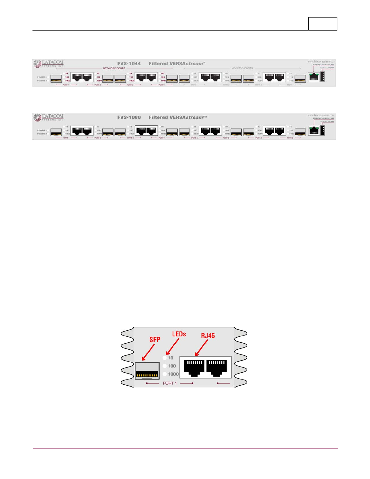
This section provides an illustration and description of the FVS series product:
FVS-1044
FVS-1080
An explanation of each front panel legend follows:
3.1 Power
Two AC power sources are provided for the filtered product unit. Although only one power source is required
to power the module, use of a second independent power source is strongly recommended to assure
uninterrupted monitoring. Furthermore, connecting the second AC input power socket to a different external
power source circuit than the first AC input power source eliminates power as a single point of failure. The
power sockets are located on the rear.
The POWER 1 and 2 front panel LEDs illuminate green when power is available at both of the two rear power
sockets indicating power 1 and 2, respectively, are on. Either LED not illuminated indicates immediate
investigation is recommended if both power sources are being used and a power led is not illuminated to insure
redundant power integrity.
3.2 Any-to-Any Ports
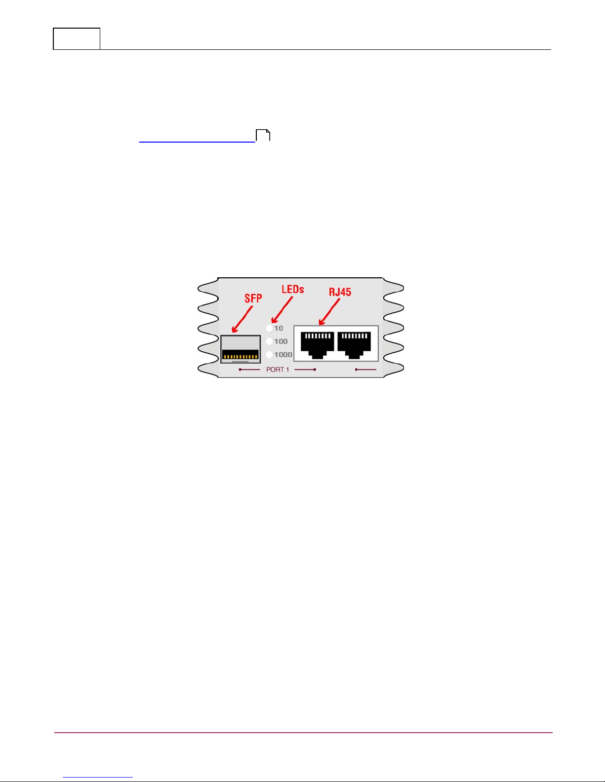
SFP or RJ45 — SFPare Small Form Pluggable (can be LX or SX) or RJ45 are RJ45 connectors used for
connection to network segments or analysis tools. Between the connectors are LEDs that display line status and
line speed of each port. A solid light indicates the Fiber SFP or RJ45 10/100/1000BaseT port is connected. A
blinking light indicates the presence of traffic.
© 2010 Datacom Systems Inc
VERSA™stream
Page 16
Hardware16
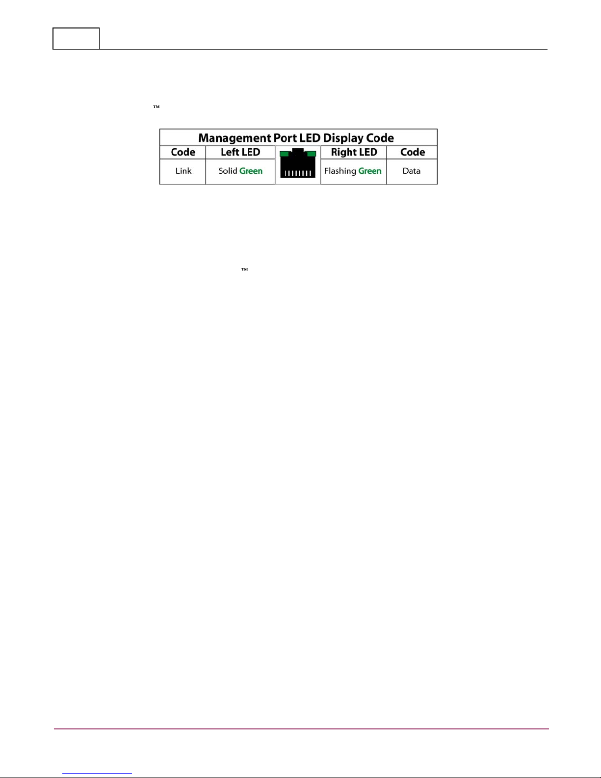
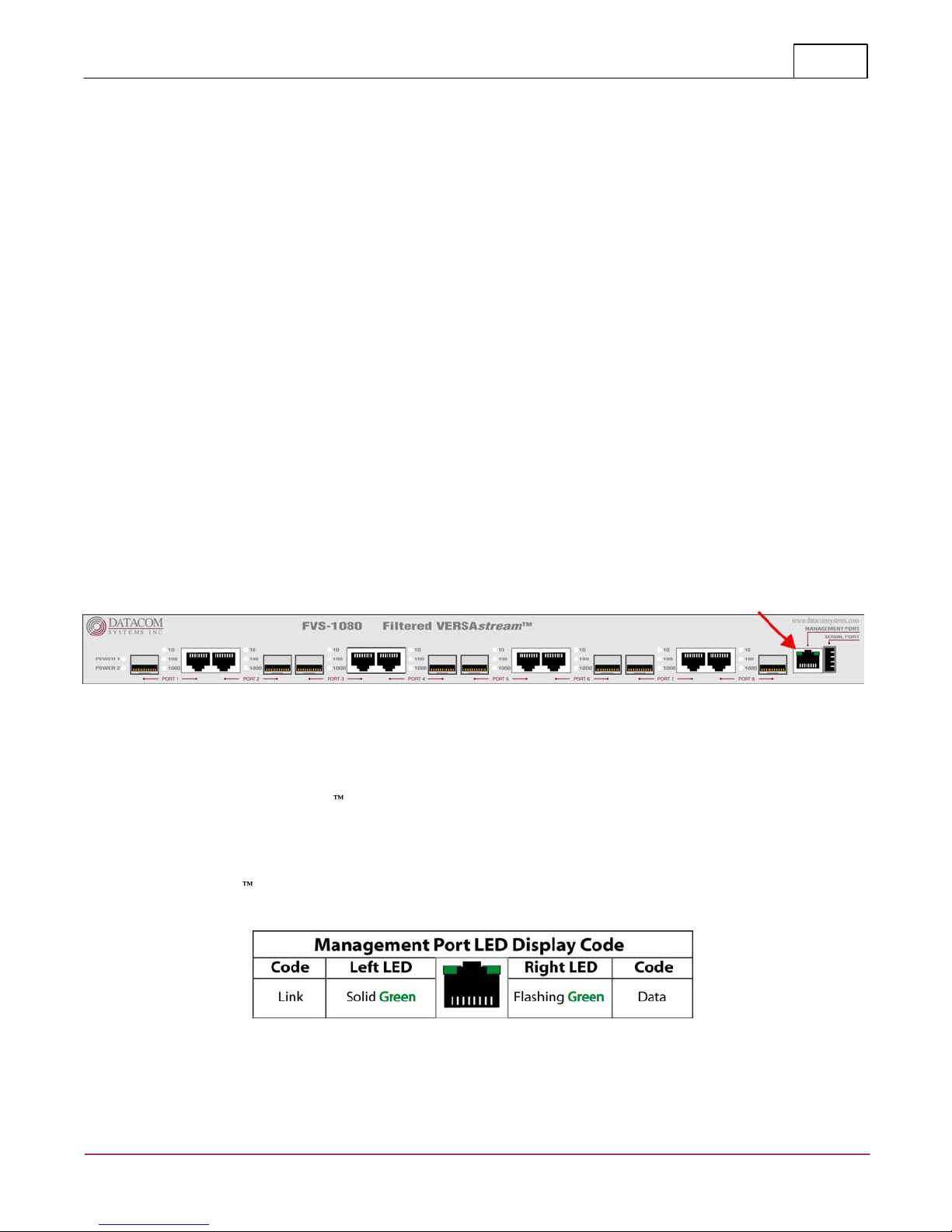
3.3 Management Port
The MANAGEMENT PORT is an RJ45 socket used for 10/100 Mbs fixed full-duplex connection with a straightthrough LAN cable via your management LAN to a Remote Management Console which is a standard PC
running FLOWcontrol .
Link indicates connection. The LED Display Code table deciphers the RJ45 jacks with integrated LEDs that
display line status of the MANAGEMENT PORT.
3.4 Serial USB
The SERIAL connector port is a shielded USB type A Female and is cabled to the COM port of any compatible
network tool or PC where FLOWcontrol Software resides. It is the only port that can easily connect the
Management PC to set the IP address for the first time.
3.5 Rear Panel
Two AC input power sockets are provided on the rear panel.The POWER 1 and 2 front panel LEDs illuminate
green when power is available at both of the two rear power sockets indicating power 1 and 2, respectively,
are on. Either front panel LED not illuminated indicates immediate investigation is recommended if both power
sources are being used and a power led is not illuminated to insure redundant power integrity.
Although only one AC power source is required to power the filtered product unit, use of a second independent
power source is strongly recommended to assure uninterrupted monitoring. Furthermore, connecting the second
AC input power socket to a different external power source circuit than the first AC input power source
eliminates power as a single point of failure.
VERSA™stream
© 2010 Datacom Systems Inc
Page 17

Initial Configuration
FVS-1044
FVS-1080
2400 bits per second
9600 bits per second
8 data bits
8 data bits
Parity none
Parity none
1 stop bit
1 stop bit
Flow control none
Flow control none
17
4 Initial Configuration
IMPORTANT: Review the following section prior to initial configuration of the hardware.
IMPORTANT: Detailed Command Line Interface (CLI) syntax information is found in the 'Appendix
1 - Command Line Interface (CLI) ' section.
Initial configuration is performed directly with a terminal emulation application on a management PC connected
to the FVS through the SERIAL USB-style type A port. After initial configuration, the FVS can be remotely
operated though the MANAGEMENT RJ45 port. Only one configuration session can be open at a time.
4.1 SERIAL Port Configuration
Once the FVS SERIAL port hardware connection is made, open the terminal emulator application on the
management PC and create a connection with the settings that fit your needs:
73
4.2 IP Address
All FVS filtered products are assigned an IP address (192.168.1.1) by default. You must change the IP
address to match your network.
NOTE: If your FVS already has an IP address for your network, you may proceed to the 'Small Form-Factor
Plug Module ' section.
Step 1. First, connect your terminal emulator application PC and FVS using the provided Datacom Systems
DRL434-6-R cable. Connect the DB9 Female pin end to the serial port on your PC and connect the USBstyle Type A end to the SERIAL port on the unit.
Step 2. Open the terminal emulator application on your PC.
Step 3. Create a serial link by selecting the COM port assigned to the serial port on your PC.
Step 4. Next, configure the COM Properties. The initial correct setting to communicate with the FVS series
product (9600, 8, None, 1, None) are shown below. Once all settings are configured correctly, you can
connect to your Filtered VERSAstream™ product.
19
NOTE: For PCs without 9-pin serial ports, check with you product representative for available sources
of a USB to RS-232 Plug-in Adapter.
Step 5. Next, plug the FVS into the external power source using the supplied AC line cord. Note that either
POWER 1 or 2 LED is illuminate green indicating power is available at the rear AC power socket to which the
AC Line Cord is connected. The other POWER LED is not illuminated, indicating a lack of power to the
unconnected AC power socket.
© 2010 Datacom Systems Inc
VERSA™stream
Page 18

Initial Configuration18
Prior to proceeding any command line entry, observe the following serial startup screen activity that will last for
approximately one and a half to two minutes:
DipSwitch Status = 0xFF
Enabling Datacom RS232 serial port.
Datacom Systems, Inc. FVS-1080
Starting Self Tests.....
Memory Tests Pass!
Located Datacom 512MB DDR
*
*
*
Booting Operating System.....please wait.....
VERSAstream Initialization In Process....
Restoring Settings...
VERSAstream Active...
The FVS is now ready to accept command line entry commands.
Step 6. Hit the Enter key twice in succession (i.e., Enter, Enter) to display the username: prompt. The CLI
username and password are case-sensitive. The default values are:
username: Administrator
password: admin
> ? and press the Enter key to see available commands list, details in 'Basic Command Set ' section.
73
Step 7. Separate IP, Subnet or Gateway CLI entries ARE NOT ALLOWED for the FVS-1080. 'Set IP
Address ' by typing SET IP ppp.ppp.ppp.ppp sss.sss.sss.sss ggg.ggg.ggg.ggg where ppp.ppp.ppp.ppp
78
corresponds to a valid IP address, where sss.sss.sss.sss corresponds to a valid SUBNET for your network and
where ggg.ggg.ggg.ggg corresponds to a valid GATEWAY for your network. Press the Enter key to continue.
Step 8. Review and verify the network address settings are correct and enter (y) to confirm changes (updating
elapsed time approximately 15 seconds) otherwise enter (n) to cancel and repeat Step 7.
Step 9. Follow the screen prompts and at the command prompt, type 'REBOOT -management ' to allow the
83
new network setting to take effect.
Step 10. Follow the screen prompts and after the screen response VERSAstream Active . . . (elapsed time
approximately 35 seconds) type 'SH MA ' to review the network address settings. Verify settings are correct.
76
Step 11. Type 'EXIT ' and press the Enter key to end the connection session indicated by 'Closing
83
Connection . . . ' response, then close the terminal emulation application.
Step 12. Disconnect the DRL512-2M-R serial cable from your FVS series product and proceed to install the
FVS series product in your chosen network location.
VERSA™stream
© 2010 Datacom Systems Inc
Page 19

Initial Configuration
19
4.3 Small Form-Factor Plug Module
This section provides information about small form-factor plug (SFP) modules. The SFP modules are input/
output devices that plug into a Gigabit Ethernet (GE) small form-factor (SFF) port, linking the port with a
1000Base-X fiber.
The fiber SFP module have a receiver port (Rx) and a transmitter port (Tx) that make up one optical interface.
The 1000Base-SX (short wavelength) SFP module operates on standard multimode fiber networks compliant
with the 1000Base SX standard. The 1000Base-LX (long wavelength) SFP module operates on standard
single-mode fiber networks compliant with the 1000Base LX standard. The fiber SFP module is a 1000 Mbps
optical interface in the form of an LC-type duplex port that supports interfaces compliant with the 1000Base-X
standard.
4.3.1 Installation Prerequisites
This section describes safety and compliance guidelines you should observe before you install an SFP module in
your FVS unit.
NOTE: You can install and remove SFP modules with power on to the system; however, it is strongly
recommended that you do not install or remove the SFP module with fiber or copper cables attached to it.
Disconnect all cables before removing or installing a SFP module.
CAUTION: Prevent system problems, use only Datacom Systems Inc. supplied SFP modules.
4.3.2 Safety Guidelines
Before handling a SFP module, observe the following guidelines:
Copper and fiber SFP modules are static-sensitive. To prevent electrostatic discharge (ESD) damage, follow
your normal ESD handling procedures.
Fiber SFP modules are dust-sensitive. When storing a SFP module or when a fiber cable is not plugged in,
always keep plugs in the SFP module optical hole.
The most common source of contaminants in the fiber SFP optical aperture is debris picked up on the
terminations of the optical connectors. Use an alcohol swab or lint-free absorbent wipes to clean the
terminations of the optical connector.
WARNING: Fiber SFP modules are class 1 laser and LED products. Invisible laser radiation may be
emitted from the port opening when no fiber cable is connected, avoid exposure to laser radiation and
do not stare in open optical ports.
© 2010 Datacom Systems Inc
VERSA™stream
Page 20

Initial Configuration20
4.3.3 Installing the SFP Module
SFP modules might ship already installed in your FVS or they might arrive packaged separately. This section
describes how to install the SFP module.
NOTE: You can install SFP modules with power on to the system; however, it is strongly recommended that
you do not install the SFP module with fiber or copper cables attached to it. Disconnect all cables before
installing a SFP module.
CAUTION: Prevent system problems, use only Datacom Systems Inc. supplied SFP modules.
Step 1. Turn the SFP module so the latch is towards the center of the Gigabit Ethernet Interface sockets. The
SFP module is keyed so that it cannot be inserted incorrectly.
Step 2. Insert the SFP module into the SFF port and repeat Step 1 and Step 2 inserting other SFP modules
until completed.
Step 3. Attach the appropriate network cable to the LC-type or RJ45-type connector on the SFP module. For
fiber optic SFP modules you can use either simplex or duplex connectors. For simplex connectors, two cables
are required, one cable for transmit (Rx) and a second cable for receive (Rx). For duplex connectors, only one
cable that has both Tx and Rx connectors is required.
4.3.4 Removing the SFP Module
SFP modules might ship already installed in your FVS or they might arrive packaged separately. This section
describes how to remove the SFP module.
NOTE: You can remove SFP modules with power on to the system; however, it is strongly recommended that
you do not remove the SFP module with fiber or copper cables attached to it. Disconnect all cables before
removing a SFP module.
Step 1. Disconnect the network cable from the SFP module LC-type or RJ45-type connector.
Step 2. Release the SFP module from the GE SFF port by moving the swing latch away from the body of the
unit.
Step 3. Slide the SFP module out of the GE SFF port.
VERSA™stream
© 2010 Datacom Systems Inc
Page 21
Hardware Installation
21
5 Hardware Installation
This section specifically describes the FVS-1080 hardware installation at the network site of your choice. The
FVS-1044 is similar in functionality and the same basic installation procedure may be used as a guide during
FVS-1004 installation.
5.1 Power
This section describes the installation site power connection of the FVS-1080 at the network site.
Two AC input power sockets are provided on the rear panel. The front panel POWER 1 and 2 LEDs are
illuminated green, respectively when AC power is available at both the two rear AC power sockets.
Either POWER 1 or 2 LED not illuminated when powered, indicates a defective power source and immediate
investigation as to the cause is required to insure redundant power integrity.
Step 1. Using the supplied AC Line Cords, plug the FVS-1080 series product into different circuit external
power sources. Although only one external power source is required to power the unit, use of a second
independent external power source is strongly recommended to assure uninterrupted monitoring. Furthermore,
connecting to a second different external power source circuit than the first AC power source eliminates power
as a single point of failure.
5.2 Management Connection
This section shows the MANAGEMENT port 100 Mbs fixed full-duplex connection of the typical FVS-1080
hardware installation.
Step 1. Connect a network cable to the MANAGEMENT port RJ45 socket. The MANAGEMENT port RJ45 left
LED illuminates green when link has been established with the network. The MANAGEMENT port right LED
illuminates green when passing data.
Step 2. Refer to the FLOWcontrol help file for detail operation of the FVS-1080 filtered product.
The MANAGEMENT PORT is an RJ45 socket used for 100 Mbs fixed full-duplex connection with a straightthrough LAN cable via your management LAN to a Remote Management Console which is a standard PC
running FLOWcontrol .
Link indicates connection. The LED Display Code table deciphers the RJ45 jacks with integrated LEDs that
display line status of the MANAGEMENT PORT.
© 2010 Datacom Systems Inc
VERSA™stream
Page 22
Hardware Installation22
5.3 Any-to-Any Connection
This section will focus on the Any-to-Any port connection of the typical FVS-1080 hardware installation.
NOTE: For FVS-1080 with the Gigabit Ethernet (GE) small form-factor (SFF) ports, the SFP modules might
ship already installed in your unit, or they might arrive packaged separately. See the 'Small Form-Factor
Pluggable' section, 'Installing the SFP Module ,' on how to install the SFP module.
Step 1. Connect a network or monitoring cable to an Any-to-Any port socket and the other side of this cable to
the network or monitoring tool NIC port as appropriate..
Step 2. Continue repeating Step 1. for any remaining Any-to-Any port socket you want connected from the
FVS-1080.
Between the connectors are LEDs that display line status and line speed of each port. A solid light indicates the
Fiber SFP or RJ45 10/100/1000BaseT port is connected. A blinking light indicates the presence of traffic.
20
VERSA™stream
© 2010 Datacom Systems Inc
Page 23
FVS Application
6 FVS Application
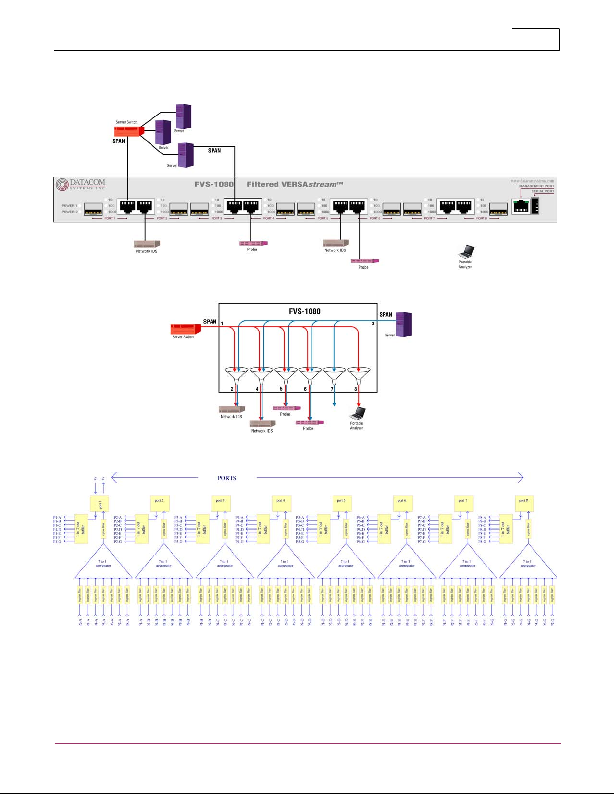
This section depicts a simple application using the Filtered VERSAstream™ FVS-1080 solution.
23
FVS-1080 Functional
© 2010 Datacom Systems Inc
VERSA™stream
Page 24

FLOWcontrol™24
7 FLOWcontrol™
FLOWcontrol™ is specifically designed for control of Filtered Products
manufactured by Datacom Systems Inc. Specific elements of the Graphical User
Interface (GUI) provide guidance in the management, configuration and
troubleshooting of Datacom Systems Inc based products.
7.1 Introduction
The Filtered Product Aggregation Tap gives you in-line access, without creating a
network bottleneck, since the tap allows all network traffic through to the far
end, but provides the ability to aggregate, regenerate and filter copies of
network traffic to specific monitoring ports.
The Filtered Product Data Access Switch allows aggregation, regeneration and
filtering with inputs from Switch Probe Analyzer (SPAN) or Port Mirror ports.
Line-rate filtering provides you the ability to eliminate unwanted traffic from
your analysis tools or security sensors. With less data to work with, network
devices run faster and more effectively, and through filtering, you can reduce or
eliminate the possibility of port oversubscribing.
Using the built-in technologies of link aggregation, regeneration, and filtering,
you can quickly and easily load balance both your network and your network
tools and eliminate bottlenecks.
Aggregation lets you load balance your network with confidence. The Filtered
Product will combine one or more full duplex streams of data from one or more
network segments, reassemble the conversation, and send an exact copy to your
connected monitoring device.
Regeneration allows you to attach more than one device to a single network
segment. Connect an analyzer and a security sensor to the same link, and you
can troubleshoot your network without having to disconnect your IDS. Add
filtering, and you can send only the data you want to each tool, improving
monitoring efficiency, speed, and network uptime.
Regeneration also allows you to connect two or more identical devices to the
same link, so you can load balance your tools. Extending the power of
regeneration with filtering, you can filter and send data to each tool based on
whatever parameter you choose (e.g. IP range). Distributing processes over
multiple tools allows them to work faster and reduces or eliminates network
bottlenecks that can be caused by slow processing of data.
VERSA™stream
© 2010 Datacom Systems Inc
Page 25

FLOWcontrol™
SS-1204LR-10G
VS-1204-10G
SS-1204SR-10G
VS-1206LR-10G
SS-1206LR-10G
VS-1206SR-10G
SS-1206SR-10G
VS-1214-10G
SS-1214LX-10G
SS-1214SR-10G
SS-1214SX-10G
FSS-1000BT
FVS-1044
SS-1204LR-10G-F
VS-1204-10G-F
FSS-1000LX
FVS-1080
SS-1204SR-10G-F
VS-1206LR-10G-F
FSS-1000SX
SS-1206LR-10G-F
VS-1206SR-10G-F
FSS-2000BT
SS-1206SR-10G-F
VS-1214-10G-F
FSS-2000LX
SS-1214LX-10G-F
FSS-2000SX
SS-1214SR-10G-F
FSS-2000BT/LX
SS-1214SX-10G-F
FSS-2000BT/SX
FTAP-1000BT
FTAP-2000BT
FASTAP-1044BT
FTAP-1000LX
FTAP-2000LX
FTAP-1000SX
FTAP-2000SX
FTAP-2000BT/LX
FTAP-2000BT/SX
7.1.1 Supported Products
FLOWcontrol™ supports these Datacom Systems Inc Products:
FLOWcontrol™ supports these Datacom Systems Inc Filter Products:
25
Also, FLOWcontrol™ supports these Fluke Networks Filtered Products:
© 2010 Datacom Systems Inc
VERSA™stream
Page 26

FLOWcontrol™26
7.1.2 PC Requirements
IMPORTANT: Update to the current Microsoft® .NET Framework before
installing FLOWcontrol™ software.
The FLOWcontrol™ software is compatible with any Windows Operating System
that supports Microsoft® .NET Framework.
7.1.3 Installation
This section installs FLOWcontrol™ software and is used to configure the Filtered
Products listed in Supported Products . You must run the setup program which
25
takes you through the installation with instructions on every screen. Copying
files directly from the distribution CD to your hard disk will result in a failed
installation. When the setup program is finished, put the CD in a safe place.
Before installing FLOWcontrol™:
Log into your Windows operating systems computer with administrator
privileges
Close all other applications before beginning the installation.
Make sure you have at least 100 MB of available disk space.
NOTE: Some computers have security protections associated with the
installation of new applications. If presented with a Security Warning, click
through to continue the installation process.
To install the FLOWcontrol™ software on your computer:
Insert the FLOWcontrol™ CD into your computer's CD-ROM drive. The
1.
installation InstallShield Wizard program should start automatically. If it
does not start, locate your CD-ROM drive in Windows Explorer and doubleclick the setup.exe program.
Follow the specific instructions on each screen to run the setup program.
2.
Read and accept the terms of the Software License Agreement.
3.
Choose either the default or an appropriate Destination Folder and click
4.
Next to begin the installation. All files needed are copied during
installation.
When InstallShield is done, before clicking the Finish button, you may
5.
optionally check the Launch FLOWcontrol box to immediately use
FLOWcontrol™ after clicking the Finish button.
NOTE: It may be necessary to open TCP Port 2370 on local Firewall settings
in the Windows 2000 / Windows XP environments in order for the
FLOWcontrol™ software to function properly. the software uses this port to
communicate with connected devices.
You are now ready to begin using FLOWcontrol™!
VERSA™stream
© 2010 Datacom Systems Inc
Page 27
FLOWcontrol™
FLOWcontrol™ Main Screen
Communications Console
Filter Management
Product Control Screen
The FLOWcontrol
Main Screen
contains three
elements. The first
is the Pull Down
Menu Bar, the
second is the
Agent List and the
third is the Filter
Management.
File
Tabs
Agent
Help
Utilities
27
7.2 FLOWcontrol™ User Interface
In order to start the FLOWcontrol™ application, use the Windows Menu
Selections by selecting: Start > Programs > Datacom Systems >
FLOWcontrol_V2
The Graphical User Interface (GUI) for FLOWcontrol™ consists of multiple
elements which will be described in the sections that follow. These include:
27 59
36 60
You may need to configure your Filtered Product with an IP address that is
appropriate for your local network before making use of the FLOWcontrol
software. Details for setting the IP address can be found in the Filtered Product
Hardware USERguide. A connection can also be established using the factory
default (192.168.1.1) IP address.
7.2.1 FLOWcontrol Main Screen
The Main Screen is shown here when FLOWcontrol™ is run the first time. From
the Main screen the user is able to connect to a Filtered Product to create a new
Agent, use an existing Agent or modify the properties of an existing Agent. After
subsequent runs of FLOWcontrol™, a short delay may be experienced while
FLOWcontrol™ loads existing Agent elements. FLOWcontrol™ supports off-line
filter management.
7.2.1.1 Pull Down Menu Bar
The FLOWcontrol™ Main Screen Pull Down Menu Bar includes a number of
sections. These include:
28 34
29 34
32
Each of these menu options may also have sub menu items. Each of the pull
down menu options are discussed in later sections.
© 2010 Datacom Systems Inc
VERSA™stream
Page 28

7.2.1.1.1 File
Selection of this sub menu will operate in one of two
ways. If no Agent connection exists, the FLOWcontrol
program exits. If a connection exists, a LOGOUT is
performed and the tab page which contains the product specific controls is
removed. All other tabs, including Filter Management, other connected
Agents, and any Communications Consoles will remain. Multiple connected
agents can be maintained within FLOWcontrol™. If the Filter Management tab
is selected when File > Exit is executed, a sequence of dialog boxes will
appear asking for confirmation to close any other Agents that may be
connected.
This first figure
represents the
unconnected
Main Screen
This second figure
represents the
Main Screen with
a single Agent
connected to a
Filtered product
(specifically an
FVS-1080).
And this third
figure represents
a Main Screen
with multiple
agents
connected.
File > Exit — The File menu option provides only an Exit option.
FLOWcontrol™28
Selection of the in the upper right of the window in either case performs the
exact same functionality as the File > Exit menu option.
VERSA™stream
© 2010 Datacom Systems Inc
Page 29

FLOWcontrol™
Connect
Disconnect
Communications Console
Add
Modify
Delete
Refresh
Restart
Agent > Connect — menu selection will
attempt to authenticate to the selected
agent. If no agent is selected, a message
box will be presented indicating that an
agent must be selected.
If the agent is a normal FLOWcontrol™ agent, a dialog box
will appear requesting authentication information for the
selected agent. The Username field of the dialog box will be
loaded with the last known User to login.
7.2.1.1.2 Agent
The Agent menu provides for context sensitive options. These include:
7.2.1.1.2.1 Connect
29
If the agent is a telnet Agent, a TELNET Communications Console will
automatically open.
© 2010 Datacom Systems Inc
VERSA™stream
Page 30

FLOWcontrol™30
Entry of a valid Username and Password will authenticate and subsequently
connect to the filtered product for which the agent was selected. During the
connection phase, the authentication of the entered Username and Password is
completed. If the authentication is valid, FLOWcontrol™ requests information
from the filtered product regarding its product properties (i.e., supported media
types, tap ports, etc.). Based upon the properties, various FLOWcontrol
elements are loaded. These elements may vary from product to product. Once
the product elements are loaded, another tab page is added which corresponds
to the product selected. A front panel graphic is presented and a series of
subordinate tab pages are populated, also based on the product properties.
In FLOWcontrol™, it is possible to connect to multiple agents simultaneously.
However, when a connection has been established, the newly connected agent's
product tab is selected.
7.2.1.1.2.2 Disconnect
Agent > Disconnect — menu selection will perform the same functionality as
the File > Exit menu option. Please refer to that section to determine the
28
functionality.
7.2.1.1.2.3 Communications Console
Agent > Communications Console — will Open or Close a specified
Communications Console. A newly created Communications Console can be used
for either Telnet or Serial communications.
Additional information regarding the Communications Console can be found in
59
the section that follows.
7.2.1.1.2.4 Add
Agent > Add — menu selection will invoke the Agent Properties form as noted in
the Agent > Add, Modify Properties Form section of this document. A new
31
Agent can be added to the Agent List using this function.
VERSA™stream
© 2010 Datacom Systems Inc
Page 31

FLOWcontrol™
Agent > Delete — menu selection will remove
an agent from the Agent List and from the
registry, where the definition for said agent
resides. A confirmation screen is presented
prior to allowing deletion to occur..
Agent > Add, Modify — is handled using an
Agent Properties form into which specific
information can be designated. The Agent
Properties form appears when Add or Modify
is selected from the Agent menu.
From this form the Agent, Location and
Connection can be managed. In addition, the
filtered product found at a specified
Connection can be determined. Selection of
the button on the form attempts to
communicate and determine what filtered
product responds. Although this capability is
provided, an agent may be specified without
determining the product. Whenever an actual
7.2.1.1.2.5 Delete
31
Selecting the button will accomplish the deletion, while selection of the
button will cancel the deletion.
7.2.1.1.2.6 Modify
Agent > Modify — menu selection will invoke the Agent Properties form as
noted in the Agent > Add, Modify Properties Form section of this document.
31
The Agent properties unique to the selected Agent will be populated into the
Agent Properties form for modification by the user.
7.2.1.1.2.7 Refresh
Agent > Refresh — clears the agent list and reloads it from the registry.
7.2.1.1.2.8 Restart
Agent > Restart — performs a warm boot and causes the agent to disconnect.
7.2.1.1.2.9 Agent > Add, Modify Properties Form
connection is made to a specified agent, the product type and properties are
retrieved from the hardware and appropriate adjustments are made to the Agent
definition in the computer registry and on the Agent List. Each Agent defined is
stored in the local computer's registry.
All controls on the form are editable. As a result, if a new Agent is required,
enter the new agent name into the drop down box. Subsequent Agent additions
will build a list of agents found so that selection of a given Agent can be made
through the drop-down box. The same is true of the Location. The Agent and
Location Descriptions are free text used to specify unique characteristics for the
given Agent or Location. The Connection Type drop-down box is populated with
any local unused COM ports as well as populating the entry of "Network
Connectivity". Whenever Network Connectivity is selected, the IP Address and IP
© 2010 Datacom Systems Inc
VERSA™stream
Page 32

FLOWcontrol™32
Upgrade
Memory
Options
Reset to Factory Defaults
User Accounts
The Utilities > Upgrade performs different
actions depending upon the product that is
connected. For example, a PDF with instructions
for upgrading a FVS-1080 file will open. Check for
specific instructions on performing this function.
The Utilities > Options is context sensitive and
will present a form with the available options
under user control.
This form also provides the ability to set:
Filter File Location
Filtered Product IP Address
Real Time Clock
SYSLOG parameters
The Filter File Location option is used to
share a filter file on a network location or
the default installed directory can be
used.
The Product IP Address may be modified
by checking to enable
the Product IP Configuration.
Port fields become enabled and appropriate text can be entered. When all
information is entered on the form as desired, selection of the button will
update all entered information into the registry appropriate for FLOWcontrol™.
Selection of the button will not save any of the information entered.
7.2.1.1.3 Utilities
The selected Agent determines the menu items provided and could include:
32 33
32 34
The Real Time Clock can be set by checking to enable the
System Time Configuration. In addition, to use the current time from the PC on
which FLOWcontrol™ is installed, check the . This will fill in the
System Date and System Time from the PC Clock. Otherwise, the Date and Time
can be set by the user.
The SYSLOG option allows the user to enable the SYSLOG capability by checking
VERSA™stream
© 2010 Datacom Systems Inc
Page 33

FLOWcontrol™
The Utilities > User
Accounts menu item
allows for product
specific User Accounts
management.
The User Account Management Screen is
depicted. Specifically, the Username field is a
text box into which the new Username should
be entered. In the case of a Modify or Delete of
a User Account, the text box will appear as a
combo box from which to select the user to be
operated upon. this combo box is depicted as
. The individual tabs within the User
Management form allow for customizing the
security rights for the selected user. The major
groupings for the rights are:
User Rights
Aggregation Rights
Port Rights
Options Rights
Filter Rights
Agent Rights
Memory Rights
Within each of these groupings specific rights are enabled or disabled
depending on the requirements for a given user.
The Utilities > Memory menu item provides the means for a user to do the
following actions:
Determine the Status of the
installed Memory
Enable the Oversubscription
Memory
Disable the Oversubscription
Memory
33
to enable the SYSLOG configuration. The SYSLOG Server IP
Address will become enabled and the SYSLOG server IP must be entered. If
is not checked, the SYSLOG capability will be disabled.
Pressing saves all the values and sets them on the connected Filtered
Product. Pressing closes the form and does not save any of the options.
PLEASE NOTE: Only the Filter File Location option will be available if FLOW
control™ does not have an established connection to a filtered product. All other
options become available when a valid connection is made.
© 2010 Datacom Systems Inc
VERSA™stream
Page 34

The Utilities > Reset resets all parameters back to factory defaults:
Port Names
Memory Oversubscription
Port Media Settings
Filter Configuration (PASS-ALL)
Port Assignments
Clear the Event Log
Aggregation Settings
The Tabs menu is dynamically built providing
the ability to select an agent, communications
console or the Filter Management tab,
depending upon those tabs being available.
The Help menu provides information regarding
FLOWcontrol™:
unconnected
The Help > About
menu option will
present a dialog box
containing information
about FLOWcontrol™,
its element dynamic
data libraries (DLLs)
and any connected
product firmware and
configuration
information. Both a
unconnected and
connected Help About
screen are depicted:
connected
The Help > FLOWcontrol menu
option presents this help file.
7.2.1.1.4 Tabs
7.2.1.1.5 Help
7.2.1.1.5.1 About
FLOWcontrol™34
7.2.1.1.5.2 FLOWcontrol Help
VERSA™stream
© 2010 Datacom Systems Inc
Page 35

FLOWcontrol™
The Help > Web Site menu option launches the Datacom
Systems Inc company web site for the FLOWcontrol
application.
The Help > Tutorials provides a list
of tutorial files that may aid in
understanding the FLOWcontrol
product and its application.These
may be Windows Media Player files,
Acrobat Reader files or other media
files. The appropriate application
will launch the selected file.
The agent tree view shows the list of Agents defined
by a user of FLOWcontrol™. The list is divided into
Agent Groupings. Within the Agent Groupings, specific
Locations are specified. Please note that the list is
alphabetically sorted. Within the Locations, specific
Agents are designated as either a local COM port or
as a network agent with an IP address specified. The
specific Agents are sorted showing the COM ports
first, then the IP Addresses are sorted by IP address.
From the Agent List, connectivity can be established
between FLOWcontrol™ and the Supported Products
. Agents can be added, deleted or modified by using
either the context sensitive menus for the Agent List
or by using the pull down menus on the Main Screen.
The context sensitive menu is depicted.
As can be seen, Agents can be Added, deleted or
modified. In addition, connection can be made or
a Telnet or Serial Console may be launched
directly. The Telnet Console menu item is
enabled when an IP address is selected on the
Agent List. The Serial Console menu item is
enabled when a COM port is selected on the
Agent List.
7.2.1.1.5.3 Web Site
7.2.1.1.5.4 Tutorials
7.2.1.2 Agent List
35
The Agent List is a element of the Main Screen and displays as a treeview,
similar to Windows Explorer. From this treeview, the user is able to create a new
Agent, use an existing Agent or modify the properties of an existing Agent.
31
© 2010 Datacom Systems Inc
25
VERSA™stream
Page 36

FLOWcontrol™36
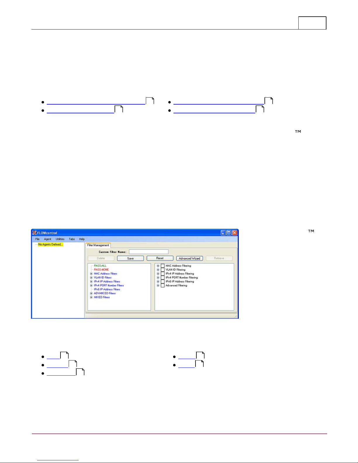
7.2.2 Filter Management
FLOWcontrol™ provides the capability to manage filters off-line. Upon starting
FLOWcontrol™, not only does the Agent List appear, but a tab control appears
in the left hand pane of the FLOWcontrol™ Main Screen. From the "Filter
Management" tab, filters can be added, deleted or modified. An Advanced
Wizard is provided to ease filter creation. The Advanced Wizard provides a
methodology for creation of complex filters. Each of the filters created, both with
and without the wizard, are grouped into the following major sections.
MAC Address Filters
VLAN ID Filters
IPv4 IP Address Filters
IPv4 PORT Number Filters
IPv6 IP Address Filters
ADVANCED Filters
MIXED Filters
Frame Type and Protocol Filters built in the Advanced Wizard are considered
ADVANCED Filters and will appear under this major section.
The Filter Management capability provides the user with off-line filter
management. Filters can be created, deleted, and modified without being
attached to a specific filtered product. In addition, a wizard is provided to
facilitate easy filter creation. The Filter Management screen is depicted next.
Filter Management is divided into two major areas, the first is Saved Filters (left
hand panel), which sorts the saved filters into major groups and the second is
Filter Specifics (right hand panel) which is used to define a filter with various
parts. The button is used to delete a currently defined filter. This is
done by selecting a filter which is a subordinate node in the Saved Filters panel.
VERSA™stream
© 2010 Datacom Systems Inc
Page 37

FLOWcontrol™
The Saved Filters Panel consists of a tree view
that has a total of nine groupings as depicted.
PASS-ALL and PASS-NONE are fixed entries. The
next seven groupings contain filters that are
specific to a given filter type. The last grouping
(MIXED Filters) contains filters that are made up of
multiple elements of any of the previous six
groupings. The six individual groupings are:
MAC Address Filters
VLAN ID Filters
IPv4 IP Address Filters
IPv4 PORT Number Filters
IPv6 IP Address Filters
ADVANCED Filters
Expanding a Filter type will give a list of filters within that group. Doubleclicking on a filter will populate the Filter Specifics panel with the filter
definition. No changes can be made to a given filter within this area of the Filter
Management control. Changes are made in the Filter Specifics panel.
37
The top level nodes of the Saved Filters panel cannot be deleted. A confirmation
for deletion of a filter is required. Once a filter definition has been specified in
the Filter Specifics panel, the filter can be saved using the button. In
order for the save to be completed, a filter name must be entered. If a filter
already exists by that name, a confirmation dialog box is presented asking if the
current filter definition is to be overwritten. The button is used to
clear out any current definitions in the Filter Specifics panel so that a new filter
definition can be created. The button presents a wizard to the user
that allows a guided approach to filter creation. More information on this wizard
is found elsewhere in this document. The button allows for retrieval of
a filter definition currently assigned to a given port filter. The is only
enabled when attached to a Filtered product.
Since FLOWcontrol™ supports multiple connections to Filtered products,
selection of the button presents a list of connected filter products
from which to choose. If only one connected Filtered product is populated, a list
will not be shown. Selection of a filtered product from the dialog box combo box
then determines the number and names of the ports on the filtered product and
presents another dialog box with the list of ports from which to select. Selection
of a port from this list then proceeds to another dialog box asking which filter to
retrieve. Depending upon the product, the list of filters available may vary.
Specifically for the Filtered SINGLEstream™, only an Ingress and Egress filter
will be available for retrieval. For the Filtered VERSAstream, multiple ingress and
a single egress filter may be retrieved.
7.2.2.1 Saved Filters Panel
© 2010 Datacom Systems Inc
VERSA™stream
Page 38

FLOWcontrol™38
The Filter Specifics Panel consists of a tree view
that has a total of six groupings as depicted.
MAC Address Filtering
VLAN ID Filtering
IPv4 IP Address
Filtering
IPv4 PORT Number Filtering
IPv6 IP Address Filtering
Advanced Filtering
7.2.2.2 Filter Specifics Panel
The six individual filter groupings consist of a unique blend of elements with
specific differences based upon the filter type. The individual group definitions
are represented in the following six figures:
VERSA™stream
© 2010 Datacom Systems Inc
Page 39

FLOWcontrol™
A filter can consist of multiple filter types. For
example, a filter can be created which is looking
for a source MAC Address of 00-14-E2-00-F9-34
and a VLAN Tag range of 10-25. This filter
definition is represented in the following Filter
Specifics Panel. With a filter of multiple filter
types, the saved filter will appear in the MIXED
filters tree. Otherwise, the specific Filter type
will be populated in the saved filter tree.
7.2.2.2.1 Include/Exclude Definition
39
Within a Filter Type, the filter can be defined as either an Include or an Exclude
Filter. These are mutually exclusive. Each Filter Type has a unique Include/
Exclude flag. For instance, the MAC Address Filter definition may be an Include
Filter, while a VLAN ID Filter may be an Exclude Filter. The Include Filter and
Exclude Filter check boxes apply to all of the Filter Types.
7.2.2.2.2 Include VLAN Tunneling Frames
The Include VLAN Tunneling Frames check box is found in the following Filter
Types:
VLAN ID Filter
IPv4 Address Filter
IPv4 PORT Filter
IPv6 Address Filter
This flag, if checked, forces the filter engine to examine an Ethernet frame to
determine if the frame is a VLAN tagged frame. If so, the specified filter will
accommodate an offset to correspondingly examine the packet structure for a
match whether the frame is VLAN tagged or not.
For example, if a filter is defined to match an IPv4 Source Address of
12.45.76.98, the filter engine examines the frame to determine if the source
address found at offsets 26,27,28,29 (zero based) are equal to 12,45,76,98. In
addition, if the VLAN Tunneling Frames checkbox is checked, the filter engine
will also check offsets 12,13,30,31,32,33 (zero based) for values equal to
81,00,12,45,76,98. If an incoming frame matches either of these definitions, the
frame will be passed by the filter engine.
© 2010 Datacom Systems Inc
VERSA™stream
Page 40

FLOWcontrol™40
7.2.2.2.3 Rule Definition
A Rule Definition can vary between Filter Types. The Filter Engine allows for a
total of 16 rules for each of:
MAC Address Filter
VLAN ID Filter
IPv4 Address Filter
IPv4 PORT Number Filter
IPv6 Address Filter
In this context, the following applies:
Range Definitions: If any range of values is defined, the number of rules that
are able to be managed by the user drops from 16 to 8. The reason for this is
that a range consumes two rules. If Rule 1 is defined as a Destination Address
value and Rule 2 is a range of Source Addresses, a total of 4 rules are
consumed. This is handled within the Filter Engine as Rule 1 equals a
Destination Address range with the lower and upper values of the range equal to
one another. If there are no ranges defined, then a total of 16 rules are still
available.
Directional Selections: are applicable for the following Filter Types only:
MAC Address Filter
IPv4 Address Filter
IPv4 PORT Number Filter
IPv6 Address Filter
The Directional Selections include:
Source --> Destination
Destination --> Source
Bidirectional <-> Directional Selection
For the Directional Selections of Source --> Destination and Destination -->
Source, no special rule handling is required other than that already specified for
Range Definitions. However, for the Bidirectional <-> Directional Selection, The
Source and Destination Addresses are added as two different rules, one with the
Source and Destination Addresses as specified and a second rule with the Source
and Destination Addresses reversed (i.e., Source Address set for the specified
Destination Address and the Destination Address set for the specified Source
Address). Consequently, the number of rules is reduced by a factor of 2.
Therefore, if only Source and/or Destination addresses are specified in a filter
definition, 16 rules are available. If the Bidirectional <-> selection is made, the
number of rules avaliable to the user is reduced to 8. In addition if a range is
specified, the number of rules available to the user reduces to 4.
VERSA™stream
© 2010 Datacom Systems Inc
Page 41

FLOWcontrol™
Source/
Destination
Address Only
Source/
Destination
Ranges
Source/
Destination
Bidirectional
Source/
Destination
Ranges,
Bidirectional
Maximum Rules
MAC Address
Filter
16 Rules
Allowed
8 Rules Allowed
8 Rules Allowed
4 Rules Allowed
16 Rules
Allowed
VLAN ID Filter
16 Rules
Allowed
8 Rules Allowed
Not Applicable
Not Applicable
16 Rules
Allowed
IPv4 IP
Address Filter
16 Rules
Allowed
8 Rules Allowed
8 Rules Allowed
4 Rules Allowed
16 Rules
Allowed
IPv4 PORT
Number Filter
16 Rules
Allowed
8 Rules Allowed
8 Rules Allowed
4 Rules Allowed
16 Rules
Allowed
IPv6 IP
Address Filter
16 Rules
Allowed
8 Rules Allowed
8 Rules Allowed
4 Rules Allowed
16 Rules
Allowed
Advanced Filter
Not Applicable
Not Applicable
Not Applicable
Not Applicable
2 Rules Allowed
41
Advanced Filter: The maximum number of rules available for an Advanced Filter
is 2. Each of these rules consist of up to 64 offset values, where a binary mask,
comparison equation, and value are defined. Specifics are given later. The
following table applies for each of the Filter Type Definitions.
7.2.2.2.4 Combinatorial Logic
The combinatorial logic that is applied for all the filters is as follows. Each Filter
Type is ANDed with every other Filter Type to determine if a match is made. In
addition, within a Filter Type, individual rules are ORed together. For Advanced
Filters, the specific offset values specified are ANDed together. A mixed filter
consisting of MAC Addresses, VLAN IDs and Advanced Filters is expressed in the
following figures. The logic of the filter follows the four filter panel figures:
© 2010 Datacom Systems Inc
VERSA™stream
Page 42

FLOWcontrol™42
This filter is examining an incoming frame to see if:
{Source MAC Address is EQUAL 00-14-E2-00-00-1F
OR
Destination MAC Address is EQUAL 00-14-E2-00-00-1F
OR
(Source MAC Address is between 22-EF-45-00-00-00 AND 22-EF-45-FF-FF-FF)
AND
(Destination MAC Address is between 22-EF-45-00-00-00 AND 22-EF-45-FF-FFFF)}
AND
{VLAN ID is between 2 AND 10
OR
VLAN ID is EQUAL 100}
AND
{Offset 14, bits 6,7,8 = 0x60, which corresponds to a VLAN Priority of 3
OR
Offset 14, bits 6,7,8 = 0xE0, which corresponds to VLAN Priority of 7}
VERSA™stream
© 2010 Datacom Systems Inc
Page 43

FLOWcontrol™
43
Understanding these basic rules allows you to create more complicated
filters:
[[VLAN1] OR [VLAN2]] AND [[IP Address1] OR [IP Address2]] AND
[[Port1] OR [Port2]]
For example:
VLAN ID AND [[Dest. IP Range 1] OR [Dest. IP Range 2] AND Dest. Port
Range
VLAN ID=5 AND [[10.1.1.0-10.1.1.255] OR 10.2.2.0 -10.2.2.255] AND Ports
16384-32767
The Advanced Filter rules are combined according to the OR function. There
are 2 Advanced filters available. Traffic must comply with one rule in order
for the filter to be applied.
[Rule 1] OR [Rule 2]
Advanced Filter offsets are combined according to the AND function. Traffic
must comply with all applied offsets for the filter to be applied. Offsets that
are blank have no effect on filtering.
[Offset 1] AND [Offset 2] AND [Offset 3] AND [Offset 4]
© 2010 Datacom Systems Inc
VERSA™stream
Page 44

FLOWcontrol™44
7.2.2.2.5 MAC Address Filter
The MAC Address Filter defines an exact Source Address, Destination Address, or
Source/Destination Address pair. Ranges of each of these can be specified and a
directional indicator specified. The directional indicator "Source --> Destination"
will place the specified Source and Destination Address value(s)/range(s) in the
applicable Filter Engine comparison tables. The directional indicator "Destination
--> Source" will place the specified Source and Destination Address value(s)/
range(s) in the Filter Engine comparison tables with opposite orientation. The
specified Source Address value(range) will be placed in the Destination table
location(s) and the Destination Address value(range) will be placed in the
Source table location(s). The directional indicator "Bidirectional <->" will place
one entry with the Source and Destination Address value(s)/range(s) into the
applicable locations in the Filter Engine comparison tables and a second entry
with the Source and Destination Address value(s)/range(s) in the opposite
locations.
The MAC Address format is written in hexadecimal with hyphen (-) separators.
For example, a valid MAC Address is 00-34-F5-E2-14-0C. The MAC Address Filter
is bound by the Rule Definition limitations.
7.2.2.2.6 VLAN ID Filter
40
The VLAN ID Filter definition is used to specify an exact VLAN ID or a range of
VLAN IDs. The VLAN ID is located in two bytes, specifically offsets 14/15 where
the lower four bits of offset 14 and the entire byte of offset 15 are used for the
VLAN ID. This corresponds to 12 bits of data, which corresponds to a maximum
VLAN ID of 4095. Consequently, the maximum value that can be specified in the
definition of a VLAN ID filter is 4095. The VLAN IDs are specified as integers.
The VLAN ID Filter is bound by the Rule Definition limitations.
7.2.2.2.7 IPv4 IP Address Filter
40
The IPv4 IP Address Filter definition is used to specify an exact Source Address,
Destination Address, or a Source/Destination Address pair. In addition, ranges of
each of these can be specified and a directional indicator specified. The
directional indicator "Source --> Destination" will place the specified Source and
Destination Address value(s)/range(s) in the applicable Filter Engine comparison
tables. The directional indicator "Destination --> Source" will place the specified
Source and Destination Address value(s)/range(s) in the Filter Engine
comparison tables with opposite orientation. In other words, the specified
Source Address value(range) will be placed in the Destination table location(s)
and the Destination Address value(range) will be placed in the Source table
location(s). The directional indicator "Bidirectional <->" will place one entry with
the Source and Destination Address value(s)/range(s) into the applicable
locations in the Filter Engine comparison tables and a second entry with the
Source and Destination Address value(s)/range(s) in the opposite locations.
The IPv4 IP Address format is written as integers between 0 and 255 with period
(.) separators. For example, a valid IPv4 IP address is 13.45.234.100. The IPv4
IP Address Filter is bound by the Rule Definition limitations.
VERSA™stream
40
© 2010 Datacom Systems Inc
Page 45

FLOWcontrol™
7.2.2.2.8 IPv4 PORT Number Filter
45
The IPv4 PORT Number Filter definition is used to specify an exact Source Port
Number, Destination Port Number, or Source/Destination Port Number pair. In
addition, ranges of each of these can be specified and a directional indicator
specified. The directional indicator "Source --> Destination" will place the
specified Source and Destination Port Number value(s)/range(s) in the applicable
Filter Engine comparison tables. The directional indicator "Destination -->
Source" will place the specified Source and Destination Port Number value(s)/
range(s) in the Filter Engine comparison tables with opposite orientation. In
other words, the specified Source Port Number value(range) will be placed in the
Destination table location(s) and the Destination Port Number value(range) will
be placed in the Source table location(s). The directional indicator "Bidirectional
<->" will place one entry with the Source and Destination Port Number value(s)/
range(s) into the applicable locations in the Filter Engine comparison tables and
a second entry with the Source and Destination Port Number value(s)/range(s) in
the opposite locations.
The IPv4 PORT Number format is written as integers between 0 and 65,535 with
period (.) separators. For example, a valid IPv4 PORT Number is 2370. The IPv4
PORT Number Filter is bound by the Rule Definition limitations.
40
7.2.2.2.9 IPv6 IP Address Filter
The IPv6 IP Address Filter definition is used to specify an exact Source Address,
Destination Address, or Source/Destination Address pair. In addition, ranges of
each of these can be specified and a directional indicator specified. The
directional indicator "Source --> Destination" will place the specified Source and
Destination Address value(s)/range(s) in the applicable Filter Engine comparison
tables. The directional indicator "Destination --> Source" will place the specified
Source and Destination Address value(s)/range(s) in the Filter Engine
comparison tables with opposite orientation. In other words, the specified
Source Address value(range) will be placed in the Destination table location(s)
and the Destination Address value(range) will be placed in the Source table
location(s). The directional indicator "Bidirectional <->" will place one entry with
the Source and Destination Address value(s)/range(s) into the applicable
locations in the Filter Engine comparison tables and a second entry with the
Source and Destination Address value(s)/range(s) in the opposite locations.
The IPv6 IP Address is typically composed of two logical parts: a 64-bit (sub-)
network prefix and a 64-bit host part. IPv6 address format is written in
hexadecimal notation with colon (:) separators. For example, a valid IPv6 IP
address is 2009:ec7:74b3::7b1e:481:6225. The IPv6 IP Address Filter is bound
by the Rule Definition limitations.
40
© 2010 Datacom Systems Inc
VERSA™stream
Page 46

FLOWcontrol™46
Equals
Not Equals
Greater Than
Less Than
Greater Than or Equals
Less Than or Equals
As an example of an Advanced Filter, if bit 5 is to be evaluated, the mask
should be set to "00010000", the equation set to Equals and the value set to
the hex value of the mask, in this case 0x10. In the case of evaluation of
multiple bits, the mask should have a "1" set for each of the bits to be
evaluated and "0" for all other bits. The
comparison value should be specified as
appropriate for the comparison and the value
should correspond to the value for which a
pass condition would be desired. As an
example, evaluation of bits 2,3,4 for a value
greater than 2 would be specified as a mask of
"00001110", a comparison value of GREATER
THAN and a value of 0x04, which corresponds
to a bit value of "00000100" with the bolded
characters corresponding to the value of 2 for
the selected bits.
The figure to the right shows a filter designed
to pass any frame seen with a destination
MAC address vendor ID equal to 00-14-E2,
which is the Vendor ID for Datacom Systems
Inc.
7.2.2.2.10 Advanced Filter
The Advanced Filter allows for considerable flexibility in selection of a specific
value at a given offset within a frame. As a result, each of the two rules
available provide the flexibility to specify values for each of the first 64 bytes of
a received frame. Some examples of Advanced filters include:
IPX Frames (offsets 12/13 = 0x81/0x37)
IPv4 Frames (offsets 12/13 = 0x08/0x00)
TCP Frames (offsets 12/13/23 = 0x08/0x00/0x06)
Each frame offset has a bit mask, a comparison equation, and a value.
The binary mask is used to specify a specific(set) of bit(s) that will mask a given
byte of a frame to allow specific comparisons on the selected bits. This is useful
when looking for frames such as TCP Reset frames. Normally, if a specific bit is
to be evaluated, the mask needs to specify which bit is to be compared with a
"1" and all other mask bits equal to "0".
The possible comparison equations are as follows:
The values are specified in two digit hex notation (0x??), which corresponds to a
value that can be specified in a single byte of data.
VERSA™stream
© 2010 Datacom Systems Inc
Page 47

FLOWcontrol™
7.2.2.2.11 Context Menus
47
Context menus are only available when dealing with the Rule Sets of a filter in
the Filter Specifics panel.
The Add option is available on any of the Rule Sets or Rule # tree values.
The Delete option is available only on Rule # nodes greater than 1 for:
MAC Address Filter
VLAN ID Filter
IPv4 IP Address Filter
IPv4 PORT Number Filter
IPv6 IP Address Filter
Neither the Add or Delete Context Menu options are available in the Advanced
Filter type as the number of Rules in this filter type are fixed.
7.2.2.2.12 Value Specifications
Value Specifications within the Filter Specifics Panel of FLOWcontrol™ are
changed in various fashions, depending on the items.
The checkbox nodes of:
Include Filter
Exclude Filter
Include VLAN Tunneling Frames
are changed by double-clicking on the node in the tree. In the case of the
Include Filter or the Exclude Filter, double-clicking will check the selected node
and uncheck the other as the Include and Exclude Filters are mutually exclusive.
In the case of the Include VLAN Tunneling Frames node, double-clicking on the
node will toggle between the checked and unchecked state.
The Rule Set and Rule # nodes are toggled from an expanded to a collapsed
state when a double-click of that node is performed. In addition, the same
functionality can be performed by clicking on the Å node.
Double-clicking on a Range node will toggle from an expanded to a collapsed
state showing/hiding the range values for a selected range node.
Double-clicking on a value will present a dialog box requesting a value to be
specified. In the case of double-clicking on either the upper or lower value of a
range, the lower value dialog box will be displayed. Upon accepting or clicking
the button, the upper range value dialog box will be presented. Upon
accepting or clicking the button, the values in the Filter Specifics Panel
will be updated with the entered values. If the button is depressed in
either of the upper or lower range, the values will be cleared. In addition if the
value is cleared in either of the dialog boxes, both the upper and lower values
will also be cleared.
© 2010 Datacom Systems Inc
VERSA™stream
Page 48

7.2.2.3 Advanced Filter Wizard
The Advanced Filter
Wizard provides a
guided approach to
creation of filters for
application to filtered
products. This wizard
facilitates creation of a complex filter using easy to follow screens. The
wizard is started by selecting the button. The initial screen
beginning the filter creation is presented to have the user ensure that a filter
is in fact desired to be created.
Upon selection of the button, the MAC Address entry screen is
presented. Selection of the cancels the wizard completely. Any
information entered will be lost.
In order to enable MAC Address
filtering, select
so data entry of MAC Address
Filtering Configuration grouping
will be enabled and can now be
completed as described in the
MAC Address Wizard section of
this document. When completed,
selection of the button will
proceed to the VLAN ID Filtering
entry screen. If the filter
specification has been completed,
click on the button.
In order to enable VLAN ID
filtering, must be
selected so the VLAN ID Filtering
Configuration grouping will be
enabled. Data entry of VLAN ID
filtering parameters can now be
completed as described in the VLAN
ID Wizard section of this
document. When completed,
selection of the button will
proceed to the VLAN ID Filtering
entry screen. If further configuration
of MAC Address filtering is desired,
click on the button. If the
filter specification has been
completed, click on the
button.
FLOWcontrol™48
51
VERSA™stream
53
© 2010 Datacom Systems Inc
Page 49

FLOWcontrol™
In order to enable ETHERtype
filtering,
must be selected so, the
ETHERtype Filtering
Configuration grouping will be
enabled. Selection of the
ETHERtype filtering options
can now be completed as
described in the ETHERtype
Wizard section of this
document. When completed,
selection of the button
will proceed to the IPv4 IP
Address Filtering entry
screen. If further
configuration of VLAN ID
filtering is desired, click
on the button. If the filter specification has been completed, click on
the button.
In order to enable IPv4 IP Address
filtering, must be
selected so the IPv4 IP Address
Filtering Configuration grouping will
be enabled. Selection of the IPv4 IP
Address filtering parameters can
now be completed as described in
the IPv4 IP Address Wizard
section of this document. When
completed, selection of the
button will proceed to one of either
the IPv4 Protocol Filtering entry
screen or the IPv4 Port Number
entry screen, depending on whether
or not ETHERtype filtering has been
enabled or not. If further
configuration of filtering that has already been enabled/configured is desired,
click on the button. If the filter specification has been completed, click
on the button.
49
54
55
© 2010 Datacom Systems Inc
VERSA™stream
Page 50

FLOWcontrol™50
In order to enable IPv4 Protocol
Filtering, must be
selected so the IPv4 Protocol
Filtering Configuration grouping will
be enabled. The IPv4 Protocol can
be selected from the combo box
with the known IPv4 protocols
making up the list. When
completed, selection of the
button will proceed to the IPv4 Port
Number entry screen. If further
configuration of filtering that has
already been enabled/configured is
desired, click on the button.
If the filter specification has been
completed, click on the
button.
In order to enable IPv4 PORT
Number filtering,
must be
selected so, the IPv4 IP PORT
Number Filtering Configuration
grouping will be enabled. Selection
of the IPv4 PORT Number filtering
parameters can now be completed
as described in the IPv4 PORT
Number Wizard section of this
document. If further configuration
of filtering that has already been
enabled/configured is desired,
click on the button. If the
filter specification has been
completed, click on the
button.
57
VERSA™stream
© 2010 Datacom Systems Inc
Page 51

FLOWcontrol™
The button is used to add table
entries from scratch.
The button is used to
remove entire table rows. This button
is only enabled when an entire row
has been highlighted.
The button is used to copy a
selected table and add the row to the
end of the currently entered table.
The row type only is copied. Specific
data is required to be entered for a complete specification of a given filter row.
The button is used to cancel ALL entered filter specifications and return to
the Filter Management Screen. The button always takes all currently
entered data and populates the information in the Filter Specifics Panel with the
selected data entered in the applicable area on the screen.
The MAC Address filter being created is either an Include or an Exclude filter as
determined by selecting the or the radio button. The two are
mutually exclusive. Selection of the Include Filter disables the Exclude Filter and
vice-versa. Individual MAC Address filter entries can now be made. When all
data entry is complete for the MAC Address Filter, click the button.
To add entries to the MAC Address filter
table, select the button, which
adds a row to the table with the values
specified as depicted.
A valid MAC Address entered in the
second column will enable the Rule
automatically.
7.2.2.3.1 MAC Address Wizard
51
The MAC Address Wizard enables the creation of a table of MAC Address
comparisons to be made against each incoming frame. Said entries can be made
using the procedures outlined below. The three buttons available within the MAC
Address Filtering Configuration are:
© 2010 Datacom Systems Inc
VERSA™stream
Page 52

FLOWcontrol™52
If the MAC Address table
entry is supposed to be a
Source Range, enter data
as depicted.
If the MAC Address is supposed to be
a Destination Address, modify the
Direction combo box as indicated and
enter a valid MAC Address.
If the MAC Address
entry is to be a
Destination Range,
enter data as depicted.
If the MAC Address entry is to be a specific Source/Destination Address pair,
enter data as depicted below
Either the Source or Destination Ranges can be specified with appropriate
screens as given below.
Please note that the upper Destination Address is auto-filled to the lower
Destination MAC Address value. As noted in the Rule Definitions section of
this document, ANY range definitions require ALL table entries to be treated as
ranges.
VERSA™stream
40
© 2010 Datacom Systems Inc
Page 53

FLOWcontrol™
The button is used to add table
entries from scratch.
The button is used to
remove entire table rows. This button
is enabled when an entire row has
been highlighted.
The button is used to copy a
selected table and add the row to the
end of the currently entered table.
The row type only is copied. Specific data is required to be entered for a
complete specification of a given filter row.
The button is used to cancel ALL entered filter specifications and return to
the Filter Management Screen. The button always takes all currently
entered data and populates the information in the Filter Specifics Panel with the
selected data entered in the appropriate area on the screen.
The VLAN ID filter being created is either an Include or an Exclude filter as
determined by selecting the or the radio button. The two are
mutually exclusive. Selection of the Include Filter disables the Exclude Filter and
vice-versa. Individual VLAN ID filter entries can now be made. When all data
entry is complete for the VLAN ID Filter, click the button.
To add entries to the VLAN ID filter table, select
the button, which adds a row to the table
with the values specified as depicted.
A valid VLAN ID (0-4095) entered in the second
column will enable the Rule automatically.
7.2.2.3.2 VLAN ID Wizard
53
The VLAN ID Wizard enables the creation of a table of VLAN ID comparisons to
be made against each incoming frame. Said entries can be made using the
procedures outlined below. The three buttons available within the VLAN ID
Filtering Configuration are:
© 2010 Datacom Systems Inc
VERSA™stream
Page 54

FLOWcontrol™54
If the VLAN ID table entry is supposed to
be a Range, enter data as depicted.
The ETHERtype Wizard
enables filtering on a
specific ETHERtype. Only
a single entry can be
examined within a given
filter as this filter type
makes use of the
Advanced Filtering
capability, which
consists of only 2 rules.
The first rule is used for
evaluation of a
particular frame for a
specified ETHERtype.
The second rule is
reserved in case
evaluation of a VLAN
tagged frame is
required. Therefore, this
wizard only allows for
the selection of a single ETHERtype as ETHERtype 8848 (MPLS) is selected in
the screen below. The list of ETHERtypes is found in the installed directory for
FLOWcontrol™ in a text file called Ethertypes_FC.txt.
As noted in the Rule Definitions section of this document, ANY range
40
definitions require ALL table entries to be treated as ranges.
7.2.2.3.3 ETHERtype Wizard
The button is used to cancel ALL entered filter specifications and return to
the Filter Management Screen. The button takes all currently entered
data and populates the information in the Filter Specifics Panel with the
selected data entered in the applicable area on the screen.
NOTE: If this filter is enabled, the IPv4 Protocol Filter will not be available.
VERSA™stream
© 2010 Datacom Systems Inc
Page 55

FLOWcontrol™
The button is used to add table
entries from scratch.
The button is used to
remove entire table rows. This button
is only enabled when an entire row has
been highlighted.
The button is used to copy a
selected table and add the row to the
end of the currently entered table. The row type only is copied. Specific data is
required to be entered for a complete specification of a given filter row.
The button is used to cancel ALL entered filter specifications and return to
the Filter Management Screen. The button takes all currently entered
data and populates the information in the Filter Specifics Panel with the
selected data entered in the applicable area on the screen.
The IPv4 IP Address filter being created is either an Include or an Exclude filter
as determined by selecting the or the radio button. The two are
mutually exclusive. Selection of the Include Filter disables the Exclude Filter and
vice-versa. Individual IPv4 IP Address filter entries can now be made and when
all data entry is complete for the IPv4 IP Address Filter, click the button.
To add entries to the IPv4 IP Address
filter table, select the button,
which adds a row to the table with the
values specified as depicted.
A valid IPv4 IP Address entered in the
second column will enable the Rule
automatically.
If the IPv4 IP Address table
entry is supposed to be a
Source Range, enter data as
depicted.
7.2.2.3.4 IPv4 IP Address Wizard
55
The IPv4 IP Address Wizard enables the creation of a table of IPv4 IP Address
comparisons to be made against each incoming frame. Said entries can be made
using the procedures outlined below. The three buttons available within the IPv4
IP Address Filtering Configuration are:
© 2010 Datacom Systems Inc
VERSA™stream
Page 56

FLOWcontrol™56
If the IPv4 IP Address is supposed
to be a Destination Address, modify
the Direction combo box as
indicated and enter a valid IPv4 IP
Address.
If the IPv4 IP Address
entry is to be a
Destination Range,
enter data as depicted.
The IPv4 Protocol Wizard enables
filtering on a specific Protocol. Only a
single entry can be examined within
a given filter as this filter type
makes use of the Advanced Filtering
capability, which consists of only 2
rules. The first rule is used for
evaluation of a particular frame for a
specified Protocol. The second rule is
reserved in case evaluation of a
VLAN tagged frame is required. Thus,
this wizard only allows for the
selection of a single Protocol # 92
MTP (Multicast Transport Protocol)
as shown in the screen. The list of IPv4 Protocols is found in the installed
directory for FLOWcontrol™ in a text file called IPv4Protocol.txt.
If the IPv4 IP Address entry is to be a specific Source/Destination Address pair,
enter data as depicted below.
Either the Source or Destination Ranges can be specified with appropriate
screens as given below.
As noted in the Rule Definitions section of this document, ANY range
40
definitions require ALL table entries to be treated as ranges.
7.2.2.3.5 IPv4 Protocol Wizard
VERSA™stream
© 2010 Datacom Systems Inc
Page 57

FLOWcontrol™
The button is used to add table
entries from scratch.
The button is used to remove
entire table rows. This button is only
enabled when an entire row has been
highlighted.
The button is used to copy a
selected table and add the row to the
end of the currently entered table. The row type only is copied. Specific data
will still be required to be entered for a complete specification of a given filter
row.
The button is used to cancel ALL entered filter specifications and return to
the Filter Management Screen. The button takes all currently entered
data and populates the information in the Filter Specifics Panel with the
selected data entered in the applicable area on the screen.
The IPv4 PORT Number filter is created by selecting either the or the
radio button. The two are mutually exclusive. Selection of the Include
Filter disables the Exclude Filter and vice-versa. Individual IPv4 PORT Number
filter entries can now be made. When all data entry is complete for the IPv4
PORT Number Filter, click the button.
To add entries to the IPv4 PORT
Number filter table, select the
button, which adds a row to the table
with the values specified as depicted.
57
The button is used to cancel ALL entered filter specifications and return to
the Filter Management Screen. The button takes all currently entered
data and populates the information in the Filter Specifics Panel with the
selected data entered in the applicable area on the screen.
NOTE: This filter will only be available if the ETHERtype filter has not already
been enabled.
7.2.2.3.6 IPv4 PORT Number Wizard
The IPv4 PORT Number Wizard enables the creation of a table of IPv4 PORT
Number comparisons to be made against each incoming frame. Said entries can
be made using the procedures outlined below. The three buttons available
within the IPv4 PORT Number Filtering Configuration are:
© 2010 Datacom Systems Inc
VERSA™stream
Page 58

FLOWcontrol™58
A valid IPv4 PORT Number entered in
the second column will enable the
Rule automatically.
If the IPv4 PORT Number
table entry is supposed to
be a Source Range, enter
data as depicted.
If the IPv4 PORT Number is
supposed to be a Destination
Address, modify the Direction
combo box as indicated and enter a
valid IPv4 PORT Number.
If the IPv4 PORT
Number entry is to be a
Destination Range,
enter data as depicted.
If the IPv4 PORT Number entry is to be a specific Source/Destination Address
pair, enter data as depicted below.
Either the Source or Destination Ranges can be specified with appropriate
screens as given below.
Please note that the upper Destination Address is auto-filled to the lower
Destination IPv4 PORT Number value. As noted in the Rule Definitions section
40
of this document, ANY range definitions require ALL table entries to be treated
as ranges.
VERSA™stream
© 2010 Datacom Systems Inc
Page 59

FLOWcontrol™
The FLOWcontrol™ Communications
Console available is a terminal
emulationapplication that provides
connectivity between FLOWcontrol
and a selected agent using either
Telnet or Serial communications. The
Communications Console main screen
is depicted.
The File pull-down menu provides several options:
Send Text File
Create FVS-1080 Upgrade Scripts
Capture
Clear
The Communication pull down menu provides a means to
Connect or Disconnect from a given communications
device. These menu options provide the same functionality
as the button.
7.2.3 Communications Console
Within the Communications Console, there are two pull down menu items:
File
Communication
7.2.3.1 Pull Down Menus
59
Send Text File is used to transmit a text file to a connected device. This is
helpful for a variety of purposes. Primarily in the functionality of the Telnet/
Serial client, sending a script file containing a series of commands appropriate
for performing upgrades is applicable.
Create FVS-1080 Upgrade Scripts creates upgrade scripts based upon an
entered tftp or ftp server and a designated directory into which to place the
files. If used in conjunction with a tftp server, the files should be located in the
tftp server designated directory.
Capture provides a means of capturing text into a file for later use. The Capture
menu option provides the ability to start and stop the capture process. In
addition, a location may be selected into which the file is to be stored.
Clear removes all text from the console window.
© 2010 Datacom Systems Inc
VERSA™stream
Page 60

FLOWcontrol™60
From the Communications Console
main screen, a communications type
can be selected, either Telnet or serial
. Serial is used primarily for initial
setup, utilizing a specific COM port or
for diagnostics, if the management port
is not responding.
initiates a ping every
second for a selected IP Address,
reports the ping status and is
available only when Telnet
connectivity is selected. When
selected becomes
and the becomes disabled.
Selection of terminates the
ongoing pings, becomes and is enabled.
The Product Control Screen varies
from product to product (see the
Supported Products section) and
each product contains specific tabs
unique to that product. A graphic
representation of the front panel
of the product to which connection
has been made is displayed. For
example, the following is a
snapshot of the
Product Control Screen for the VS-1214-10G.
7.2.3.2 Console Main Screen
Selection of , enables and displays a text field where a valid IPv4 IP
address can be entered.
Selection of a serial port as in , enables and displays a combo box
containing possible baud rate options .
Only baud rates for Datacom Systems products are provided:
opens either the Telnet or Serial port selected connection.
becomes upon successful connection. A broken connection can result for
various reasons and when the Communications Console becomes aware of a
broken connection or the, the interrupts the Telnet or Serial connection
the becomes .
7.2.4 Product Control
25
The individual tabs will be described on a product by product basis in the
following sections.
VERSA™stream
© 2010 Datacom Systems Inc
Page 61

FLOWcontrol™
Tab
Description
Configuration Summary
This tab interrogates the connected product and
ascertains information regarding the current
configuration for Port Names, Port Speeds (both
configured and current), Port Media (Fiber or
Copper), Port Assignments (Network or Monitor),
Aggregation Settings, and Filter Settings
Port Configuration
This tab allows both readback and set capabilities
of:
Port Names (Maximum of 16 characters)
Port Speeds (10/100/1000 Mbits/sec)
Port Media (Fiber or Copper)
Port Assignment (Network or Monitor)
Depending on the product type, some values may
not be adjustable.
Aggregation Configuration
— Colors: —
Red:
Pass None
Green:
Pass All
Blue:
Filter Applied
Purple:
Rule Change until
readback shifts to
red, green or blue.
This tab allows both readback and set capabilities.
The tree view presented may correspond to ingress
or egress focused operation. In the case of ingress
focused orientation, the top level node received
data is copied/routed to each of the selected
subordinate nodes. In the case of egress focused
orientation, each of the selected subordinate nodes
received data is copied/routed to the top level
node.
Filter Configuration
This tab allows for configuration of filters for either
the FSS or FVS product lines. Depending upon the
model, different filters will become available for
configuration.
Event Log
This tab is used for read only status of the events
seen by the product. The Event Log can be reset
from this element, but no specific events may be
written through this module.
7.2.4.1 Product Control Tabs
A basic description of Product Control tabs:
61
7.2.4.1.1 Configuration Summary
The Configuration Summary tab provides a view into the connected product.
Clicking updates the displayed information. allows for the
selective resetting of various counters within the Filter Engine.
By expanding the Configuration Summary treeview, the user can review the
properties of Network and/or Monitor ports.
© 2010 Datacom Systems Inc
VERSA™stream
Page 62

FLOWcontrol™62
Individual counters within the FVS-1080
can be reset, other products do not
currently support this function. To initiate
a counter reset, click within the
Product Control Screen Configuration
Summary tab. Three options are available,
pressing will abort any counter
resets from being performed.
Upon selection of , then a dialog
box will appear asking for selection of an
Egress Port for which the reset function
should be performed.
The selections available are:
ALL EGRESS PORTS
Each port name noted as Local Name (Port Name)
Selection of any of the items on the
available list and clicking , a new
dialog box requesting the counters to be
reset will appear.
7.2.4.1.1.1 Filtered SINGLEstream Summary
The Filtered SINGLEstream™ (FSS; 10G) models identified in the Supported
Products section have a fixed number of Network and Monitor Ports. The
25
Network Ports are actually Network TAP ports.
Network TAP Ports are not available for monitoring traffic - each port is a part
of a Network Tap. Network Taps consist of A and B ports.
Monitor Ports are used to provide network data to connected analysis devices.
7.2.4.1.1.2 Filtered VERSAstream Summary
The Filtered VERSAstream™ (FVS-1044BT; FASTAP-1044BT; 10G) models
identified in the Supported Products section have a fixed number of Network
25
and Monitor Ports.
Network Ports on the Filtered VERSAstream™ receive SPAN port traffic, Port
Mirrors, or the monitor side of a stand-alone network tap. Data received via the
Network Input Port is copied, filtered, and then replicated on the identified
Monitor Ports.
Monitor Ports are used to provide network data to connected analysis devices.
7.2.4.1.2 Counter Resets
VERSA™stream
© 2010 Datacom Systems Inc
Page 63

FLOWcontrol™
The selections available are:
If ALL STATISTICS or Interim Counters are
selected and is selected, a new
dialog box requesting the Ingress port
counters to be reset is presented.
The selections available are:
ALL EGRESS PORTS
Each port name noted as
Local Name (Port Name)
Expanding the Summary view, the
user can review the connected
device available Network Port and
Monitor Port properties which
include, but are not necessarily
limited to the following:
Port Names
o
Local Names (Names found on
the front panel of the product)
o
User Assigned Names (Up to 16
characters in length)
Media Preference
o
Copper
o
Fiber
SFP Handling
Standard
External Tap
Taps
Port Speed
o
Speed Setting
Fiber
Auto-Negotiate
1 Gbits/sec (Tap handling)
Copper
Auto-Negotiate
10 Mbits/sec
100 Mbits/sec
1000 Mbits/sec
o
Link State/Speed
No Link Established
At the conclusion, the selected counters will be reset to a value of zero (0).
7.2.4.1.3 Summary Expanded
63
© 2010 Datacom Systems Inc
VERSA™stream
Page 64

FLOWcontrol™64
10 Mbits/sec
100 Mbits/sec
1 Gbits/sec
Aggregation Configuration
o
Data Replicated TO/FROM a list
of ports
Filter Configuration (Names only)
o
Ingress (Pre-Aggregation)
Filters
o
Egress (Post-Aggregation)
Filters
Port Specific Counter Values
o
Receive Counters
o
Transmit Counters
o
Pre-Aggregation Counters (as
applicable)
o
Post-Aggregation Counters (as
applicable)
The Port Configuration tab allows
the user to view or modify the port
settings for all the available ports
of the connected product. Port
Name, Media Preference, Port
Speed and Port Type can all be
reviewed by the user. Values that
cannot be changed within the Port
Configuration tab will be grayed
out and made into read-only
values.
The button allows the user to view the current settings of the
connected Filtered product at any instant in time.
7.2.4.1.4 Port Configuration
SINGLEstream™ or VERSAstream™ products that have both fiber and copper
media available for Network or Monitor Ports, default to copper media setting.
To use a fiber connection for a port that allows for both media types, you must
access the Port Configuration tab and modify the Media Preference to Fiber.
All models have both fiber and copper media available for the Monitor Ports.
VERSA™stream
© 2010 Datacom Systems Inc
Page 65

FLOWcontrol™
o
Auto-Negotiate
o
1G Full-Duplex
o
100M Full-Duplex
o
100M Half-Duplex
o
10M Full-Duplex
o
10M Half-Duplex
65
Media Preference and Port Speed Setting must be set correctly for each port
you are using. Port names may be changed by clicking on the port in the Port
Names column. Port Type can only be modified for the FVS-1080. The user
must make the appropriate selections and then select the Apply button after
making any changes to ensure the changes are received by the device.
The Readback button allows the user to view the current settings of the device.
The Apply button allows the user to send configuration changes to the device.
Filtered SINGLEstream™ naming convention for Network and Monitor ports is:
ports 1A, 1B, 2A, and 2B for Network Tap ports (inputs) and ports 1 through 4
for monitor ports (outputs). Taps are in-line connections between routers,
firewall, ethernet switches or servers/workstations. Monitor ports are connected
to protocol analysis tools, probes or security devices.
Filtered VERSAstream™ naming convention for Network and Monitor ports is:
Network Input ports are numbered 1 through 4, and Monitor Ports are numbered
1 through 4 (sometimes displayed as ports 5 through 8, when both Network &
Monitor ports are described in one place). Network Input ports receive data from
the management ports of network devices (like a SPAN port), whereas Monitor
ports are connected to protocol analysis tools, probes or security devices.
Be sure that the correct speed setting is used consistently across Network Taps.
Both the A and B ports of any Network Tap must have the same speed settings!
Also be sure to only send an appropriate amount of traffic to any connected
monitoring device. A 100BaseT network analyzer cannot handle all (unfiltered)
traffic from both sides of a full-duplex 1000BaseT Network Tap. If you direct
more traffic to a device than its link can handle, your monitored traffic will suffer
from randomized packet loss.
Port Configuration tab configurable items and their allowable values are:
Port Names can be a maximum of 16 characters in length.
Media Preferences can be either FIBER or COPPER. Selection of a Media
Preference of FIBER limits the Port Speed to one of either Auto-Negotiate or
1G Full-Duplex.
Port Speed Setting can be one of the following:
NOTE: Setting the Port Speed to Half-Duplex does NOT provide full
functionality. No exponential backoff is performed. The setting is
provided to allow for link in the half-duplex environment, assuming
that the connection is a dedicated connection to an older piece of
equipment.
Port Type is used for information only. It has no implicit value except to
provide a grouping on the summary screen such that Network and Monitor
ports can be associated based upon the connected equipment. As an
© 2010 Datacom Systems Inc
VERSA™stream
Page 66

FLOWcontrol™66
The Aggregation Configuration
element of FLOWcontrol™ allows
the user to modify the routes
used by the device.
The Readback button allows the
user to view the current
Aggregation Configuration. After
making changes, the use must
click the Apply button for the
changes to take affect.
The Aggregation Configuration
can be either Ingress Port
Focused or Egress Port Focused.
Ingress Port Focused Aggregation
implies that any data arriving on
the top level port is replicated to
checked subordinate nodes in the
Aggregation Configuration tree.
Egress Port Focused Aggregation
implies that any data arriving on
one of the checked subordinate
nodes is copied to the top level
node.
example, any port that has a piece of analysis equipment directly connected
to the port would be assigned a port type of "Monitor Port". In the case of
all the filtered products except the FVS-1080, the Port Types are fixed.
7.2.4.1.5 Aggregation Configuration
Example:
In the below Egress Port Focused case:
Data arriving on Port 2, Port 4, and Port 5 are all copied to Port 1.
Data arriving on Port 3, Port 4, Port 5, and Port 6 are all copied to Port 2
Data arriving on Port 1, Port 2, Port 4, Port 5, Port, 6, Port 7 and Port 8 are all
copied to Port 3
.....
Filtered SINGLEstream™ Tap Ports — By default, the A and B ports of any
Network Tap are routed to each other. This setting cannot be changed, or else
the Network Tap would cause a break in the network. The FLOWcontrol
software does not allow the user to make this change. The user is able to direct
network traffic from a Network Tap to any number of available Monitor Ports. In
the example below, the network traffic captured on Network Tap 1 (made up of
ports 1A and 1B) is sent to both Monitor ports 1 and 2. See Example Filtered
SINGLEstream™ .
67
VERSA™stream
© 2010 Datacom Systems Inc
Page 67

FLOWcontrol™
Reduce the chance of oversubscribing
the throughput capacity of a a
monitoring tool. 100BaseT and
1000BaseT monitoring tools are rarely
if ever capable of accepting sustained
input at full line rate. Sending the
different data streams of the two
sides of a single duplex conversation
to different Monitor ports and thereby
to different NIC's on a multiple port
monitoring tool is a useful strategy for overcoming the inherent shortcomings of
monitoring tool throughput.
The flow of network traffic in the diagram
above, can be replicated by the
Aggregation Configuration shown. Data
received on Network Port 1A is sent to
Network Port 1B (to complete the network
tap) and Monitor Port 5. Data received on
Network Port 1B is sent to Network Port
1A (to complete the tap) and Monitor Port
6. Monitoring devices connected to
Monitor Ports 5 and 6 receive only half of
the network conversation.
67
Filtered VERSAstream™ Network Ports — The inputs from SPAN ports, Ports
Mirrors or external tap devices can be directed from Network input ports to
Monitor ports using this screen. Network Inputs cannot be directed to another
Network port, because no Network Taps are created with the Filtered VERSA
stream™ device. The network traffic received on any Network Port can be
directed to any available Monitor Port. See Example Filtered VERSAstream™ .
7.2.4.1.5.1 Example Filtered SINGLEstream
69
The Aggregation Configuration tab modifies the routes used by the Filtered
SINGLEstream™ and allows the user to direct the data stream copies of one side
of a conversation (e.g. Network Tap port 1A) to one Monitor port and the other
side of the conversation (e.g. Network Tap port 1B) to a different Monitor port in essence using the product as a non-aggregating tap.
Non-Aggregation Example:
Direct copies of Inbound and Outbound network traffic to different monitoring
tool NIC's that analyze conversation flows. Tools of this type require the
Inbound and Outbound traffic copies to be received on separate NIC's.
© 2010 Datacom Systems Inc
VERSA™stream
Page 68

Aggregation Example:
Aggregate together the data stream
copies from multiple Network Tap
ports and send them all to a single
Monitor port (or send identical copies
of aggregated data to multiple Monitor
ports for use by different tools).
This may be helpful in a variety of
situations. For example:
a)
A monitoring tool is used that
receives data on only a single NIC
card but must see both sides of the
original duplex conversation.
a)
Active / Passive redundant link pairs (or dynamically balanced link pairs - e.g.
Etherchannel or Nortel MLT) have been deployed and are tapped for purposes
of providing continuous visibility for a single monitoring tool interface.
b)
A dynamic routing scheme such as Asymmetric Routing has been deployed and
traffic from a single conversation may be traversing different physical links.
The flow of network traffic in the diagram
above, can be replicated by the
Aggregation Configuration shown. Data
received on Network Port 1A is sent to
Network Port 1B (to complete the network
tap) and Monitor Port 5. Data received on
Network Port 1B is sent to Network Port
1A (to complete the tap) and is also sent
to Monitor Port 5. The monitoring device
connected to Monitor Port 5 receives data
from both sides of the network
conversation.
FLOWcontrol™68
By default, the A and B ports of any Network Tap are routed to each other and
cannot be changed, or else the Network Tap would cause a break in the network.
The FLOWcontrol™ software does not allow the user to make this change.
When routing Network Tap ports to Monitor Ports, be aware of the
connection speed limitations of the devices connected to the Monitor Port. If
four 1000BaseT Network Tap ports are aggregated and all routed to the
single NIC of a monitoring device, random packet loss may occur depending on utilization levels of the tapped links. Random packet loss may
lead to inconsistent network monitoring results.
VERSA™stream
© 2010 Datacom Systems Inc
Page 69

FLOWcontrol™
Reduce the chance of oversubscribing
the throughput capacity of a
monitoring tool. 100BaseT and
1000BaseT monitoring tools are rarely
capable of accepting sustained input
at full line rate. Sending the separate
data streams from multiple SPAN ports
or aggregation taps, to different
Filtered product Monitor ports and
thereby to different NIC's on a
multiple port monitoring tool is a useful strategy for overcoming the inherent
shortcomings of monitoring tool throughput.
The flow of network traffic in the diagram
above, can be replicated by the
Aggregation Configuration shown below.
Data received on Network Port 1 is sent
to Monitor Port 5. Data received on
Network Port 2 is sent to Monitor Port 6.
Monitoring devices connected to Monitor
Ports 5 and 6 receive different data
streams.
7.2.4.1.5.2 Example Filtered VERSAstream
69
The Aggregation Configuration tab modifies the routes used by the Filtered
VERSAstream™ and Network input port can be routed to multiple Monitor Ports if
desired. Additionally, traffic from multiple Network input ports can be routed to
a single Monitor Port if desired. The Readback button shows the current
Aggregation Configuration. After making changes, click the Apply button for the
changes to take affect.
Non-Aggregation Example:
Direct the copies of Inbound and Outbound network traffic coming from nonaggregating taps or SPAN ports (assuming one has different SPAN ports - one
set up to forward Inbound traffic on certain network switch ports and the other
forwarding copies of Outbound traffic) to different NIC's on a monitoring tool
that does analysis of Conversation Flows. Tools of this type require the Inbound
and Outbound traffic copies to be received on separate NIC's.
© 2010 Datacom Systems Inc
VERSA™stream
Page 70

Aggregation Example:
Aggregate together the data stream
copies from multiple Network input
ports and send them all to a single
Monitor port (or send identical copies
of aggregated data to multiple Monitor
ports for use by different tools).
This may be helpful in a variety of
situations. For example:
a)
Active / Passive redundant link pairs (or dynamically balanced link pairs - e.g.
Cisco Etherchannel or Nortel MLT) have been deployed and two different SPAN
ports are forwarding data copies from those links to the Network input ports
for purposes of providing continuous visibility on a single monitoring tool
interface.
b)
A dynamic routing scheme such as Asymmetric Routing has been deployed and
traffic from a single conversation may be traversing different physical links two different SPAN ports are forwarding data copies from those links to the
Network input ports for purposes of providing continuous visibility on a single
monitoring tool interface.
a)
The Network input ports are receiving data copies from SPAN ports or
aggregation taps that are deployed for visibility into lower utilization links at
the edge of the network and that data is to be viewed for overall statistical
purposes by a single monitoring tool interface.
The flow of network traffic in the
diagram above, can be replicated by
the Aggregation Configuration shown
below. Data received on Network Port
1 is sent to Monitor Port 5. Data
received on Network Port 2 is also sent
to Monitor Port 5. The monitoring
device connected to Monitor Port 5
receives data from both SPAN
connections.
FLOWcontrol™70
When routing Network Ports to Monitor Ports, be aware of the connection
speed limitations of the devices connected to the Monitor Port. If four
1000BaseT Network Ports are aggregated and are all routed to the single
VERSA™stream
© 2010 Datacom Systems Inc
Page 71

FLOWcontrol™
71
NIC of a monitoring device, random packet loss may occur, depending on
utilization levels of the tapped links. Random packet loss may lead to
inconsistent network monitoring results. Traffic from monitoring devices can
be routed back to Network Ports in some cases (for example, if TCP reset
commands are sent). In this case, the Network Port > Monitor Port traffic
takes precedence over the Monitor Port > Network Port traffic.
7.2.5 Filter Configuration
The Filter Configuration element of FLOWcontrol™ provides the user with the
ability to view and apply filters to the various hardware filters available in one
of the filtered products.
The screen is split into two sections.
On the left side is a list of the filters configured in the Filter Management
element of FLOWcontrol™. The filters are grouped by type. PASS-ALL and
PASS-NONE filters are always available, even if no other filters have been
created in the Filter Management element of FLOWcontrol™.
On the right side, the specific hardware filters that can be configured are listed
by port.
In order to apply a defined filter to a port specific filter, select the filter to which
the definition is to be applied, then double click on the port name in the left
hand pane of the Filter Configuration screen. Alternatively, selection of said port
filters in the right hand pane can be made, then the filter selected in the left
hand pane and the Apply button pressed.
The Readback button performs an inquiry from the connected hardware and
displays the names of the filters that are currently applied to a given port's
filters.
© 2010 Datacom Systems Inc
VERSA™stream
Page 72

FLOWcontrol™72
The Refresh Filter List button re-reads the filter file stored in the program
directory. This function is useful if new filters have been created by the Filter
Management element and the new filters are desired to be applied. In order to
make available to the Filter Configuration tab the new filters, the Refresh Filter
List button must be pressed.
The checkboxes and are used to select those ports
which match the Egress/Ingress filter types. Pre-Aggregation Filters are
considered to be Ingress Filters. The checkbox is used to
indicate that all filters should be set to PASS-ALL. This checkbox is useful when
resetting all filters to a known state. Selection of this check box DOES NOT
automatically set all filters to PASS-ALL. Once the check box is checked,
selection of the Apply button is required.
7.2.6 Event Log
The Event Log tab allows the user to quickly monitor any actions or events that
have occurred with the connected Filtered SINGLEstream™ or Filtered
VERSAstream™. Each entry in the Event Log captures the time of the event, the
user who made the change, the IP address of the Filtered product device and a
brief description of the event itself.
This information allows the user to track any changes that may have been made
to the connected Filtered product. The Event Log will also alert the user to any
operating errors that may have been encountered during the normal operation of
the Filtered product.
To direct the Event Log (Syslog) entries to an external destination (Syslog
Server),the Syslog options must be defined from the (Utilities > Options)
window. (see: Options )
32
Retrieve requests the event log at any given time as determined by the user.
Clear Event Log will clear the event log on the hardware platform as well as
clear the log on screen. This function is only available to an Administrator
enabled account.
VERSA™stream
© 2010 Datacom Systems Inc
Page 73

Appendix 1 - Command Line Interface (CLI)
73
8 Appendix 1 - Command Line Interface (CLI)
The Command Line Interface (CLI ) is used to:
show product, management port, time and port statistics information
set Management IP, Subnet, Gateway, Port
set syslog
set date/time
The factory default for all Any-to-Any ports on all FVS series are turned off by default - i.e. they are
not set up as either inputs or outputs and are not replicated to any other ports.
8.1 Basic Functionality
Window Size Functionality: A traditional CLI window has a limited number of character spaces available for
use (24 lines per screen, 80 characters per line). If there is more data than can fit in this limited window, the
number of lines presented is one less and a “—more—” prompt is shown on the last line.
Character Handling: Printable characters (ASCII codes 32-126) and non-printable characters noted below:
Non-Printable Character Description
<enter key> Executes command and places command in history buffer
<backspace key> Erases previously entered character and removes it from history buffer
Connectivity/Authentication Functionality: Connectivity to the FVS series product is made through the
Serial USB-style type A or Management RJ45 port and authentication is required.
Base Prompt: This is the text presented to the user logging in to use the CLI (default values shown). All
Usernames and passwords are case-sensitive.
Enter Username: Administrator
Enter Password: admin
>
8.2 Basic Command Set
All commands, either the exact long form of the command or the shortcut form of the command, are entered
after the prompt (>) cursor. The subsequent topic headings show the long form of the basic command with the
shortcut noted in parenthesis followed by an example (example: >) input. No auto-fill mode is available.
8.2.1 HELP (?)
When this command is entered, a list of commands, their shortcut inputs, and their descriptions will display. For
details of the use and application of each command, refer to the individual command description within this
section. A brief display of the HELP data is shown:
example: >?
Available commands:
HELP ? Shows the main help menu
PASSWORD Change Password
CLEAR LOG CL LOG Clears the System Log File
SHOW SH Show Product and Management information
SHOW DAEMON SH DN Show the Linux Daemon status
SHOW MANAGEMENT SH MA Show the Management Port information
© 2010 Datacom Systems Inc
VERSA™stream
Page 74

Appendix 1 - Command Line Interface (CLI)74
SHOW NTP SH NTP Show Network Time Protocol configuration
SHOW PORT STATS SH PO ST Show Port Counter Statistics
SHOW PRODUCT SH PR Show the product related information
SHOW TIME SH TI Show Date and Time
SET BAUD SE BD Set Management Serial Port Baud
SET DEFAULT IP SE DEF IP Restore Default IP configuration
SET FTP SE FP Set FTP Server State
SET IP SE IP Set Management IP configuration
SET SUBNET SE SU Set Management SUBNET configuration
SET GATEWAY SE GA Set Management GATEWAY configuration
SET PORT SE PO Set Management IP-PORT configuration
SET NTP SE NTP Set Network Time Protocol configuration
SET PING SE PG Set PING Enable State
SET SSH SE SH Set SSH Server State
SET SYSLOG SE SY Set syslog configuration
SET TELNET SE TT Set Telnet Server State
SET TFTP SE TP Set TFTP Server State
SET TIME SE TI Set Date and Time
REBOOT Force Full System reboot
REBOOT -management Force Network Port Reboot
EXIT Terminate the session
8.2.2 CLEAR LOG (CL LOG)
This command is used to clear the system log file:
>CL LOG
example: >CL LOG
Clearing system log file.
Done.
8.2.3 PASSWORD
This command is used to change the user authentication password:
>PASSWORD
example: >PASSWORD
Current User: Administrator
Enter Current Password ->*****
NEW Password ->*****
**Password Has Been Changed - Storing **
** Complete **
VERSA™stream
© 2010 Datacom Systems Inc
Page 75

Appendix 1 - Command Line Interface (CLI)
8.2.4 SHOW (SH)
This command shows version and management port information:
>SHOW (SH)
example: >SH
Product: FVS-1080
Serial Number: 10105016
Version Information:
FSBootLoader=33
Bootloader=U-Boot 1.2.0 Mar 17 2010 - 12:38:27
LinuxOS=Linux version 2.4.31-uc0 Compile#1033 On 3/17/2010 12:36:12 PM
FVSApp=1949
FilterCore=77
AggregatorCore=67
EthernetCore=69
ProcessorCore=103
MANAGEMENT PORT:
MAC Address: 00:14:E2:00:20:25
IP Address: 177.175.51.114
IP Subnet: 255.255.0.0
IP Gateway: 177.175.50.1
IP Port: 2370
Serial Baud Rate: 9600 BPS
75
SYSLOG: IP=1.2.3.4 Port=514 State=OFF
FTP Daemon: ON
TFTP Daemon: ON
TELNET Daemon: ON
PING Replies: ON
SSH Daemon: OFF
8.2.5 SHOW DAEMON (SH DN)
This command shows daemon information:
>SHOW DAEMON (SH DN)
example: >SH DN
FTP Daemon: ON
TFTP Daemon: ON
TELNET Daemon: ON
PING Replies: ON
SSH Daemon: OFF
© 2010 Datacom Systems Inc
VERSA™stream
Page 76

8.2.6 SHOW MANAGEMENT (SH MA)
Shows each Port Counter Statistics as applicable such as:
- Raw Packet Ingress Count
- Ingress Filter Counter
- Output Packet Egress Count
- Egress Filter Counter
This command displays Management RJ45 port information:
>SHOW MANAGEMENT (SH MA)
example: >SH MA
MANAGEMENT PORT:
MAC Address: 00:14:E2:00:20:25
IP Address: 177.175.51.114
IP Subnet: 255.255.0.0
IP Gateway: 177.175.50.1
IP Port: 2370
Serial Baud Rate: 9600
SYSLOG: IP=1.2.3.4 Port=514 State=OFF
8.2.7 SHOW NTP (SH NTP)
This command displays Network Time Protocol (NTP) information:
>SHOW NTP (SH NTP)
Appendix 1 - Command Line Interface (CLI)76
example: >SH NTP
Status: NTP Client is *DISABLED*
Status: NTP GMT Offset is -4 hours
Status: NTP Server URL is [time.nist.gov]
Status: NTP Required Good Sync is [4]
Status: NTP Initial Polling Period [1] minutes
Status: NTP Regular Polling Period [480] minutes
Status: NTP Logging is *DISABLED*
8.2.8 SHOW TIME (SH TI)
This command displays the set date and time for the product:
>SHOW TIME (SH TI)
example: >SH TI
The current Time is [May 14 10:37:05 2010]
8.2.9 SHOW PORT STATS (SH PO ST)
SHOW PORT STATS (SH PO ST): This command displays all configurable related data for all ports:
>SHOW PORT STATS (SH PO ST)
VERSA™stream
© 2010 Datacom Systems Inc
Page 77

Appendix 1 - Command Line Interface (CLI)
Shows product information as applicable such as:
- Product model
- Version Information
- Serial Number
- Core Information
8.2.10 SHOW PRODUCT (SH PR)
This command displays the name, serial number, and firmware version of the product:
> SHOW PRODUCT (SH PR)
example: > SH PR
8.2.11 SET BAUD (SE BD)
This command sets the Management Port Serial Baud Rate:
>SET BAUD (SE BD)
example: >SE BD
Current Management Serial Baud Rate: 9600 BPS
Enter new BaudRate {300,1200,2400,9600,19200,38400,57600,115200} : 9600
New BaudRate : 9600
Enter (y) to confirm changes or (n) to cancel -- CHANGES WILL BE IMMEDIATE
y
Updating . . . . . .
Done . . . . . .
77
8.2.12 SET FTP (SE FP)
This command sets the File Transfer Protocol (FTP) daemon state:
>SET FTP (SE FP) [ON / OFF]
example: >SE FP ON
FTP Daemon: SET STATE TO ON
Applying these settings - proceed (y/n)?
y
Updating . . . . . .
Done . . . . . .
© 2010 Datacom Systems Inc
VERSA™stream
Page 78

Appendix 1 - Command Line Interface (CLI)78
8.2.13 SET DEFAULT IP (SE DEF IP)
This command sets the default IP, Mask and Gateway:
>SET DEFAULT IP (SE DEF IP)
example: >SE DEF IP
Restore Default Network Settings Of:
IP: [192.168.1.1]
Gateway: [0.0.0.0]
NetMask: [255.255.255.0]
Enter (y) to confirm changes or (n) to cancel
y
Updating . . . . . .
Done . . . . . .
Please type REBOOT -management (or REBOOT) at the command prompt
to allow the new network setting to take effect.
8.2.14 SET IP (SE IP)
This command sets the Management Port IP. Separate IP, Subnet or Gateway CLI entries ARE NOT
ALLOWED for the FVS-1080, (example 1 shows CLI combined entry for IP, Subnet and Gateway) but is
allowed for the FVS-1044 (example 2 shows CLI separate entry for IP.)
>SET IP (SE IP) [ppp.ppp.ppp.ppp sss.sss.sss.sss ggg.ggg.ggg.ggg]
p = IP Address; s = Subnet; g = Gateway
example 1 (all models): >SE IP 177.175.51.114 255.255.0.0 177.175.50.1
Please Verify The Settings:
New IP=177.175.51.114
New Subnet=255.255.0.0
New Gateway=177.175.50.10
Enter (y) to confirm changes or (n) to cancel
y
Updating . . . . . .
Done . . . . .
Please type REBOOT -management (or REBOOT) at the command prompt
to allow the new network settings to take effect.
example 2 (NOT FVS-1080): >SE IP 177.175.51.115
Please Verify The Settings:
New IP=177.175.51.114
Enter (y) to confirm changes or (n) to cancel
y
Updating . . . . .
Done . . . . .
Please type REBOOT -management (or REBOOT) at the command prompt
to allow the new network settings to take effect.
VERSA™stream
© 2010 Datacom Systems Inc
Page 79

Appendix 1 - Command Line Interface (CLI)
79
8.2.15 SET SUBNET (SE SU)
Separate Subnet CLI entry IS NOT ALLOWED for the FVS-1080. Separate Subnet CLI entry is allowed
for the FVS-1044. This command sets the Management Port SUBNET. Initially, it is highly recommended that
this be done through the direct serial connection using a terminal emulation application. The notation is entered
as shown:
> SET SUBNET (SE SU) [sss.sss.sss.sss]
s = Subnet Mask
example (NOT FVS-1080):>SE SU 255.255.0.0
Please Verify The Settings:
New Subnet=255.255.0.0
Enter (y) to confirm changes or (n) to cancel
y
Updating . . . . . . .
Done . . . . . .
Please type REBOOT -management (or REBOOT) at the command prompt
to allow the new network settings to take effect.
8.2.16 SET GATEWAY (SE GA)
Separate Gateway CLI entry IS NOT ALLOWED for the FVS-1080. Separate Gateway CLI entry is
allowed for the FVS-1044. This command sets the Management Port GATEWAY. Initially, it is highly
recommended that this be done through the direct serial connection using a terminal emulation application. The
notation is entered as shown:
> SET GATEWAY (SE GA) [ggg.ggg.ggg.ggg]
g = Gateway
example (NOT FVS-1080):>SE GA 177.175.50.2
Please Verify The Settings:
New Gateway=177.175.50.2
Enter (y) to confirm changes or (n) to cancel
y
Updating . . . . . .
Done . . . . . .
Please type REBOOT -management (or REBOOT) at the command prompt
to allow the new network settings to take effect.
© 2010 Datacom Systems Inc
VERSA™stream
Page 80

Appendix 1 - Command Line Interface (CLI)80
8.2.17 SET PORT (SE PO)
This command sets the Management Port PORT. Initially, it is highly recommended that this be done through
the direct serial connection using a terminal emulation application. The notation is entered as shown:
> SET PORT (SE PO) [1-65535 ]
example:>SE PO 44913
Current Management IP-Port: 2370
New Gateway=2177.175.50.2
Enter New IP-Port: 44913
New IP-Port: 44913
Enter (y) to confirm changes or (n) to cancel
y
Updating . . . . . .
Done . . . . . .
Please type REBOOT -management (or REBOOT) at the command prompt
to allow the new network settings to take effect.
8.2.18 SET NTP (SE NTP)
This command sets Network Time Protocol (NTP) options: Enter the options required for your network.
>SET NTP (SE NTP)
example: >SE NTP
******* Network Time Protocol Setup *******
1 -> Enable NTP Client
2 -> Disable NTP Client
3 -> Set NTP Server
4 -> Set GMT Offset
5 -> Set Initial Poll Period
6 -> Set Regular Poll Period
7 -> Set Initial Good Syncs
8 -> Enable NTP Logging
9 -> Disable NTP Logging
************************************
F -> Force immediate NTP Time Sync
S -> Show current settings
*******************************************
X -> Exit and return to main menu
VERSA™stream
© 2010 Datacom Systems Inc
Page 81

Appendix 1 - Command Line Interface (CLI)
8.2.19 SET PING (SE PG)
This command sets PING replies:
>SET PING (SE PG) [ON / OFF]
example: >SE PG ON
PING Replies: SET STATE TO ON
Applying these settings - proceed (y/n)?
y
Updating . . . . . .
Done . . . . . .
8.2.20 SET SSH (SE SH)
This command sets SSH daemon state:
>SET SSH (SE SH) [ON/OFF]
example: >SE SH ON
SSH Daemon: SET STATE TO ON
Applying these settings - proceed (y/n)?
y
Updating . . . . . .
Done . . . . . .
81
8.2.21 SET SYSLOG (SE SY)
This command sets SSH daemon state:
>SET SSH (SE SY) [ON = enable/OFF = disable]
example: >SE SH ON
Please Verify The Settings:
You Have Selected to ENABLE the Syslog Output Process
Applying these settings - proceed (y/n)?
y
Updating . . . . . .
Done . . . . . .
8.2.22 SET TELNET (SE TT)
This command sets TELNET Daemon state:
>SET TELNET (SE TT) [ON / OFF]
example: >SE TT ON
TELNET Daemon: SET STATE TO ON
Applying these settings - proceed (y/n)?
y
Updating . . . . . .
Done . . . . . .
© 2010 Datacom Systems Inc
VERSA™stream
Page 82

Appendix 1 - Command Line Interface (CLI)82
8.2.23 SET TFTP (SE TP)
This command sets Trivial File Transfer Protocol (TFTP) Daemon state:
>SET TFTP (SE TP) [ON / OFF]
example: >SE TP ON
TFTP Daemon: SET STATE TO ON
Applying these settings - proceed (y/n)?
y
Updating . . . . . .
Done . . . . . .
8.2.24 SET TIME (SE TI)
This command sets the real time clock date and time:
>SET TIME (SE TI)
example: >SE TI
Set the HW Real Time Clock:
Month (1-12) :5
Day (1-31) :7
Year (2000-2099) :2010
Hour (00-23) :19
Minute (00-59) :42
Second (00-59) :00
The RTC Clock reports:
MM-DD-YYYY = 5
HH-MM-SS = 19:42:0
8.2.25 REBOOT
Elapsed time is about 2 minutes to perform a full system reboot:
example: > REBOOT
REBOOT
Issuing Hard Reboot!
Updating environment...
Storing log files...
Hard Reboot in ...5...
Hard Reboot in ...4...
Hard Reboot in ...3...
Hard Reboot in ...2...
Hard Reboot in ...1...
DipSwitch Status = 0xFF
Enabling RS232 serial port.
Starting Self Tests.....
Memory Tests Pass!
Located 512MB DDR
*
VERSA™stream
© 2010 Datacom Systems Inc
Page 83

Appendix 1 - Command Line Interface (CLI)
*
*
*
Booting Operating System.....please wait.....
** Detected FPGA BootVersion 33
Enabling true RS232 Management Port
Configuring Management Port PHY Interface on MDIO Address 8!
Renegotiate!
BSS:0x8201f000-0x82032d08
MICROBLAZE: Enabling ICACHE
Initializing Core Devices.....
Valid Flash Environment Was Found....
Environment Restored....
Setting management baud to 9600
Configuring system timer...
Enabling interrupts...
U-Boot 1.2.0 Mar 17 2010 - 12:38:27
UbootKey:[969E4A67F35D5E81D097B37AC4C92FA6]
Starting AutoBoot Process....................
Press 'X' To Stop Autoboot: 3
Press 'X' To Stop Autoboot: 2
Press 'X' To Stop Autoboot: 1
Generating Kernel Options
[FLEconsole=ttyS0,9600 ethaddr=00:14:E2:00:20:25 ubootenv=mtd5]
Attempting to Direct Boot the uCLinux Kernel....
Reading Data from SPI-FLASH Address 0x100000 to MemoryAddress 0x80000000
Total Data Size = 4194304 Bytes
................................................................Launching Application @ 0x80000000
VERSAstream Initialization In Process....
Restoring Settings...
VERSAstream Active...
83
8.2.26 REBOOT -management
Elapsed time is about 35 seconds to perform a management port system reboot:
example: >REBOOT -management
Resetting TCP/IP
Updating environment...
Storing log files...
Complete...
>Restoring Settings . . . . .
VERSAstream Active . . . . .
8.2.27 EXIT
Terminate the session:
example: > EXIT
© 2010 Datacom Systems Inc
VERSA™stream
Page 84

Appendix 2 - Sample Filter Setup84
i.e., Agent > Add Fill in the Agent Properties with
Agent, Description, Location, IP Address, Port
(default 2370) and push Get Product. The Get
Product function communicates directly with the
filtered product and fills the product field. Click
theSave button.
9 Appendix 2 - Sample Filter Setup
This section applies to all Datacom Systems filtered products. Although the
example is focused on the FVS-1080, it is intended to be a sample filter setup
as described in the section that follows to include:
Initial Setup — IP Address
1.
FLOWcontrol™ — Agent > Add
2.
Agent > Connect
3.
Port Configuration
4.
Aggregation Configuration
5.
Building a Filter
6.
Applying a Filter
7.
85
85
86
87
84
84
85
1. Initial Setup — IP Address — You need to configure your Filtered Product
with an IP address (factory default IP Address: 198.162.1.1; Subnet Mask:
255.255.255.0; Default Gateway: 0.0.0.0) that is appropriate for your local
network before making use of the FLOWcontrol™ software. Details can be found
in the Filtered Product Hardware USERguide in the IP Address Configuration
section. In a nutshell, a Command Line Interface serial port connection using a
terminal emulator (9,600 bits per second; 8 data bits; Parity none; 1 stop bit;
Flow control none) [note: FSSes and FVS-1044 2,400 bits per second; FVS-1080
9,600 bits per second; all others 115,200 bits per second] is used to assign the
IP address.
for example, set ip 10.1.53.28 255.255.255.0 10.1.1.240
2. FLOWcontrol™ — Agent > Add — Launch the FLOWcontrol™ application.
i.e., Start > Programs > Datacom Systems > FLOWcontrol_V2
You need to add the filtered product with the previously assigned Initial Setup
— IP Address to the Agent List.
84
VERSA™stream
© 2010 Datacom Systems Inc
Page 85

Appendix 2 - Sample Filter Setup
3. Agent > Connect — Connect to the FLOWcontrol™ Agent
previously added to the Agent List by navigating to,
highlighting the IP address and either double-click the IP
address or use the Agent > Connect menu to open the dialog
box requesting authentication information for the selected
agent.
4. Port Configuration —
Change Port Names that are
meaningful to the user. Select
Media Preference (copper/
fiber) and Port Speed Setting
according to the port connected
product. Assign a Port Type,
Network Port or Monitor Port
(this is just a label where
Network Port indicates an input
port) and this setting does not
affect packet traffic or
aggregation. When all
selections have been
completed, click the Apply
Selections button.
5. Aggregation Configuration — Determines how you are steering traffic within
the FVS-1080 from data coming into the product to specific monitoring ports. In
this example, recall that there
are six input streams coming in
on Port 1 through Port 6. Go to
the ports that are used as
monitoring ports. Check the
boxes that traffic is to be
received from. Now we will
select Port 1, Port 2 and Port 3
to go out Port 7 aggregated and
Port 4, Port 5 and Port 6 to go
out Port 8 aggregated. (Note:
This selection is egress focused
or directed toward traffic
leaving the product.) Click the
Apply button.
85
© 2010 Datacom Systems Inc
VERSA™stream
Page 86

Appendix 2 - Sample Filter Setup86
6. Building a Filter — In this
example, the user will apply
IP Address filtering which
allow monitoring tools or
probes to see a limited
volume of traffic. Click the
Filter Management tab,
click the Advanced Wizard
tab and click the Yes
button to view options to
allow a custom filter to be
created with one or many
individual filter types.
This created filter will be a IPv4 IP
Address Filter, so click forward through
Next until the IPv4 IP Address
Filtering is seen and check Enable IPv4
IP Address Filtering. This will be an
Include Filter so packets that meet this
criteria will be forwarded excluding
VLAN tagged frames to the monitor
ports. [note: if the source data includes
VLAN tagged traffic, the box for 'Enable
Examination of VLAN encapsulated
frames for all VLAN tagged frames']
Click the Add button. Click under Lower
IPv4 IP Address to enter IP
Address. And since this is to be a range, check Enable Source Range. Enter
IPv4 Upper Source IP Address. To include additional or subsequent ranges,
simply click the Add button and enter the additional parameters. When all
selections have been completed, click the Finish button.
And once when all
selections have been
completed, the rule set
can be opened up to
review the settings
that have just been
created.
Give the Custom Filter
Name a name and click
the Save button.
VERSA™stream
© 2010 Datacom Systems Inc
Page 87

Appendix 2 - Sample Filter Setup
7. Applying a Filter — Click
the FVS-1080 tab, click
the Filter Configuration
tab, click the Refresh Filter
List tab, note under the
IPv4 IP Address Filters is
the filter that was just
created. This filter may be
applied either as a preaggregation or as an egress
filter. In this example,
packets are coming in on
Port 1, Port 2 and Port 3.
We want to apply this filter
prior to those input streams
being aggregated, then the
aggregation is going to
take
place and whatever packets meet this filter criteria will be sent out the
monitoring Port 8. Check the three Pre-Aggregation ports where the filter is to
be applied, double-click on the filter itself and observe the filter applied on the
right hand side of the Pre-Aggregation Filter. When all selections have been
completed, click the Apply button.
This completes the sample filter setup.
87
© 2010 Datacom Systems Inc
VERSA™stream
Page 88

Customer Service88
10 Customer Service
This USERguide was written to help you get to know your new FVS series product quickly and easily. We
would welcome any comments or suggestions you may have regarding this USERguide. Please send your
remarks and recommendations via mail, telephone, facsimile, or Internet E-mail.
Datacom Customer Service is available via telephone, facsimile, and Internet E-mail. Outside of support hours,
please leave a voice message and our Customer Service Staff will return your call as soon as possible.
Mail: Datacom Systems, Inc.
Customer Service
9 Adler Drive
East Syracuse, NY 13057-1290
Tel: (315) 463-9541
FAX: (315) 463-9557
E-mail:support@datacomsystems.com
10.1 World Wide Web
You can obtain additional information about Datacom Systems, Inc. and its products and services from the
World Wide Web at:
http://www.datacomsystems.com.
10.2 Warranty
Datacom Systems, Inc. (DSI) warrants that the hardware and software which it supplies will be free from
significant defects in materials and workmanship for a period of twelve (12) months from FOB shipping point
(Warranty Period), under normal use and conditions. In the event of any such defect, you can return an item of
defective hardware, freight prepaid, to DSI during the Warranty Period, and DSI will repair or replace the
defective equipment and return it to you, freight prepaid. If DSI determines that the equipment is not defective, it
will return it to you, freight collect. DSI shall have no responsibility for any deficiency resulting from accidents,
misuse, modifications, power disturbances, or various other forms of disaster, e.g., earthquakes, floods, etc.
PLEASE DO NOT ATTEMPT TO RETURN ANY ITEM PRIOR TO RECEIVING A RETURN MATERIAL
AUTHORIZATION (RMA) NUMBER FROM DATACOM CUSTOMER SERVICE AT (315) 463-9541 or
support@datacomsystems.com
When DSI, at its sole discretion, releases Software Updates and Software Upgrades, Datacom Systems shall
provide such Software Updates and Upgrades to Licensee with a valid Maintenance Agreement free of charge.
Such Software Upgrades and Updates will be available when DSI makes them generally available to the
market.
It is DSI’s policy to utilize the Internet for software distribution. Licensees requiring CD-media and/or hard
copies of documentation will be responsible for CD-media, hard copies of documentation, and shipping costs.
All Software Updates and Upgrades provided, including documentation and program materials, are subject to
this Agreement and the applicable Maintenance Agreement.
VERSA™stream
© 2010 Datacom Systems Inc
Page 89

Customer Service
89
10.3 Limits of Liability
The warranties set forth above are exclusive and in lieu of all other warranties. Datacom Systems, Inc. (DSI)
makes no other warranties, expressed or implied, and DSI expressly disclaims all other warranties, including but
not limited to implied warranties of merchantability and fitness for a particular purpose. Moreover, the
provisions set forth above state DSI’s entire responsibility and your sole and exclusive remedy with respect to
any breach of warranty or contract.
No liability for consequential damages. Under no circumstances and under no theory of Liability shall DSI be
liable for costs of procurement of substitute products or services, lost profits, lost savings, loss of information or
data, or any other special, indirect, consequential or incidental damages, arising in any way out of the sale of,
use of, or inability to use, any DSI product or service, even if DSI has been advised of the possibility of such
damages.
10.4 Force Majeure
DSI will not be liable for any failure to perform due to unforeseen circumstances or causes beyond DSI
reasonable control, including, but not limited to war, riot, embargoes, acts of civil or military authorities, fire,
flood, accidents, strikes, inability to secure transportation, facilities, fuel, energy, labor, or materials or implied,
and DSI expressly disclaims all other warranties, including but not limited to implied warranties of
merchantability and fitness for a particular purpose. Moreover, the provisions set forth above state DSI’s entire
responsibility and your sole and exclusive remedy with respect to any breach.
© 2010 Datacom Systems Inc
VERSA™stream
Page 90

Datacom Systems Inc.
9 Adler Drive • East Syracuse, NY 13057
TEL: (315) 463-9541 • FAX: (315) 463-9557
http://www.datacomsystems.com
Datacom Systems Inc
TM
Access Your Network
 Loading...