

Datacom DmSwitch 2000 Series, DmSwitch 3000 Series Installation Manual

DmSwitch Installation Guide
Revision History
Revision 1.4 2006/10/20
204.4088.04

Warranty
This product is guaranteed to be free against manufacturing and raw material defects, during the period specified in
the sales receipt.
The warranty includes only therepair and replacement of components or defective parts, free of charge. The warranty
does not cover damages caused by any one of the following conditions: improper use, energy failures, natural phenomena (lightning, for example), failure in equipments connected to this product, improper grounding or repairs done
by DATACOM unauthorized personnel.
This warranty does not cover repairs done at the customer’s site. All equipments must be sent to DATACOM to be
repaired.
Quality Management System
certified by DQS according to ISO9001
Register number (287097 QM)
Although this document has been written with care, the company does not assume responsibility for occasional mistakes and omissions in its content. Likewise, DATACOM is not liable for any damages that may result from the use of
the information contained in this manual. Specifications provided in this manual are subject to changes without any
previous notice and should not be construed as a commitment of any kind by DATACOM.

Contact Information
In order to contact the DATACOM technical support, or sales department:
• Support:
• E-mail: suporte@datacom.ind.br
• Phone: +55 51 3358-0122
• Fax: +55 51 3358-0101
• Sales:
• E-mail: comercial@datacom.ind.br
• Phone: +55 51 3358-0100
• Fax: +55 51 3358-0101
• Internet:
• www.datacom.ind.br
• Address:
• DATACOM - Telemática
• Av. França, 735 - Porto Alegre, RS - Brasil
• CEP: 90230-220

Table of Contents
1. Introduction............................................................................................................................................1
1.1. Overview.....................................................................................................................................1
1.2. Front Panel Description...............................................................................................................3
1.2.1. Front Panel Overview.....................................................................................................3
1.2.2. System Status LEDs .......................................................................................................4
1.2.3. Port Leds.........................................................................................................................5
1.2.4. Console and Alarm Ports................................................................................................6
1.2.5. Slave/Master and Stack/Uplink Buttons.........................................................................7
1.3. Rear Panel Description................................................................................................................8
1.3.1. DmSwitch F1 Rear Panel ...............................................................................................8
1.3.2. DmSwitch F2/G1 Rear Panel .........................................................................................9
1.3.3. DmSwitch F3 Rear Panel ...............................................................................................9
2. Technical Specification ........................................................................................................................11
2.1. Environmental Conditions.........................................................................................................11
2.2. Power Supply ............................................................................................................................11
2.3. Consumption.............................................................................................................................13
2.4. Weight.......................................................................................................................................13
2.5. Dimensions................................................................................................................................13
3. Switch Installation...............................................................................................................................15
3.1. Package Contents ......................................................................................................................15
3.2. Installation Guidelines ..............................................................................................................15
3.3. Installing the Switch without a Rack ........................................................................................15
3.4. Installing the Switch in a Rack .................................................................................................15
3.5. Powering the Switch .................................................................................................................16
3.6. Installing/Removing a G1/F2/F3 version Hot-Swap Power Unit .............................................17
4. Making Connections............................................................................................................................19
4.1. Connecting Devices through RJ-45 Ports .................................................................................19
4.2. Connecting a SFP Module ........................................................................................................19
4.3. Connecting the Switch in a Stack Configuration ......................................................................20
A. SFP Modules........................................................................................................................................22
A.1. Unidirectional modules............................................................................................................22
A.2. Bidirectional modules ..............................................................................................................24
A.3. CWDM modules ......................................................................................................................25
iv

List of Tables
1-1. System LEDs........................................................................................................................................5
1-2. Port LEDs.............................................................................................................................................6
1-3. Alarm Port Pins Assignments...............................................................................................................7
1-4. Console Port Pins Assignments............................................................................................................7
2-1. Recommended Power Limits and Consumption Parameters .............................................................11
2-2. Absolute Power Limits.......................................................................................................................12
2-3. Maximum Power Consumption of Different Models.........................................................................13
2-4. Weight of Different Models................................................................................................................13
2-5. Dimensions.........................................................................................................................................13
4-1. Cable Category...................................................................................................................................19
4-2. Gigabit SFP Modules .........................................................................................................................20
A-1. 1000BASE-SX multimode 550m ......................................................................................................22
A-2. 1000BASE-LX singlemode 10km.....................................................................................................22
A-3. 1000BASE-LX+ singlemode 30km...................................................................................................23
A-4. 1000BASE-LH singlemode 70km.....................................................................................................23
A-5. 1000BASE-LZ singlemode 110km ...................................................................................................23
A-6. 1000BaseBX20-U singlemode 20Km...............................................................................................24
A-7. 1000BaseBX20-D singlemode 20Km...............................................................................................24
A-8. 1000BaseBX60-U singlemode 60Km...............................................................................................25
A-9. 1000BaseBX60-D singlemode 60Km...............................................................................................25
A-10. 1310nm-19dB margin......................................................................................................................26
A-11. 1550nm-19dB margin......................................................................................................................26
A-12. 1310nm-23dB margin......................................................................................................................27
A-13. 1550nm-23dB margin......................................................................................................................27
A-14. 1310nm-27dB margin......................................................................................................................27
A-15. 1550nm-27dB margin......................................................................................................................28
A-16. 1310nm-30dB margin......................................................................................................................28
A-17. 1550nm-30dB margin......................................................................................................................28
List of Figures
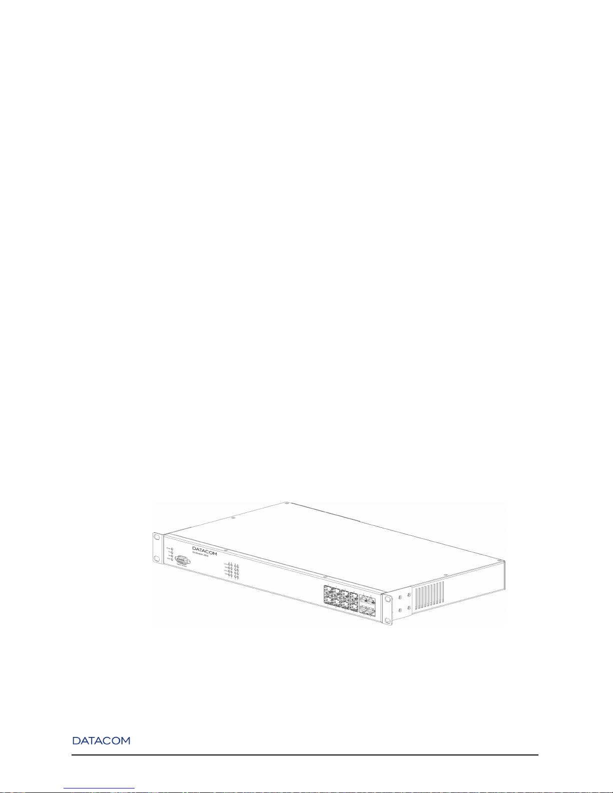
1-1. Overview of the DmSwitch 2000 G1 ...................................................................................................1
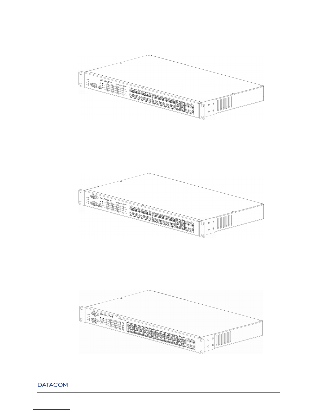
1-2. Overview of the DmSwitch 3000 F1....................................................................................................2
1-3. Overview of the DmSwitch 3000 F2....................................................................................................2
1-4. Overview of the DmSwitch 3000 F3....................................................................................................2
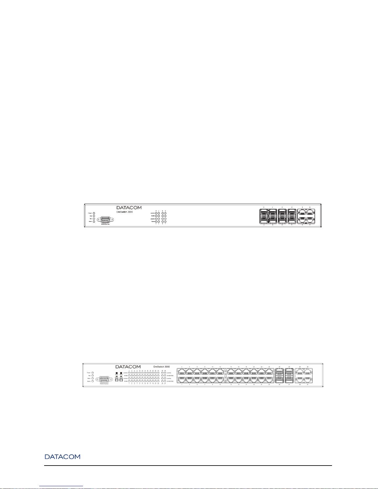
1-5. DmSwitch 2000 G1 Front Panel ..........................................................................................................3
1-6. DmSwitch 3000 F1 Front Panel...........................................................................................................3
1-7. DmSwitch 3000 F2 Front Panel...........................................................................................................4
1-8. DmSwitch 3000 F3 Front Panel...........................................................................................................4
1-9. DmSwitch 3000 System LEDs Location..............................................................................................4
1-10. Port LEDs Location............................................................................................................................5
1-11. Console and Alarm Port Pins Order...................................................................................................6
1-12. Stacking Buttons Location .................................................................................................................8
1-13. DmSwitch F1 Rear Panel...................................................................................................................8
1-14. DmSwitch F2 Rear Panel...................................................................................................................9
v

1-15. DmSwitch F3 Rear Panel...................................................................................................................9
2-1. Rear Pannel with Power Supplies Connectors ...................................................................................11
2-2. Power Supply Rear Panel ...................................................................................................................12
3-1. Rack Mounting...................................................................................................................................15
3-2. DmSwitch F1 Power Connectors .......................................................................................................16
3-3. DmSwitch F2 Power Connectors .......................................................................................................17
3-4. AC/DC Power Suply Connector.........................................................................................................17
4-1. SFP Module Installation.....................................................................................................................19
4-2. Stacking Cable Connection................................................................................................................20
vi
Chapter 1. Introduction
1.1. Overview
DATACOM DmSwitch is a line of Metro Ethernet Switches with L2 and L3 wire-speed comutation capability, MPLS features, that allow its utilization as a Label Edge Router, and many QoS L2-L7 facilities,
ensuring bandwidth control and priority management. It is composed by the 2000 and 3000 families.
DmSwitch 2000 is a family of standalone manageable switches composed by the 2204G1 and 2304G1
models. They are equipped with 4 100BASE-FX and 4 GBE combo ports (10/100/1000Base-T or SFP).
DmSwitch 3000 is a family of stackable manageable switches composed by the 3224F1, 3324F1, 3224F2,
3324F2, 3224F3 and 3324F3 models. Their stacking ports allow the connection of up to eight switches in a
stack configuration. They can also be used in standalone mode. The 3224F1, 3324F1, 3224F2 and 3324F2
versions are equipped with 24 10BASE-T/100BASE-TX and 4 GBE combo ports (10/100/1000Base-T or
SFP), while the 3224F3 and 3324F3 versions are equipped with 24 100BASE-FX and 4 GBE combo ports
(10/100/1000Base-T or SFP).
All switch models use unshielded twisted pair (UTP) cable ports and Auto MDI/MDI-X, allowing the use
of either straight or crossover twisted-pair cables. It means the switch can be used to connect to other
switches, hubs, routers, PCs and many other networking equipments.
Both 2000 and 3000 families switches can be managed through DmView, Telnet/SSH, Web or SNMP.
Figure 1-1. Overview of the DmSwitch 2000 G1
1
Chapter 1. Introduction
Figure 1-2. Overview of the DmSwitch 3000 F1
Figure 1-3. Overview of the DmSwitch 3000 F2
Figure 1-4. Overview of the DmSwitch 3000 F3
2
Chapter 1. Introduction
1.2. Front Panel Description
1.2.1. Front Panel Overview
1.2.1.1. DmSwitch 2000
The front panel of the DmSwitch 2000G1 contains 4 100BASE-FX ports, 4 10/100/1000Base-T/SFP
combo ports and a RS-232 console port.
Figure 1-5. DmSwitch 2000 G1 Front Panel
1.2.1.2. DmSwitch 3000
The front panel of the DmSwitch 3000F1 contains 24 10BASE-T/100BASE-TX ports, 4
10/100/1000Base-T/SFP combo ports, an RS-232 console port and two buttons for changing stacking
options.
Figure 1-6. DmSwitch 3000 F1 Front Panel
3
Chapter 1. Introduction
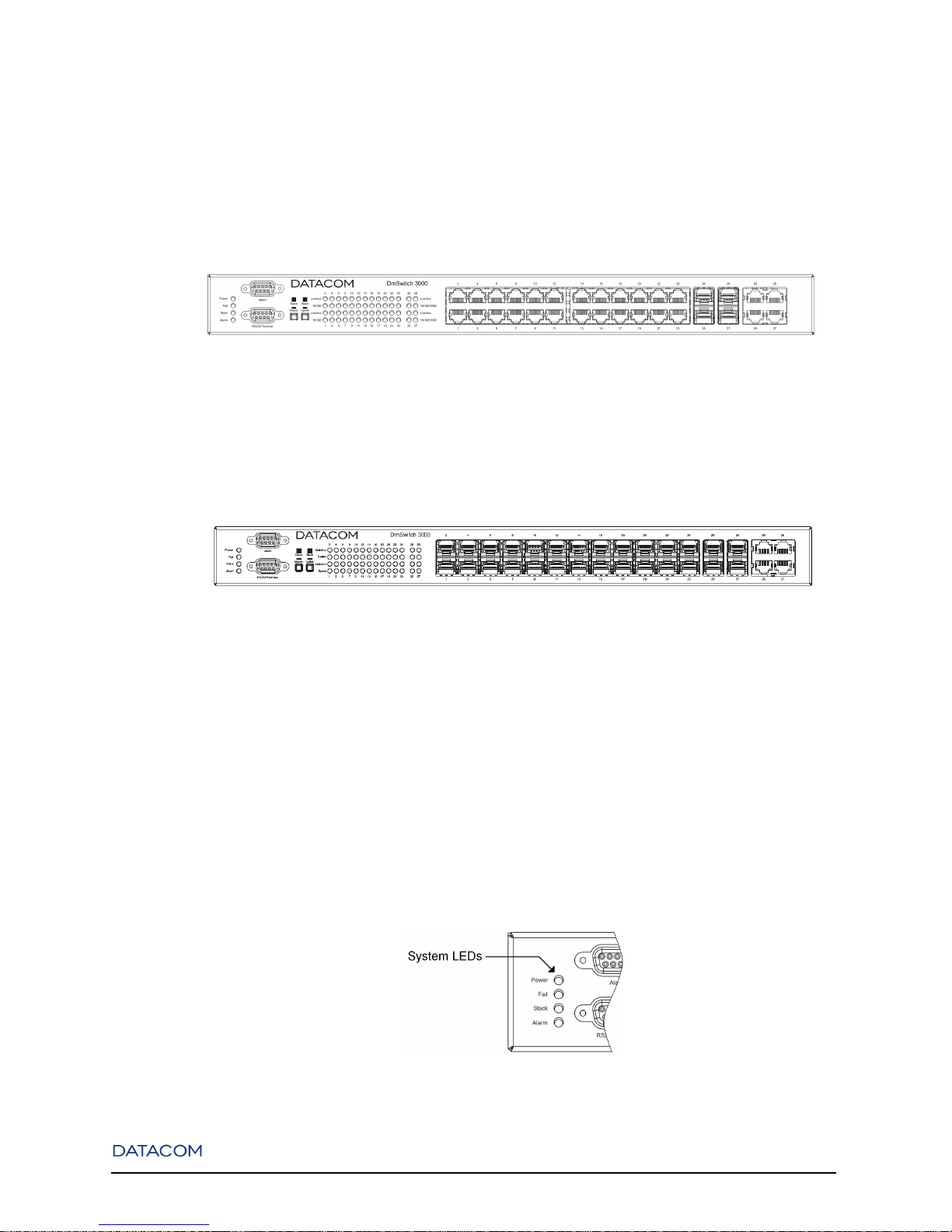
The front panel of the DmSwitch 3000F2 contains 24 10BASE-T/100BASE-TX ports, 4
10/100/1000Base-T/SFP combo ports, an RS-232 console port, an alarm port and two buttons for
changing stacking options.
Figure 1-7. DmSwitch 3000 F2 Front Panel
The front panel of the DmSwitch 3000F3 contains 24 100BASE-FXSFPports, 4 10/100/1000Base-T/SFP
combo ports, an RS-232 console port, an alarm port and two buttons for changing stacking options.
Figure 1-8. DmSwitch 3000 F3 Front Panel
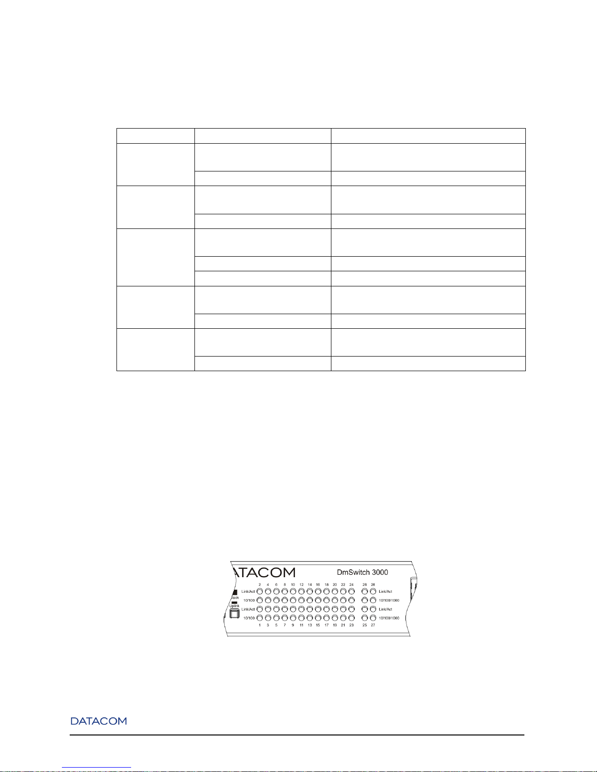
1.2.2. System Status LEDs
The System Status LEDs on the front panel can be used to monitor system activity. Following Figure
shows where the leds are located and the next table indicates the system status acording to each led’s
condition.
Figure 1-9. DmSwitch 3000 System LEDs Location
4
Chapter 1. Introduction
Table 1-1. System LEDs
LED CONDITION STATUS
Power ON System is powered on
OFF System is powered off
Fail ON Indicates hardware failure
OFF System is operating normally
Stack * Blinking Switch is operating in stack mode (master)
ON Switch is operating in stack mode (slave)
OFF Switch is operating in standalone mode
Sys** ON System is booting
OFF System is ready
Alarm ON System Alarm is active
OFF System Alarm is inactive
• * valid only for DmSwitch 3000 family.
• ** valid only for DmSwitch 2000 family.
1.2.3. Port Leds
Port LEDs indicate data activity and speed on each port. Their location is shown in the next Figure and
their status on the table below.
Figure 1-10. Port LEDs Location
5
 Loading...