

Page 1
ADMINISTRATION-MANUAL
GPON - ONU
DM984-100B
Page 2

DM984 product family CONTENTS
Contents
1 Revision History 8
2 Legal notice 9
3 Warranty 10
4 Acronyms 11
5 About 14
6 DM984-100B at a Glance 15
6.1 LEDs . . . . . . . . . . . . . . . . . . . . . . . . . . . . . . . . 16
6.1.1 Overview . . . . . . . . . . . . . . . . . . . . . . . . . . 16
6.1.2 Descriptions . . . . . . . . . . . . . . . . . . . . . . . . 16
6.2 Backside Description . . . . . . . . . . . . . . . . . . . . . . . . 17
6.2.1 RESET-Button . . . . . . . . . . . . . . . . . . . . . . . 17
6.2.2 WPS-Button . . . . . . . . . . . . . . . . . . . . . . . . 17
6.3 Specifications . . . . . . . . . . . . . . . . . . . . . . . . . . . 18
6.3.1 Power supply . . . . . . . . . . . . . . . . . . . . . . . . 18
6.3.2 Dimensions . . . . . . . . . . . . . . . . . . . . . . . . . 18
6.3.3 Management . . . . . . . . . . . . . . . . . . . . . . . . 18
6.3.4 Operating Conditions . . . . . . . . . . . . . . . . . . . 19
6.3.5 Features . . . . . . . . . . . . . . . . . . . . . . . . . . 19
7 Introduction 22
7.1 Physical Specifications . . . . . . . . . . . . . . . . . . . . . . . 22
7.2 T-CONTs . . . . . . . . . . . . . . . . . . . . . . . . . . . . . . 23
7.3 GEM-Port . . . . . . . . . . . . . . . . . . . . . . . . . . . . . 24
8 Physical Setup 25
8.1 Overview . . . . . . . . . . . . . . . . . . . . . . . . . . . . . . 25
204.4288.00
DATACOM
Page 3

DM984 product family CONTENTS
8.2 IP Multiservice Access Platform (IPSAN) . . . . . . . . . . . . . 25
9 Operation with OLTs from other vendors 26
9.1 Registration and Configuration . . . . . . . . . . . . . . . . . . 26
9.2 Checking the Firmware version . . . . . . . . . . . . . . . . . . 26
9.3 Upgrading the Firmware . . . . . . . . . . . . . . . . . . . . . . 26
10 First Steps with IPSAN 27
10.1 Initial Connection . . . . . . . . . . . . . . . . . . . . . . . . . 27
10.2 Working with the CLI . . . . . . . . . . . . . . . . . . . . . . . 28
10.3 Saving configurations . . . . . . . . . . . . . . . . . . . . . . . 29
10.4 Marking Configurations for Startup . . . . . . . . . . . . . . . . 30
10.5 Rebooting the Equipment . . . . . . . . . . . . . . . . . . . . . 30
10.6 Setup of Management Access via Telnet . . . . . . . . . . . . . 30
10.7 Setup of Management Access via SSH . . . . . . . . . . . . . . 31
11 IPSAN Configuration 33
11.1 ONU Registration . . . . . . . . . . . . . . . . . . . . . . . . . 33
11.2 ONU status checking . . . . . . . . . . . . . . . . . . . . . . . 35
11.3 Checking the Firmware version of the ONU . . . . . . . . . . . . 36
11.4 Checking allocated bandwidth . . . . . . . . . . . . . . . . . . . 37
11.5 ONU Firmware upgrade . . . . . . . . . . . . . . . . . . . . . . 37
11.6 Profile Management . . . . . . . . . . . . . . . . . . . . . . . . 39
11.6.1 ONU-Profile . . . . . . . . . . . . . . . . . . . . . . . . 39
11.6.2 SLA-Profile . . . . . . . . . . . . . . . . . . . . . . . . . 41
11.6.3 Checking allocated bandwidth in more detail . . . . . . . 42
11.6.4 VP-SVC-Profile . . . . . . . . . . . . . . . . . . . . . . 42
11.6.5 TCONT-VP-BIND-Profile . . . . . . . . . . . . . . . . . 43
11.6.6 FLOW-Profile . . . . . . . . . . . . . . . . . . . . . . . 45
11.7 VLAN Translation Rules . . . . . . . . . . . . . . . . . . . . . . 47
11.7.1 VLAN Rules for Single Tagging Operations . . . . . . . . 47
11.7.2 VLAN Rules for Double Tagging Operations . . . . . . . 50
11.7.3 Setting the VLAN TPID . . . . . . . . . . . . . . . . . . 51
11.8 Additional ONU Configuration . . . . . . . . . . . . . . . . . . . 51
11.8.1 Assigning VLAN rules . . . . . . . . . . . . . . . . . . . 52
11.8.2 Assigning Native VLANs . . . . . . . . . . . . . . . . . . 52
11.8.3 Configuring the IP Whitelist . . . . . . . . . . . . . . . . 54
11.8.4 Configuration of an IP Address . . . . . . . . . . . . . . 55
11.8.5 Configuration of a Default Gateway . . . . . . . . . . . . 55
11.9 Configuring the Uplink Interface . . . . . . . . . . . . . . . . . . 56
11.10Configuring the VLAN Interface . . . . . . . . . . . . . . . . . . 57
DATACOM
204.4288.00
Page 4

DM984 product family CONTENTS
11.11IGMP-Controlled Multicast . . . . . . . . . . . . . . . . . . . . 58
12 Configuration Guides 61
12.1 Simple Connection with Single Tagged VLAN Setup . . . . . . . 61
12.2 Multiple VLANs and T-CONTs with different Bandwidths Setup . 62
12.3 VLAN Translation Setup . . . . . . . . . . . . . . . . . . . . . . 63
12.4 IGMP Setup . . . . . . . . . . . . . . . . . . . . . . . . . . . . 64
13 Examples 65
13.1 Simple Connection with Single Tagged VLAN . . . . . . . . . . . 65
13.2 Multiple VLANs and T-CONTs with different Bandwidths . . . . 66
13.3 VLAN Translation Setup . . . . . . . . . . . . . . . . . . . . . . 67
13.4 IGMP Setup . . . . . . . . . . . . . . . . . . . . . . . . . . . . 68
14 Supported MEs 70
14.1 Overview . . . . . . . . . . . . . . . . . . . . . . . . . . . . . . 70
14.2 Managed Entity Description . . . . . . . . . . . . . . . . . . . . 73
14.2.1 802.1p Mapper Service Profile . . . . . . . . . . . . . . . 73
14.2.2 ANI-G . . . . . . . . . . . . . . . . . . . . . . . . . . . 73
14.2.3 Attribute . . . . . . . . . . . . . . . . . . . . . . . . . . 74
14.2.4 Authentication Security Method . . . . . . . . . . . . . . 74
14.2.5 Cardholder . . . . . . . . . . . . . . . . . . . . . . . . . 75
14.2.6 Circuit Pack . . . . . . . . . . . . . . . . . . . . . . . . 75
14.2.7 Dot1 Rate Limiter . . . . . . . . . . . . . . . . . . . . . 76
14.2.8 Dot1X Port Extension Package . . . . . . . . . . . . . . 76
14.2.9 Equipment Extension Package . . . . . . . . . . . . . . . 77
14.2.10 Ethernet Frame Extended Performance Monitoring His-
tory Data . . . . . . . . . . . . . . . . . . . . . . . . . . 77
14.2.11 Ethernet Frame Performance Monitoring History Data Down-
stream . . . . . . . . . . . . . . . . . . . . . . . . . . . 78
14.2.12 Ethernet Frame Performance Monitoring History Data Up-
stream . . . . . . . . . . . . . . . . . . . . . . . . . . . 78
14.2.13 Ethernet Performance Monitoring History Data . . . . . . 79
14.2.14 Ethernet Performance Monitoring History Data 2 . . . . . 80
14.2.15 Ethernet Performance Monitoring History Data 3 . . . . . 80
14.2.16 Extended VLAN Tagging Operation Configuration Data . 81
14.2.17 FEC Performance Monitoring History Data . . . . . . . . 82
14.2.18 GAL Ethernet Performance Monitoring History Data . . . 82
14.2.19 GAL Ethernet Profile . . . . . . . . . . . . . . . . . . . 83
14.2.20 GEM Interworking Termination Point (GEM ITP) . . . . 83
14.2.21 GEM Port Network CTP . . . . . . . . . . . . . . . . . . 84
DATACOM
204.4288.00
Page 5

DM984 product family CONTENTS
14.2.22 GEM Port Network CTP Performance Monitoring History
Data . . . . . . . . . . . . . . . . . . . . . . . . . . . . 84
14.2.23 GEM Port Performance Monitoring History Data . . . . . 85
14.2.24 IP Host Config Data . . . . . . . . . . . . . . . . . . . . 85
14.2.25 IP Host Performance Monitoring History Data . . . . . . 86
14.2.26 IPv6 Host Config Data . . . . . . . . . . . . . . . . . . . 86
14.2.27 Large String . . . . . . . . . . . . . . . . . . . . . . . . 86
14.2.28 MAC Bridge Configuration Data . . . . . . . . . . . . . 87
14.2.29 MAC Bridge Performance Monitoring History Data . . . . 87
14.2.30 MAC Bridge Port Bridge Table Data . . . . . . . . . . . 88
14.2.31 MAC Bridge Port Configuration Data . . . . . . . . . . . 88
14.2.32 MAC Bridge Port Designation Data . . . . . . . . . . . . 89
14.2.33 MAC Bridge Port Filter Preassign Data . . . . . . . . . . 89
14.2.34 MAC Bridge Port Filter Table Data . . . . . . . . . . . . 89
14.2.35 MAC Bridge Port Performance Monitoring History Data . 90
14.2.36 MAC Bridge Service Profile . . . . . . . . . . . . . . . . 90
14.2.37 Managed Entity . . . . . . . . . . . . . . . . . . . . . . 91
14.2.38 Multicast GEM Interworking Termination Point . . . . . . 91
14.2.39 Multicast Operations Profile . . . . . . . . . . . . . . . . 91
14.2.40 Multicast Subscriber Config Info . . . . . . . . . . . . . . 92
14.2.41 Multicast Subscriber Monitor . . . . . . . . . . . . . . . 93
14.2.42 Network Address . . . . . . . . . . . . . . . . . . . . . . 93
14.2.43 OLT-G . . . . . . . . . . . . . . . . . . . . . . . . . . . 93
14.2.44 OMCI . . . . . . . . . . . . . . . . . . . . . . . . . . . 94
14.2.45 ONU Data . . . . . . . . . . . . . . . . . . . . . . . . . 94
14.2.46 ONU Dynamic Power Management Control . . . . . . . . 94
14.2.47 ONU Power Shedding . . . . . . . . . . . . . . . . . . . 95
14.2.48 ONU Remote Debug . . . . . . . . . . . . . . . . . . . . 96
14.2.49 ONU2-G . . . . . . . . . . . . . . . . . . . . . . . . . . 96
14.2.50 ONU-G . . . . . . . . . . . . . . . . . . . . . . . . . . . 97
14.2.51 Physical Path Termination Point Ethernet UNI (PPTP
Ethernet UNI) . . . . . . . . . . . . . . . . . . . . . . . 97
14.2.52 Port Mapping Package . . . . . . . . . . . . . . . . . . . 98
14.2.53 Priority Queue . . . . . . . . . . . . . . . . . . . . . . . 98
14.2.54 Software Image . . . . . . . . . . . . . . . . . . . . . . . 99
14.2.55 T-CONT . . . . . . . . . . . . . . . . . . . . . . . . . . 99
14.2.56 TCP/UDP Config Data . . . . . . . . . . . . . . . . . . 100
14.2.57 TCP/UDP Performance Monitoring History Data . . . . . 100
14.2.58 Threshold Data 1 . . . . . . . . . . . . . . . . . . . . . 101
14.2.59 Threshold Data 2 . . . . . . . . . . . . . . . . . . . . . 101
14.2.60 Traffic Descriptor . . . . . . . . . . . . . . . . . . . . . 101
DATACOM
204.4288.00
Page 6

DM984 product family CONTENTS
14.2.61 Traffic Scheduler . . . . . . . . . . . . . . . . . . . . . . 102
14.2.62 UNI-G . . . . . . . . . . . . . . . . . . . . . . . . . . . 102
14.2.63 Virtual Ethernet interface point . . . . . . . . . . . . . . 102
14.2.64 VLAN Tagging Filter Data . . . . . . . . . . . . . . . . . 103
14.2.65 VLAN Tagging Operation Configuration Data . . . . . . 103
DATACOM
204.4288.00
Page 7

DM984 product family LIST OF FIGURES
List of Figures
6.1 DM984 . . . . . . . . . . . . . . . . . . . . . . . . . . . . . . . 15
6.2 Topview . . . . . . . . . . . . . . . . . . . . . . . . . . . . . . 16
6.3 View of DM984-100 interfaces . . . . . . . . . . . . . . . . . . . 17
7.1 Possible Topology for GPON . . . . . . . . . . . . . . . . . . . 22
7.2 GPON Architectures . . . . . . . . . . . . . . . . . . . . . . . . 23
11.1 Relations of GPON-Profiles . . . . . . . . . . . . . . . . . . . . 39
DATACOM
204.4288.00
Page 8

DM984 product family CHAPTER 1. REVISION HISTORY
1. Revision History
Version Comments
v1.1.0 Release version
DATACOM
204.4288.00
Page 9

DM984 product family CHAPTER 2. LEGAL NOTICE
2. Legal notice
Although every precaution has been taken in the preparation of this document,
DATACOM takes no responsibility for possible errors or omissions, and it will
accept no obligation for damages resulting from the use of the information contained in this manual. The specifications provided in this manual are subject to
changes without notice, and they will not be recognized as any kind of contract.
Any quotes in this document are property of their respective third party owners
and come without warranty.
c
2015 DATACOM - All rights reserved.
DATACOM
204.4288.00
Page 10

DM984 product family CHAPTER 3. WARRANTY
3. Warranty
This product is warranted against material and workmanship defects for the period specified in the sales invoice. The warranty only includes the repair and
replacement of defective components and parts without any resulting burden to
the customer. Defects resulting from the following are not covered: improper
use of device, faulty electrical power network, nature-related events (lightning
discharges, for instance), failure in devices connected to this product, installations with improper grounding or repairs made by personnel not authorized by
DATACOM. This warranty does not cover repairs at the customer’s facilities.
Equipment must be forwarded for repairs to DATACOM.
DATACOM
204.4288.00
Page 11

DM984 product family CHAPTER 4. ACRONYMS
4. Acronyms and declarations
ANI-G (Access Node Interface-GPON)
CLI (Command Line Interface) – User Interface where commands are issued in
form of text. In the context of this manual this term is referring to the IPSAN’s
Command Line Interface unless specified otherwise.
CTP (Connection Termination Point)
DBA (Dynamic Bandwidth Allocation) - standardized mechanism for bandwidth
management
DFB (Distributed Feedback Laser)
DTMF (Dual-tone multi-frequency)
FEC (Forward Error Correction)
FTTB/C (Fiber-to-the-Building/Curb) – Common GPON architecture where the
service is provided for one or more buildings
FTTCab (Fiber-to-the-Cabinet) – Common GPON architecture which is similar to FTTB/C but the actual end of the GPON network is considered to be
nearer at the service provider
FTTH (Fiber-to-the-Home) – Common GPON architecture where the service
is provided for a single customer
GEM-Port (GPON encapsulation method port) – Used to differentiate between
data inside of a T-CONT
GPON (Gigabit-capable Passive Optical Network) – refer to Introduction into
204.4288.00
DATACOM
Page 12

DM984 product family CHAPTER 4. ACRONYMS
GPON for further information
IPSAN (IP Multiservice Access Platform) – DM4600 Product Line including support for GPON and many other Services
ITP (Interworking Termintation Point)
MAC (Media Access Control)
ME (Managed Entity) – Specific part of a configuration that is present on the
ONU. A managed entity is configured by one or more OMCI messages.
ODN (Optical Distribution Network) – physical network connecting OLT and
ONU
OFE (Optical Fiber Enclosure) - Underside Enclosure where the fiber is stored
OLT (Optical Line Termination) – Formal declaration of a configuring hardware/software in a GPON network
OMCI (Optical network unit Management and Control Interface) – Used by the
OLT to configure the ONU and watch its behaviour
ONT (Optical Network Termination) – see ONU
1
ONU (Optical Network Unit) – Formal declaration of the user node hardware/software in a GPON network that will be configured by an OLT
PPTP (Physical Path Termination Point) - for example an Ethernet interface
QoS (Quality of Service) – Queuing protocol for preferential data handling
SFP (Small form-factor pluggable) – Used to enable different types of physical connections depending on the customer needs
SNI (Service Node Interface) – Interfaces at the OLT used by the service provider
to deliver the data to a user
1
ONU and ONT is often considered to be the same. This practice is followed in this
manual. However, there is a difference between ONU and ONT, as ONT describes only the
GPON part of a user device. To avoid confusion between the terms or with the acronym OLT
the device is called ONU further on.
DATACOM
204.4288.00
Page 13

DM984 product family CHAPTER 4. ACRONYMS
T-CONT (Transmission Containers) – Used for assignments of specific services
(e.g. different bandwidths)
UNI (User Network Interface) – Interfaces at the ONU used by a user to access the GPON network
DATACOM
204.4288.00
Page 14

DM984 product family CHAPTER 5. ABOUT
5. About this Manual
This manual is supposed to help network administrators to provision the DM984
family for use in a GPON network. It also aims to help with administration of
GPON networks considering different OLTs, while the focus is on the DM4650
(IPSAN - IP Multiservice Access Platform). Further it features full example configurations for the IPSAN as well as common scenarios which are described as
configuration guides. Please be advised that this manual is not supposed to be
an administration guide to the IPSAN. However, for a full guide to all of the
GPON features of the IPSAN as well as other functionalities please refer to the
dedicated IPSAN’s User Manual.[1]
In order to use this manual, fundamental knowledge about network processes
is mandatory.
DATACOM
204.4288.00
Page 15

DM984 product family CHAPTER 6. DM984-100B AT A GLANCE
6. DM984-100B at a Glance
The DM984-100B GPON ONU (optical network unit) family offers access solution for high speed fiber optic. It delivers triple-play services for business and
residential users. The Ethernet data is transported transparently by the GPON
link and delivered to a unit line termination (OLT, Optical Line Termination),
like the DM4610 OLT and the DM4600 – 8-GPON, a GPON interface board for
DATACOM’s DM4600 – IPSAN family.
DATACOM
Figure 6.1: DM984
204.4288.00
Page 16

DM984 product family CHAPTER 6. DM984-100B AT A GLANCE
6.1 LEDs
6.1.1 Overview
Figure 6.2: LED view of DM984
6.1.2 Descriptions
POWER
Behavior Event
Constant green ONU is powered on
Constant off ONU is powered off
ALARM
Not in use on this product model.
PON
Behavior Event
Constant green Connection to OLT established
Constant off No connection to OLT
ETH1
Behavior Event
Constant green Connected but no Ethernet traffic
Constant off No Ethernet connection
DATACOM
204.4288.00
Page 17

DM984 product family CHAPTER 6. DM984-100B AT A GLANCE
Green blinking Under Ethernet traffic
ETH2
Not in use on this product model.
ETH3
Not in use on this product model.
ETH4
Not in use on this product model.
TEL
Not in use on this product model.
WIFI
Not in use on this product model.
6.2 Backside Description
Figure 6.3: Backside of DM984-100
6.2.1 RESET-Button
Not in use on this product model.
6.2.2 WPS-Button
Not in use on this product model.
DATACOM
204.4288.00
Page 18

DM984 product family CHAPTER 6. DM984-100B AT A GLANCE
6.3 Specifications
The DM984 GPON ONU is an optical network terminal that offers one Gigabit
Ethernet LAN interface and an integrated OFE (optional).
It has the ability to add, remove and modify VLANs, supports multicast traffic (e.g. video transport) and has QoS functionality.
6.3.1 Power supply
The DM984 uses an external power source with the following characteristics.
• Input: 100Vac to 240Vac Full Range (automatic selection), 50Hz to 60Hz
• Output: 12Vdc 500mA
• Device consumption: <4W
Attention: Use only the power supply shipped with the DM984-100B. The
device may experience severe damage if another power supply is used.
6.3.2 Dimensions
• The DM984 GPON ONU is presented in a desktop enclosure
– With integrated OFE, it measures 190mm in width, 160mm in depth
and 46mm in height, including its rubber feet.
– Without integrated OFE, it measures 180mm in width, 160mm in
depth and 36mm in height.
6.3.3 Management
• Uses OMCI protocol for management, according to ITU-T G.988[4]
• Allows remote firmware upgrade;
• Allows storage of two firmware images with software integrity check and
possible rollback
DATACOM
204.4288.00
Page 19

DM984 product family CHAPTER 6. DM984-100B AT A GLANCE
6.3.4 Operating Conditions
• Operating Temperature: 0◦C to 45◦C
• Operating Humidity: 5% - 95% non-condensing
6.3.5 Features
GPON Interface (WAN)
• Compliant with ITU-T G.984[3]
• Connector SC/APC
• Supports burst mode of 1.244 Gbit/s Upstream
• Supports burst mode of 2.488 Gbit/s Downstream
• Performance Monitoring
• DFB Laser, according to ITU-T G.984.2[2] AMD1
– Average optical transmit power: Between +0.5 dBm and +5 dBm
– Receive Sensitivity: At least -27 dBm
– Overload reception:-8 dBm
(Signal should not be higher than -8dBm otherwise it will not work
properly)
• Wavelengths:
– Upstream: 1310 nm
– Downstream: 1490 nm
• Laser Class I
• Dying Gasp
• Up to 8 T-CONTs and 32 GEM ports possible
• VLAN or VLAN plus 802.1p mapping to GEM ports
• Upstream SP, WRR, SP+WRR scheduling
• Flexible mapping between GEM Ports and T-CONTs
DATACOM
204.4288.00
Page 20

DM984 product family CHAPTER 6. DM984-100B AT A GLANCE
• Activation by automatic discovery of serial number and password as ITU-T
G.984.3[5]
• AES-128 downstream decryption
• DBA (DBRU)
• Bidirectional FEC (Forward Error Correction)
• VLAN plus 802.1p QoS for dropping un-allowed p-bits
• VLAN plus 802.1p Rate limiting
Gigabit Ethernet Interface (LAN)
• RJ45 Connectors
• 10/100/1000 Base-T interfaces
• Auto negotiation or manual configuration
• MDI / MDIX
• Bridging (802.1D)
Virtual Bridge
• Adding or removing VLAN tags
• VLAN stacking (QinQ) and VLAN translation
• Classes of service based on ports, VLAN ID, 802.1p or a combination
• Jumbo frames up to 9kB
• MAC learning
• VLANs 1-4094
• Rate limiting per VLAN and 802.1p combination
Broadcast and Multicast
• IGMPv2/v3 snooping
• Broadcast and multicast rate limit
• 50 multicast groups
DATACOM
204.4288.00
Page 21

DM984 product family CHAPTER 6. DM984-100B AT A GLANCE
Management and Configuration
• Advanced PLOAM functions
• OMCI
• Firmware image uploads through OMCI according to G.988[4]
• Dual image
• Remote reboot
DATACOM
204.4288.00
Page 22
DM984 product family CHAPTER 7. INTRODUCTION
7. Introduction into GPON
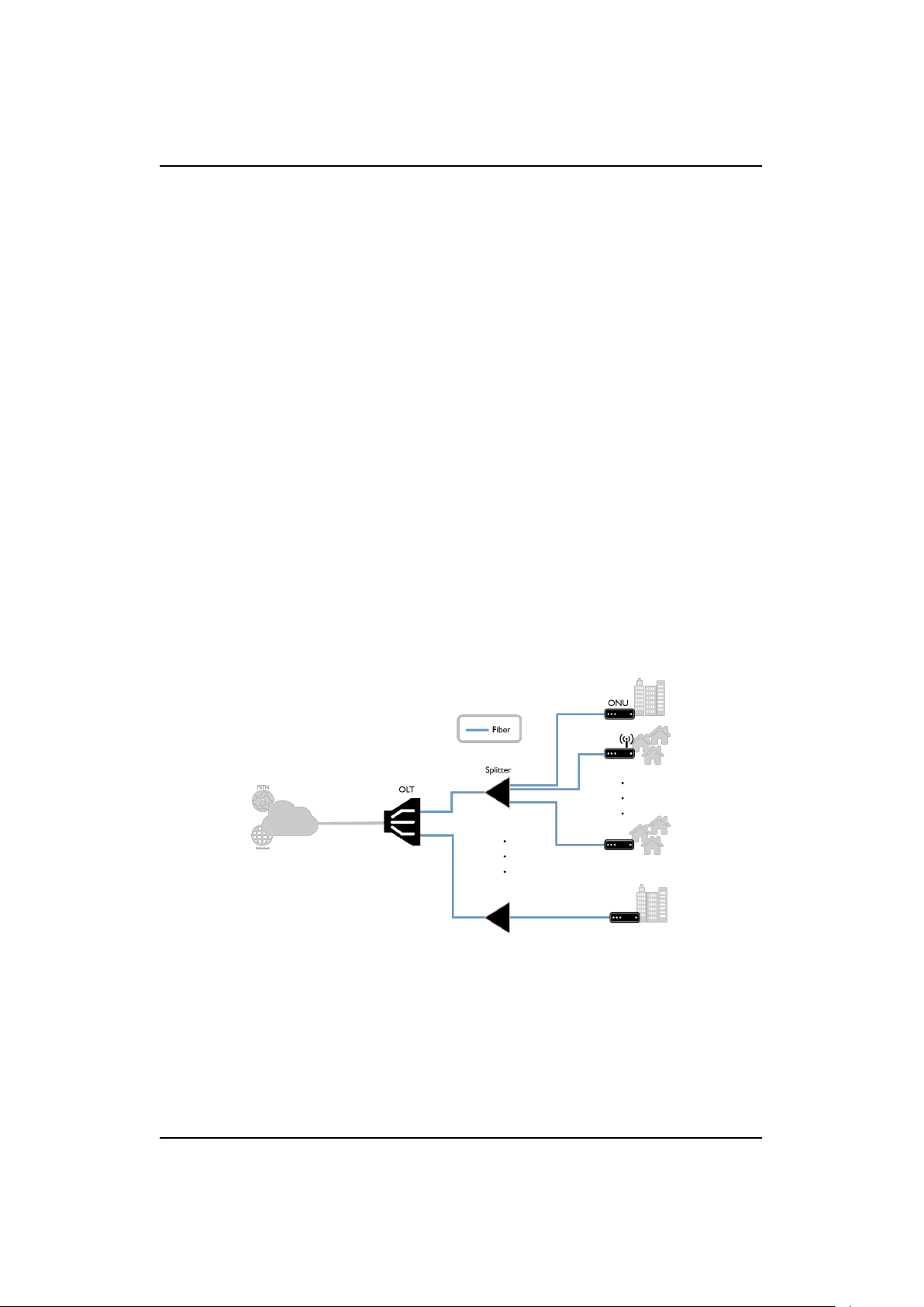
The main characteristics of Passive Optical Networks (PON) is that there are no
electrical components in use for signal distribution. This architecture is mainly
used as a solution for access to the last mile, leading optical fiber cabling and
signals nearest to end user. A PON system has the ability to deliver high speed
rates for broadband access.
The first PON was based on ATM (called APON, now renamed to broadband
or BPON) and it has evolved to today’s dominants Gigabit PON (GPON) and
Ethernet PON (EPON). All of these optical technologies create split multi-site
connection paths, they are built using a similar topology, and components like
shown by Figure 7.1.
Figure 7.1: Possible Topology for GPON
7.1 Physical Specifications
GPON is a technology used to realize FTTx (e.g. Fiber-to-the-Home) architectures (See Figure 7.2). A network that uses GPON technology basically consists
204.4288.00
DATACOM
Page 23
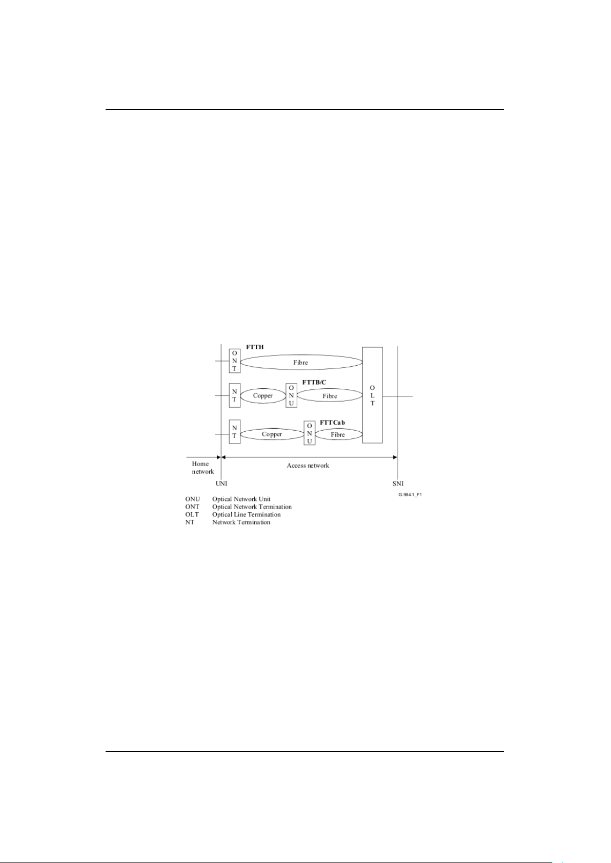
DM984 product family CHAPTER 7. INTRODUCTION
of two main parts, the OLT and one or more ONUs. In general, all operations
to provision a GPON are issued at the OLT and sent via OMCI messages to the
ONU. An ODN connects the OLT and the ONUs.
As defined in the ITU-T G.984.1 standard[3] GPON devices are capable of processing traffic up to 2.488 Gbit/s in downstream and 1.244 Gbit/s in upstream
direction.
The physical reach is the maximum physical distance between the ONU/ONT
and the OLT. In GPON, two options are defined for the physical reach: 10 km
and 20 km. It is assumed that 10 km is the maximum distance over which FP-LD
can be used. However, this ONU uses a DFB laser diode, so it is able to operate
at a maximum distance of 20 km.
Figure 7.2: GPON Architectures[3]
7.2 Transmission Containers (T-CONTs)
A transmission container or T-CONT is a group of logical connections. For one
ONU there are multiple T-CONTs possible. The number of supported T-CONTs
depends on the ONU software. One T-CONT has a specific bandwidth allocation.
Each T-CONT is supposed to provide different services.
204.4288.00
DATACOM
Page 24

DM984 product family CHAPTER 7. INTRODUCTION
7.3 GPON encapsulation method port (GEM-Port)
GEM is a data frame transport scheme used in GPON systems which is connectionoriented and supports fragmentation of user data frames into variable-sized transmission fragments. One or more GEM-Ports on the other hand are a logical
gateways for specific user data flows that are assigned to a specific T-CONT. So
it is possible to differentiate between user data within the same service that is
represented by a T-CONT.
DATACOM
204.4288.00
Page 25

DM984 product family CHAPTER 8. PHYSICAL SETUP
8. Physical Setup
8.1 Overview
To achieve any GPON setup described in this manual it is assumed that there is
an OLT, which configures the ONU. According to ITU-T G.984.1[3] it is intended
to have a passive fiber connection between the OLT and the ONU. It may include
optical splitters as well as other passive network components. In a typical FTTH
scenario the ONU is connected to the OLT via the ODN and the customer
may connect it to his local network. The OLT must also be connected to the
service providers’ network. The setup may vary for different scenarios. For an
introduction into GPON please refer to the chapter Introduction into GPON.
Additionally refer to the manual of the OLT vendor to be sure the ONU is
connected correctly.
8.2 IP Multiservice Access Platform (IPSAN)
In case of using the IPSAN as OLT, there is a dedicated GPON card installed
which is used to connect the ONU via the ODN to a GPON interface at the
GPON card of the IPSAN. Such a GPON interface is also called ponlink in
short which will be the convention in this document. In addition to the ONU
connections, the IPSAN needs at least one more connection, which acts as uplink
to the service providers’ network. Depending on the customers needs, it is also
possible to define more than one uplink. Each of the connections to the IPSAN
may need a specific SFP to connect the cables to the interfaces. The setup for
the scenario with FTTH described above remains the same. Note that the IPSAN
is not only an OLT and may be used for other purposes too. For a full guide to
all of the supported GPON features, as well as other functionalities please refer
to the dedicated IPSAN’s User Manual.[1]
204.4288.00
DATACOM
Page 26

DM984 product family CHAPTER 9. OPERATION WITH OLTS FROM OTHER VENDORS
9. Operation with OLTs from other vendors
9.1 Registration and Configuration
There are two values that are used by the OLT to identify the ONU. The ONU
has a unique serial number and a password. While the password is changeable,
the serial number is not. With these two values the ONU can be registered in 3
different ways.
It can be registered using only the serial number, only the password or the two in
combination. From now on all the work is done on the OLT’s configuration interface. Please refer to the manual of the OLT vendor to ensure proper registration
of the ONU.
9.2 Checking the Firmware version
It is possible to check the firmware version from an OLT’s user interface remotely,
as the ONU is sending its firmware information to the OLT. Please refer to the
manual of the OLT vendor on how check the firmware version with your OLT.
9.3 Upgrading the Firmware
Following the ITU-T G.988[4] the upgrade of the firmware version (also called
software download) is only performed by the OLT. Please refer to the manual of
the OLT vendor to ensure proper upgrade of the firmware.
For a smooth operation of the ONU, please check for firmware updates on a
regular basis and keep the version up to date.
DATACOM
204.4288.00
Page 27

DM984 product family CHAPTER 10. FIRST STEPS WITH IPSAN
10. First Steps with IPSAN
It is possible to connect to the configuration CLI (command line interface)
through serial cables, telnet and SSH. Initially the IPSAN is accessible via the
serial interface only. For security reasons it is recommended to use SSH for any
configuration. The necessary steps to configure SSH are defined in the section
10.1 Initial Connection
The first connection is possible only through the serial interface of the IPSAN. For
this purpose a terminal emulation program, such as Hyperterminal, TeraTerm,
PuTTY or similar is needed. The emulation program needs to be configured like
this:
Baudrate: 115200
Byterate: 8
Stopbits: 1
Paritybit: None
When accessing the CLI a prompt for username should be visible:
DM4650 login:
After that a prompt for the password is shown:
password:
The default values for these are:
Username: admin
Password: admin
After login it is highly recommended to change the password of the admin user.
The password can be changed when using the command passwd.
The following example shows the password changing procedure:
DATACOM
204.4288.00
Page 28

DM984 product family CHAPTER 10. FIRST STEPS WITH IPSAN
DM4650#passwd
Type Old Password
password:
Type New Password
password:
Confirm Password
password:
Password changed sucessfully.
DM4650#
For a guide on how to create more users besides the admin user please refer to
the IPSAN’s User Manual.[1]
10.2 Working with the CLI
To achieve any configuration on the IPSAN it is necessary to go into the so called
configuration menu by typing:
configure
Example:
DM4650#configure
DM4650(config)#
The builtin help can be accessed by pressing ’?’ or issuing the command help.
This is possible at any time when at the IPSAN’s prompt.
The IPSAN supports auto-completion. Based on the example above it is possible
to just type conf and confirm the command with ENTER or complete the command automatically by pressing TAB. This is possible with all commands when
at the IPSAN’s prompt.
Example:
DM4650#conf
DM4650(config)#
When a menu is active, more information about the menu is available by issuing
the following command:
show this
Note:In some menus it isn’t possible to do that, e.g. the configuration menu.
Example:
204.4288.00
DATACOM
Page 29

DM984 product family CHAPTER 10. FIRST STEPS WITH IPSAN
DM4650(unit-gpon-7)#show this
Unit: 7
Authentication method: serial-number
Key exchange interval: 3600
DM4650(unit-gpon-7)#
To exit a menu this command is given:
exit
Example:
DM4650(config)#exit
DM4650#
10.3 Saving configurations
There are two options for saving configurations to the persistent flash storage
of the IPSAN. The first option is in combination with marking it as startupconfiguration and the second option is without marking it as startup configuration. When a configuration is marked as startup-configuration it gets loaded
upon the next startup of the IPSAN.
To save a configuration and mark it for the next startup the following command
must be issued:
copy running-config startup-config <flash-position>
Description of the used parameters:
Name Format Description
<flash-position> Number (1-10) Position where the configuration is stored
Example:
DM4650#copy running-config startup-config 10
Saving running configuration in flash 10...
DM4650#
To store a configuration without marking it as startup the following command is
given at the standard prompt:
copy running-config flash-config <flash-position>
Description of the used parameters:
DATACOM
204.4288.00
Page 30

DM984 product family CHAPTER 10. FIRST STEPS WITH IPSAN
Name Format Description
<flash-position> Number (1-10) Position where the configuration is stored
Example:
DM4650#copy running-config flash-config 10
Saving running configuration in flash 10...
DM4650#
10.4 Marking Configurations for Startup
To mark a configuration for loading upon the next startup the following command
must be:
select startup-config <flash-position>
Description of the used parameters:
Name Format Description
<flash-position> Number (1-10) Position where the configuration is stored
Example:
DM4650#select startup-config 10
DM4650#
10.5 Rebooting the Equipment
To reboot the IPSAN the following command is issued:
reboot
Example:
DM4650#reboot
Please save startup configuration.
Are you sure you want to reboot the system? <y/N> y
Connection closed by foreign host.
10.6 Setup of Management Access via Telnet
The IPSAN has a dedicated management Ethernet interface, which is used for
configuration purposes.
DATACOM
204.4288.00
Page 31

DM984 product family CHAPTER 10. FIRST STEPS WITH IPSAN
The following steps are done in the configuration menu. First it is necessary
to go into the menu of the management Ethernet.
interface mgmt-eth
Then an IP address is configured.
ip address <ip-address>/<mask>
Description of the used parameters:
Name Format Description
<ip-address> IPv4 Address IP address of the management Ethernet
<mask> Number (4-30) Subnet mask in bit
In some cases it might be necessary to configure static routes to ensure proper
connection to the IPSAN. For this purpose the following command must issued.
ip route <network-address>/<mask> <gateway>
Description of the used parameters:
Name Format Description
<ip-address> IPv4 Network IP address of the management Ethernet
<mask> Number (4-30) Subnet mask in bit
<gateway> IPv4 Address Default Gateway
Note: In order to use this feature, fundamental knowledge about static IPv4
routing is necessary.
10.7 Setup of Management Access via SSH
The IPSAN has a dedicated management Ethernet interface which is used for
configuration purposes.
The following steps are done in the configuration menu. First it is necessary
to go into the menu of the management Ethernet.
interface mgmt-eth
Then an IP address is configured.
ip address <ip-address>/<mask>
Description of the used parameters:
DATACOM
204.4288.00
Page 32

DM984 product family CHAPTER 10. FIRST STEPS WITH IPSAN
Name Format Description
<ip-address> IPv4 Address IP address of the management Ethernet
<mask> Number (4-30) Subnet mask in bit
In some cases it might be necessary to configure static routes to ensure proper
connection to the IPSAN. For this purpose the following command must be
issued.
ip route <network-address>/<mask> <gateway>
Description of the used parameters:
Name Format Description
<ip-address> IPv4 Network IP address of the management Ethernet
<mask> Number (4-30) Subnet mask in bit
<gateway> IPv4 Address Default Gateway
Note: In order to use this feature, fundamental knowledge about static IPv4
routing is necessary. The next step is to activate the SSH server. To do so the
following command is issued.
ip ssh server
When it is wanted to deactivate telnet access the following command is issued
additionally.
no telnet server
DATACOM
204.4288.00
Page 33

DM984 product family CHAPTER 11. IPSAN CONFIGURATION
11. IPSAN Configuration
11.1 ONU Registration
The following steps are done in the configuration menu. In order to register
the ONU it is needed to specify the desired authentication method. First it is
necessary to switch to the menu of the GPON unit-card, by typing
unit-gpon <unit>
Description of the used parameters:
Name Format Description
<unit> Number (1-7) Card slot of the plugged in GPON card
In the following example it is assumed that the GPON card is plugged into slot 7.
Example:
DM4650(config)#unit-gpon 7
DM4650(unit-gpon-7)#
The following command is provided to configure the registration method:
authentication-method <method>
In place of the parameter <method> there are 3 different options that can be
picked:
• serial-number
• serial-number-and-password
• password
Now it is necessary to pick one of the options by writing the keyword after the
command and pressing ENTER.
Example with serial number method:
DATACOM
204.4288.00
Page 34

DM984 product family CHAPTER 11. IPSAN CONFIGURATION
DM4650(unit-gpon-7)#authentication-method serial-number
DM4650(unit-gpon-7)#
Before registering an ONU, however, it is necessary to bring up the ponlink the
ONU is connected to. To do that it is necessary to go into the ponlink menu by
typing
interface gpon <unit>/<ponlink>
Description of the used parameters:
Name Format Description
<unit> Number (1-7) Card slot of the plugged-in GPON card
<ponlink> Number (1-8) Ponlink the ONU is connected to
After that the ponlink needs to be brought up by typing
no shutdown
It is possible to check if the IPSAN discovered the serial number of the ONU by
typing
show interfaces gpon <unit>/<ponlink> discovered-onus
Description of the used parameters:
Name Format Description
<unit> Number (1-7) Card slot of the plugged-in GPON card
<ponlink> Number (1-8) Ponlink the ONU is connected to
Note: To register an ONU it isn’t mandatory to discover the ONU first. It
is also possible to configure it in advance and just connect it later on. Once it
gets discovered by the IPSAN it will be registered and configured automatically.
The following steps are done in the configuration menu. To proceed with the
registration procedure it is necessary to go into the menu of the ponlink the ONU
is connected to by typing
interface gpon <unit>/<ponlink>
Description of the used parameters:
Name Format Description
<unit> Number (1-7) Card slot of the plugged-in GPON card
<ponlink> Number (1-8) Ponlink the ONU is connected to
Next the registration procedure is issued with the following command
204.4288.00
DATACOM
Page 35

DM984 product family CHAPTER 11. IPSAN CONFIGURATION
onu <id> <cmd>
In place of <cmd> there are 3 possible command parts:
• serial-number <serial>
• serial-number <serial> password <password>
• password <password>
Name Format Description
<id> Number (1-128) ID of the ONU to be added
<serial> 4 Letters 8 Numbers Unique predefined serial number of the ONU
<password> Alphanumeric (10 char) Preconfigured password of the ONU
Note: When the chosen id is already taken it will change the existing entry.
Example for serial number registration method:
DM4650(config)#interface gpon 7/3
DM4650(config-if-gpon-7/3)#onu 1 serial-number DACM00000000
DM4650(config-if-gpon-7/3/1)#exit
DM4650(config-if-gpon-7/3)#exit
DM4650(config)#
Example for serial number and password registration method:
DM4650(config)#interface gpon 7/3
DM4650(config-if-gpon-7/3)#onu 1 serial-number DACM00000000
,→ password pass123
DM4650(config-if-gpon-7/3/1)#exit
DM4650(config-if-gpon-7/3)#exit
DM4650(config)#
Example for password registration method:
DM4650(config)#interface gpon 7/3
DM4650(config-if-gpon-7/3)#onu 1 password pass123
DM4650(config-if-gpon-7/3/1)#exit
DM4650(config-if-gpon-7/3)#exit
DM4650(config)#
Note:When the registration process is finished the prompt will automatically
switch to the ONU menu.
11.2 ONU status checking
The following command is used in the ONU menu in order to check the status
of the ONU:
DATACOM
204.4288.00
Page 36

DM984 product family CHAPTER 11. IPSAN CONFIGURATION
show this
When performing this command a lot of information is printed out at the command line, regarding whether the ONU is up and active, which profiles are assigned, as well as other ONU characteristics.
Example:
DM4650(config-if-gpon-7/3/2)#show this
Showing ONU 7/3/2
Name:
Serial number: DACM00000000
ONU profile: default
TCONT VP Bind profile: default
Flow profile: default
IP address: 0.0.0.0/0
Default gateway: 0.0.0.0
DHCP: disabled
IP Host VLAN: VLAN=1(0)
Max MAC per eth-uni: 0
Operational state: down (Inactive)
Anti Rogue ONU isolate: disabled
SWDL state: None
Vendor ID:
Version:
Equipment ID:
Active FW: (not valid)
Standby FW: (not valid)
Sub-option mode: both (circuit-id + remote-id)
Allocated bandwidth: 512(fixed), 512(assured+fixed) - kbps
DM4650(config-if-gpon-7/3/2)#
Note: One of the most important items for troubleshooting is the operational
state. When the ONU is fully shutdown it will show ’down (Inactive)’. When the
ONU is fully operational it will show ’up (active)’. When the ONU itself is not
fully operational but the optical connection is (for example after a reboot of the
ONU) it will show ’down (active)’.
11.3 Checking the Firmware version of the ONU
The firmware version is visible when checking the status of the ONU with the
following command when in the ONU menu:
show this
204.4288.00
DATACOM
Page 37

DM984 product family CHAPTER 11. IPSAN CONFIGURATION
In the list that appears now, the following two items are relevant for the Software
version:
Active FW: 1.0.0 (valid)(committed)
Standby FW: 1.0.0 (valid)
The ’Active FW’ field is indicating the currently running firmware version. The
’Standby FW’ field is indicating the firmware version that is held as backup by
the ONU. If the first firmware is corrupted or the ONU fails to start with this
firmware for another reason, the ONU will try to start with this standby firmware
image. Not only the version itself can be obtained by this view but also the
validity of the image, which is reported by the ONU.
11.4 Checking allocated bandwidth
The allocated bandwidth is show when issuing the following command when in
the ONU menu:
show this
In the list that appears now, the following item is important for the bandwidth.
Allocated bandwidth: 512(fixed), 512(assured+fixed) - kbps
It shows the fixed bandwidth as well as the combined assured+fixed bandwidth
in kilobit per second. For a more detailed view of the allocated bandwith it is
possible to show the bandwidth profile (further called SLA-Profile) on the IPSAN
by issuing the following command:
show profiles gpon sla <name>
Description of the used parameters:
Name Format Description
<name> Alphanumeric Name of the SLA-Profile
For more information on how to set the bandwidth please refer to the section
’SLA-Profile’ or see the dedicated IPSAN manual.
11.5 ONU Firmware upgrade
An upgrade of the Firmware (also called software download) is possible via the
configuration interface of the IPSAN. For this it is necessary to locate the Software image of the ONU at a tftp server that is accessible by the IPSAN’s man-
DATACOM
204.4288.00
Page 38

DM984 product family CHAPTER 11. IPSAN CONFIGURATION
agement interface ip address. In order to upgrade, the firmware is loaded onto
the IPSAN’s MPU via the command:
copy onu-firmware <ipaddress> filename <filename>
Description of the used parameters:
Name Format Description
<ipaddress> IPv4 ip address of the TFTP-Server
<filename> Alphanumeric Firmware image filename
Note:In case the file is located in a folder at the TFTP-Server it is needed
to specify the path before the filename.
Example:
copy onu-firmware 10.0.0.1 filename firmware.bin
After this it is possible to update the firmware of the ONU by issuing the following
command:
copy onu-firmware filename <filename> gpon <unit>/<ponlink> onu
,→ <id>
Description of the used parameters:
Name Format Description
<filename> Alphanumeric Firmware image filename
<unit> Number (1-7) Card slot of the plugged-in GPON card
<ponlink> Number (1-8) Ponlink the ONU is connected to
<id> Number (1-128) ID of the ONU to be added
Example:
copy onu-firmware filename firmware.bin gpon 7/1 onu 1
When checking the ONU status in the ONU menu it should indicate the status of
the software download as well as whether the update was successfully completed.
After the ONU is up again it should show the new software version in the same
view. Please refer to the section ONU status checking for further guidance on
how to check the ONU status.
DATACOM
204.4288.00
Page 39

DM984 product family CHAPTER 11. IPSAN CONFIGURATION
11.6 Profile Management
Profile Management is one of the most essential parts of IPSAN configuration.
There are 5 different types which affect the ONU integration in the GPON system directly. The onu-profile, sla-profile, vp-svc-profile, tcont-vp-bind-profile and
flow-profile. In this section it is shown how to create each one of them and how
to achieve common configurations. The Figure 11.1 shows the relations of GPON
profiles necessary for operation and how they are assigned to the ONU. Descrip-
Figure 11.1: Relations of GPON profiles
tion of the used parameters:
Name Format Description
<number> Number (0-4) Number of hardware Ethernet ports of the ONU
11.6.1 ONU-Profile
This profile manages the number of Ethernet ports as well as the number of VoIP
ports. It is also used to manage the number of available T-CONTs for the ONU.
The following steps are done in the configuration menu. An ONU-Profile is
created by the command.
profile gpon onu <name>
Description of the used parameters:
DATACOM
204.4288.00
Page 40

DM984 product family CHAPTER 11. IPSAN CONFIGURATION
Name Format Description
<name> Alphanumeric Name of the ONU-Profile
Note: When the chosen name is already taken it will change the existing entry.
For the number of Ethernet ports the following command must be issued
num-eth-uni <number>
Description of the used parameters:
Name Format Description
<number> Number (0-4) Number of hardware Ethernet ports of the ONU
For the number of POTS ports the following command must be issued
num-pots-uni <number>
Description of the used parameters:
Name Format Description
<number> Number (0-2) Number of hardware POTS ports of the ONU
For the maximum number of supported TCONTs the following command must
be issued
max-tcont <number>
Description of the used parameters:
Name Format Description
<number> Number (1-6) Number of T-CONTs
Example for ONU-Profile creation:
DM4650(config)#profile gpon onu 123
DM4650(config-prof-gpon-onu-123)#num-eth-uni 1
DM4650(config-prof-gpon-onu-123)#num-pots-uni 0
DM4650(config-prof-gpon-onu-123)#exit
DM4650(config)#
Assigning an ONU-Profile
. In the ONU menu the profile is now assigned by issuing the following command:
onu-profile <name>
Description of the used parameters:
DATACOM
204.4288.00
Page 41

DM984 product family CHAPTER 11. IPSAN CONFIGURATION
Name Format Description
<name> Alphanumeric Name of the previously created ONU-Profile
Note:Only existing profiles can be assigned. Example:
DM4650(config-if-gpon-7/3/2)#onu-profile 123
DM4650(config-if-gpon-7/3/2)#
11.6.2 SLA-Profile
This profile manages the bandwidth of a specific T-CONT. When creating this
profile there are 5 different types of traffic that can be configured for the profile
and furthermore for the T-CONT. The ITU-T G.984.3[5] standard defines 4
different kinds of bandwidth.
• Fixed bandwidth (e.g. for high priority services such as VoIP)
• Assured bandwidth (e.g. for on demand services like IPTV)
• Non-Assured bandwidth (e.g. for lower priority services)
• Best-Effort bandwidth (e.g. for services that are nonsensitive to high delay)
These bandwidths are allocated by the OLT to a T-CONT from highest to lowest
priority starting with fixed bandwidth. They are implemented on the IPSAN
within 5 different traffic types which are shown below:
• Type-1 – Fixed bandwidth component only.
• Type-2 – Assured bandwidth component only.
• Type-3 – Combination of Assured bandwidth component and non-assured
bandwidth component
• Type-4 – Best-effort component only
• Type-5 – Combination of fixed bandwidth component, assured bandwidth
component and non-assured bandwidth component.
The following steps are done in the configuration menu. The following command
is provided for SLA-Profile creation.
profile gpon sla <name>
DATACOM
204.4288.00
Page 42

DM984 product family CHAPTER 11. IPSAN CONFIGURATION
Description of the used parameters:
Name Format Description
<name> Alphanumeric Name of the SLA-Profile
Note: When the chosen name is already taken it will change the existing entry.
After creation of the profile it is necessary to choose the bandwidth type. All
the bandwidths possible below are needed as a number with 64 kb/s granularity.
The possible values are presented as range within ’<>’.
For type-1: traffic type-1 <512-442752>
For type-2: traffic type-2 <256-1106816>
For type-3: traffic type-3 <256-1106816> <384-1106944>
For type-4: traffic type-4 <128-1106944>
For type-5: traffic type-5 <128-442752> <256-1106816>
,→ <384-1106944>
Example for SLA-Profile creation:
DM4650(config)#profile gpon sla 123
DM4650(config-prof-gpon-sla-123)#traffic type-5 128 256 384
DM4650(config-prof-gpon-sla-123)#exit
DM4650(config)#
Note: It is not possible to configure multiple traffic types per SLA profile. If a
different traffic type is chosen the existing values are overwritten.
11.6.3 Checking allocated bandwidth in more detail
11.6.4 VP-SVC-Profile
The VP-SVC-Profile is needed to assign an upstream flow priority for a T-CONT.
In case no priority should be assigned the creation of this profile can be skipped.
The following steps are done in the configuration menu. For the creation of
a VP-SVC-Profile the following command is given
profile gpon vp-svc <name>
Description of the used parameters:
Name Format Description
<name> Alphanumeric Name of the VP-SVC-Profile
Note: When the chosen name is already taken it will change the existing entry.
DATACOM
204.4288.00
Page 43

DM984 product family CHAPTER 11. IPSAN CONFIGURATION
The next step is to assign a priority. For this purpose there exists the command:
upstream-flow-priority <prio>
Description of the used parameters:
Name Format Description
<prio> Number (0-7) Upstream Flow Priority
Example for VP-SVC-Profile creation:
DM4650(config)#profile gpon vp-svc 123
DM4650(config-prof-gpon-vp-svc-123)#upstream-flow-priority 1
DM4650(config-prof-gpon-vp-svc-123)#exit
DM4650(config)#
11.6.5 TCONT-VP-BIND-Profile
This profile makes it possible to create different T-CONTs and to assign it a
bandwidth profile. It is also possible to create the mapping of GEM ports to
their specific T-CONT.
The following steps are done in the configuration menu. For the creation of
a TCONT-VP-BIND-Profile the following command is given
profile gpon tcont-vp-bind <name>
Description of the used parameters:
Name Format Description
<name> Alphanumeric Name of the TCONT-VP-BIND-Profile
Note: When the chosen name is already taken it will change the existing entry.
Then it is necessary to create the T-CONTs and assign it a bandwidth. This
is done with the command
tcont <tcont-id> sla <sla-profile>
Description of the used parameters:
Name Format Description
<tcont-id> Number (1-6) ID of the T-CONT
<sla-profile> Alphanumeric Name of the previously created SLA-Profile
Note: When the chosen id is already taken it will change the existing entry.
DATACOM
204.4288.00
Page 44

DM984 product family CHAPTER 11. IPSAN CONFIGURATION
A default profile ("default") exists, allocating the lowest possible bandwidth for
type-1 traffic.
The next step is to create the GEM ports (called Virtual Ports on the IPSAN)
and the assignment to a T-CONT in the same step. For each T-CONT created
previously the following command needs to be executed once:
vp <vp-id> tcont <tcont-id> vp-svc <vp-svc-profile>
Description of the used parameters:
Name Format Description
<vp-id> Number (1-16) ID of the virtual port
<tcont-id> Number (1-6) ID of one of the previously defined T-CONTS
<vp-svc-profile> Alphanumeric Name of the previously created VP-SVC-Profile
Note: When the chosen id is already taken it will change the existing entry.
If there was no VP-SVC-Profile created beforehand it is possible to use the default profile which is called ’default’.
Example for TCONT-VP-BIND-Profile creation:
DM4650(config)#profile gpon tcont-vp-bind 123
DM4650(config-prof-gpon-tcontvpbind-123)#tcont 1 sla 123
DM4650(config-prof-gpon-tcontvpbind-123)#vp 1 tcont 1 vp-svc 123
DM4650(config-prof-gpon-tcontvpbind-123)#exit
DM4650(config)#
Assigning a TCONT-VP-BIND-Profile
For the assignment of a TCONT-VP-BIND-Profile it is assumed that it was
created beforehand. Now the following single command must be issued:
tcont-vpbind-profile <name>
Description of the used parameters:
Name Format Description
<name> Alphanumeric Name of the previously created TCONT-VP-BIND-Profile
Example:
DM4650(config-if-gpon-7/3/2)#tcont-vpbind-profile 123
DM4650(config-if-gpon-7/3/2)#
DATACOM
204.4288.00
Page 45

DM984 product family CHAPTER 11. IPSAN CONFIGURATION
11.6.6 FLOW-Profile
The profile has two distinct functions. It differentiates between packets that have
different VLAN IDs and/or priorities and redirects it to the right GEM port. This
function is essential when dealing with more than one T-CONT with different
bandwidths that are assigned to GEM ports. On the other hand it manages the
VLAN tags that are allowed to go through the ONU. A rule in this profile is
assigned to a GEM port.
The following steps are done in the configuration menu. For creating a FLOWProfile the following command is given:
profile gpon flow <name>
Description of the used parameters:
Name Format Description
<name> Alphanumeric Name of the FLOW-Profile
Note: When the chosen name is already taken it will change the existing entry.
FLOW rule creation
There are 2 kinds of rules possible:
• Ethernet rules
• IP-HOST rules
While Ethernet rules are mandatory for casual data operation, IP-HOST rules
are used for VoIP. However, only Ethernet rules are described in this document.
For more informations about IP-HOST rules please refer to the dedicated IPSAN
manual[1].
Ethernet rules can be assigned to all Ethernet interfaces or to specific Ethernet
interfaces. For an assignment to all Ethernet interfaces the following command
is given:
add-rule <id> uni-type eth uni-port all vlan <vid> virtual-port
,→ <vp-id>
Description of the used parameters:
Name Format Description
<id> Number (1-32) ID of the FLOW rule
<vid> Number (1-4094) VLAN ID to be used
<vp-id> Number (1-16) ID of one of the previously defined virtual ports
DATACOM
204.4288.00
Page 46

DM984 product family CHAPTER 11. IPSAN CONFIGURATION
Note: When the chosen id is already taken it will change the existing entry.
For an assignment to a specific Ethernet interface the following command is
given:
add-rule <id> uni-type eth uni-port <eth-uni> vlan <vid> virtual
,→ -port <vp-id>
Description of the used parameters:
Name Format Description
<id> Number (1-32) ID of the FLOW rule
<vid> Number (1-4094) VLAN ID to be used
<vp-id> Number (1-16) ID of one of the previously defined virtual ports
<eth-uni> Number Ethernet port number
Note: When the chosen id is already taken it will change the existing entry.
A special rule exists if the user wants to add not only a VLAN ID but also a
VLAN priority to the ONU connection:
add-rule <id> uni-type eth uni-port all vlan+pbit <vid> pbit <
,→ pbit> virtual-port <vp-id>
Description of the used parameters:
Name Format Description
<id> Number (1-32) ID of the FLOW rule
<vid> Number (1-4094) VLAN ID to be used
<pbit> Number (0-7) VLAN Priority bit
<vp-id> Number (1-16) ID of one of the previously defined virtual ports
Note: When the chosen id is already taken it will change the existing entry.
The VLAN id also up to the user.
Example for FLOW-Profile creation:
DM4650(config)#profile gpon flow 123
DM4650(config-prof-gpon-flow-123)#add-rule 1 uni-type eth uni-
,→ port all vlan 100 virtual-port 1
DM4650(config-prof-gpon-flow-123)#exit
DM4650(config)#
DATACOM
204.4288.00
Page 47

DM984 product family CHAPTER 11. IPSAN CONFIGURATION
Assigning a FLOW-Profile
For the assignment of a FLOW-Profile it is assumed that it was created beforehand. Now the following single command must be issued:
flow-profile <name>
Description of the used parameters:
Name Format Description
<name> Alphanumeric Name of the previously created FLOW-Profile
Example:
DM4650(config-if-gpon-7/3/2)#flow-profile 123
DM4650(config-if-gpon-7/3/2)#
11.7 VLAN Translation Rules
Any VLAN operation that is not adding a tag to an untagged packet is performed via VLAN translation rules. These rules are configured via an extra menu
that is accessible from the configuration menu and assigned to the ONU’s Ethernet interfaces later on. There are different rules for single-tagged packets and
double-tagged packets. The following section describes how to configure those
VLAN translation rules and what kind of operations are possible.
Note: Another way to alter the VLAN of a packet are VLAN translation rules
that are performed directly by the IPSAN after the packet passed the ONU.
These rules are defined in a separate menu as well. However, only the VLAN
translation rules that are configurable for the ONU are covered in this document.
For a brief description of VLAN translation rules that can be performed by the
IPSAN, please refer to the dedicated manual of the IPSAN[1].
11.7.1 VLAN Rules for Single Tagging Operations
The following steps are done in the configuration menu. At first it is necessary
to switch to the VLAN rule menu via
vlan-translate-gpon-onu
Example:
DM4650(config)#vlan-translate-gpon-onu
DM4650(vlan-translate-gpon)#
204.4288.00
DATACOM
Page 48

DM984 product family CHAPTER 11. IPSAN CONFIGURATION
Below is a common example of a VLAN rule for processing a single-tagged packet
and adding a VLAN tag with the given VLAN ID and a priority.
add <name> one-vlan-rule add-one-vlan user-vlan <uvid> user-prio
,→ <uprio> vlan <svid> sprio <sprio>
Description of the used parameters:
Name Format Description
<name> Alphanumeric Name of the VLAN rule
<uvid> Number (1-4094) VLAN of the incoming tag
<uprio> Number (0-7) Priority of the incoming tag
<svid> Number (1-4094) VLAN of the outgoing tag
<sprio> Number (0-7) Priority of the outgoing tag
Furthermore, it is possible to give the following keywords instead of numbers.
Keyword Valid for Description
any <uvid> and <uprio> Any possible value will be con-
sidered valid for this rule
cpy-user-vlan <svid> The VLAN ID will be copied
from the incoming tag
cpy-user-prio <sprio> The VLAN priority will be
copied from the incoming tag
For <uvid> and <uprio> there exists the keyword ’any’. When this keyword
is given the respective parameter isn’t taken into account when matching singletagged packets for this VLAN rule. This means that this part of the tag will be
just considered as valid for this rule and will therefore be processed when all other
parameters are matching. For <svid> there exists the keyword ’cpy-user-vlan’
which will copy the VLAN ID of the incoming single-tagged packet for the second
tag to be added. For <sprio> there exists the keyword ’cpy-user-prio’ which will
copy the priority of the incoming single-tagged packet for the second tag to be
added.
The following example adds a tag with vid 500 and a priority of 1 to any packet
that has a single tag with vid 100 and a priority of 0.
DM4650(vlan-translate-gpon)#add test one-vlan-rule add-one-vlan
,→ user-vlan 100 user-prio 0 vlan 500 sprio 1
DM4650(vlan-translate-gpon)#
204.4288.00
DATACOM
Page 49

DM984 product family CHAPTER 11. IPSAN CONFIGURATION
The following example adds a tag with vid 500 and a priority of 1 to any packet
that has a single tag.
DM4650(vlan-translate-gpon)#add test one-vlan-rule add-one-vlan
,→ user-vlan any user-prio any vlan 500 sprio 1
DM4650(vlan-translate-gpon)#
The following example adds a tag with vid 500 to any packet that has a single
tag with vid 100 regardless of the priority. The priority of the second tag will be
copied from the first tag.
DM4650(vlan-translate-gpon)#add test one-vlan-rule add-one-vlan
,→ user-vlan 100 user-prio any vlan 500 sprio cpy-user-prio
DM4650(vlan-translate-gpon)#
The following example adds a tag with a priority of 1 to any packet that has a
single tag with priority of 0. The vid of the second tag will be copied from the
first tag.
DM4650(vlan-translate-gpon)#add test one-vlan-rule add-one-vlan
,→ user-vlan any user-prio 0 vlan cpy-user-vlan sprio 1
DM4650(vlan-translate-gpon)#
The second possibility to process single-tagged packets is to modify the values
of an existing tag. Below is a common example for this case.
add <name> one-vlan-rule mod-vlan user-vlan <uvid> user-prio <
,→ uprio> vlan <svid> sprio <sprio>
The specifications of the respective placeholders remain the same and also the
same keywords are possible here. In the following there are some examples to
show the usage of rules for modifying a tag of a single-tagged packet.
The following example translates any tag with vid 500 and a priority of 1 to
vid 100 and a priority of 0.
DM4650(vlan-translate-gpon)#add test one-vlan-rule mod-vlan user
,→ -vlan 100 user-prio 0 vlan 500 sprio 1
DM4650(vlan-translate-gpon)#
The following example translates any tag to vid 500 and a priority of 1.
DM4650(vlan-translate-gpon)#add test one-vlan-rule add-one-vlan
,→ user-vlan any user-prio any vlan 500 sprio 1
DM4650(vlan-translate-gpon)#
The following example translates any tag with vid 100 to vid 500 regardless of
the priority. The priority of the translated tag will be copied from the original
tag.
DATACOM
204.4288.00
Page 50

DM984 product family CHAPTER 11. IPSAN CONFIGURATION
DM4650(vlan-translate-gpon)#add test one-vlan-rule add-one-vlan
,→ user-vlan 100 user-prio any vlan 500 sprio cpy-user-prio
DM4650(vlan-translate-gpon)#
The following example translated any tag with a priority of 0 to a priority of
1 regardless of the vid. The vid of the translated tag will be copied from the
original tag.
DM4650(vlan-translate-gpon)#add test one-vlan-rule add-one-vlan
,→ user-vlan any user-prio 0 vlan cpy-user-vlan sprio 1
DM4650(vlan-translate-gpon)#
11.7.2 VLAN Rules for Double Tagging Operations
The following steps are done in the configuration menu. At first it is necessary
to go into the VLAN rule menu via:
vlan-translate-gpon
Example:
DM4650(config)#vlan-translate-gpon
DM4650(vlan-translate-gpon)#
The only possible operation with double-tagged packets is to modify them. Below
is a common example for processing a double-tagged packet and modifying the
second tag’s values.
add <name> two-vlan-rule mod-vlan user-cvlan <uvid> user-cprio <
,→ uprio> user-vlan <svid> user-sprio <sprio> vlan <vid>
,→ sprio <prio>
Description of the used parameters:
Name Format Description
<name> Alphanumeric Name of the VLAN rule
<uvid> Number (1-4094) VLAN of the incoming user tag
<uprio> Number (0-7) Priority of the incoming user tag
<svid> Number (1-4094) VLAN of the incoming service tag
<sprio> Number (0-7) Priority of the incoming service tag
<vid> Number (1-4094) Priority of the outgoing service tag
<prio> Number (0-7) Priority of the outgoing service tag
Furthermore, it is possible to give the following keywords instead of numbers.
204.4288.00
DATACOM
Page 51

DM984 product family CHAPTER 11. IPSAN CONFIGURATION
Keyword Can be given for Description
any <uvid>, <uprio>, <svid>
and <sprio>
cpy-user-cvlan <vid> The customer VLAN ID will
cpy-user-svlan <vid> The service VLAN ID will be
cpy-user-cprio <prio> The customer VLAN priority
cpy-user-sprio <prio> The service VLAN priority
Any possible value will be
considered valid for this rule
be copied from the incoming
tag
copied from the incoming tag
will be copied from the incoming tag
will be copied from the incoming tag
11.7.3 Setting the VLAN TPID
When setting up a VLAN network all packets that are tagged will leave the GPON
network with the standard TPID 0x8100. It is possible to change this value to
one of 4 available values for each unit as a whole. This can be achieved with the
following single command in the configuration menu.
unit <unit> gpon vlan-tpid <tpid>
Description of the used parameters:
Name Format Description
<unit> Number (1-7) Unit the rule should be applied to
<tpid> 0x8100, 0x88a8, 0x9100 or 0x9200 VLAN TPID that should be used
Note:When using double-tagged frames this rule only applies for the outer tag.
Changing the inner tag’s TPID is currently not possible at the IPSAN. Example:
DM4650(config)#unit 7 gpon vlan-tpid 0x88a8
DM4650(config)#
11.8 Additional ONU Configuration
For the configuration of an ONU it is assumed that the ONU is already registered
at the IPSAN. The following steps are done in the configuration menu. To
configure the ONU it is necessary to go into the ONU menu by typing:
DATACOM
204.4288.00
Page 52

DM984 product family CHAPTER 11. IPSAN CONFIGURATION
interface gpon <unit>/<ponlink> onu <id>
Description of the used parameters:
Name Format Description
<unit> Number (1-7) Card slot of the plugged in GPON card
<ponlink> Number (1-8) Ponlink the ONU is connected to
<id> Number (1-128) ID that was chosen during registration process
Note: All other configurations described in the ONU configuration section are
based on this menu.
11.8.1 Assigning VLAN rules
This is done in the menu of the Ethernet interface at the ONU. To get into this
menu the following command must be issued:
eth-uni <id>
Description of the used parameters:
Name Format Description
<id> Number (1-4) ID of the Ethernet port
Example:
DM4650(config-if-gpon-7/1/1)#eth-uni 1
DM4650(config-if-gpon-eth-uni-7/1/1/1)#
After that it is possible to assign a previously created VLAN rule:
vlan-translation-rule <name>
Description of used parameters:
Name Format Description
<name> Alphanumeric Name of a previously created VLAN rule
Example:
DM4650(config-if-gpon-eth-uni-7/3/1/1)#vlan-translation-rule a1
DM4650(config-if-gpon-eth-uni-7/3/1/1)#
11.8.2 Assigning Native VLANs
This is done in the menu of the Ethernet interface at the ONU. To get into this
menu the following command must be issued:
DATACOM
204.4288.00
Page 53

DM984 product family CHAPTER 11. IPSAN CONFIGURATION
eth-uni <id>
Description of the used parameters:
Name Format Description
<id> Number (1-4) ID of the Ethernet port
A native VLAN issues the ONU to add a VLAN tag to an untagged packet
in upstream direction and will remove those VLAN tags in downstream direction.
It is possible to create rules for single tagged packets and double tagged packets.
Only one native VLAN is possible at a specific Ethernet port. When another rule
is configured it will overwrite the existing value.
Native VLAN Rules for single tagged Packets
This is done with the command:
native-vlan vlan <vid> sprio <sprio>
Description of used parameters:
Name Format Description
<vid> Number (1-4094) VLAN ID of the native VLAN
<sprio> Number (0-7) VLAN priority
Note: In case the VLAN priority is 0 the definition of the priority is optional (see
examples below). Example with priority 0:
DM4650(config-if-gpon-eth-uni-7/1/1/1)#native-vlan vlan 100
DM4650(config-if-gpon-eth-uni-7/1/1/1)#
Example with priority 1:
DM4650(config-if-gpon-eth-uni-7/1/1/1)#native-vlan vlan 100
,→ sprio 1
DM4650(config-if-gpon-eth-uni-7/1/1/1)#
Native VLAN Rules for double tagged Packets
This is done with the command:
native-vlan vlan <vid1> sprio <sprio> cvlan <vid2> cprio <cprio>
Description of used parameters:
DATACOM
204.4288.00
Page 54

DM984 product family CHAPTER 11. IPSAN CONFIGURATION
Name Format Description
<vid1> Number (1-4094) Outer VLAN ID of the native VLAN
<sprio> Number (0-7) Outer VLAN priority
<vid2> Number (1-4094) Inner VLAN ID of the native VLAN
<cprio> Number (0-7) Inner VLAN priority
Note: In case the VLAN priority of the inner VLAN is 0 the definition of the
inner priority is optional. The priority of the outer VLAN must be given in order
to get the command working, even if it is 0.
Example with inner and outer priority 0:
DM4650(config-if-gpon-eth-uni-7/1/1/1)#native-vlan vlan 100
,→ sprio 0 cvlan 50
DM4650(config-if-gpon-eth-uni-7/1/1/1)#
Example with inner and outer priority 1:
DM4650(config-if-gpon-eth-uni-7/1/1/1)#native-vlan vlan 100
,→ sprio 1 cvlan 50 cprio 1
DM4650(config-if-gpon-eth-uni-7/1/1/1)#
11.8.3 Configuring the IP Whitelist
An IP address whitelist exists per virtual port that is used to prevent unauthorized
traffic over a specific virtual port. In order to configure the whitelist the virtual
ports menu must be accessed by the command:
virtual-port <id>
Description of used parameters:
Name Format Description
<id> Number (1-16) Virtual port ID
Note: The id depends on the configuration done in the TCONT-VP-BIND
profile assigned to the ONU.
Example:
DM4650(config-if-gpon-7/1/1)#virtual-port 1
DM4650(config-if-gpon-vp-7/1/1/1)#
Then it is possible to configure a rule with an IP address in connection with a
VLAN (single or double-tagged) or even an IP address range (with a netmask in
bit). Instead of an IP there is also the keyword ’all’ possible in order to disable
the white-list for this virtual port.
DATACOM
204.4288.00
Page 55

DM984 product family CHAPTER 11. IPSAN CONFIGURATION
allowed-ip address <ipaddress> vlan <vid>
Rule creation example with IP address and single-tagged VLAN:
DM4650(config-if-gpon-vp-7/1/1/1)#allowed-ip address 10.20.30.10
,→ vlan 100
DM4650(config-if-gpon-vp-7/1/1/1)#
Rule creation example with IP address range netmask in bit and single-tagged
VLAN:
DM4650(config-if-gpon-vp-7/1/1/1)#allowed-ip address range
,→ 10.20.30.100 mask 24 vlan 100
DM4650(config-if-gpon-vp-7/1/1/1)#
Rule creation example with keyword ’all’:
DM4650(config-if-gpon-vp-7/1/1/1)#allowed-ip address all
DM4650(config-if-gpon-vp-7/1/1/1)#
11.8.4 Configuration of an IP Address
The IP address is used for all IP related services that directly impact the ONU.
For the configuration of a IP address the following command must be issued:
ip-address <ip-address>/<netmask>
Description of the used parameters:
Name Format Description
<ip-address> IPv4 address IP address of the ONU
<netmask> Number network’s subnet mask in bit
DM4650(config-if-gpon-7/3/2)#ip-address 10.20.30.1/24
DM4650(config-if-gpon-7/3/2)#
11.8.5 Configuration of a Default Gateway
The default gateway is used for all IP related services that directly impact the
ONU.
For the configuration of a default gateway the following command must be issued:
204.4288.00
DATACOM
Page 56

DM984 product family CHAPTER 11. IPSAN CONFIGURATION
default-gw <gateway-ip>
Description of the used parameters:
Name Format Description
<gateway-ip> IPv4 address Default gateway of the ONU
Example:
DM4650(config-if-gpon-7/3/2)#default-gw 10.0.0.1
DM4650(config-if-gpon-7/3/2)#
11.9 Configuring the Uplink Interface
The uplink interface is used to connect the GPON to the service providers internal network. It depends on the built-in cards how many Ethernet ports are
potentially available to act as uplink. The IPSAN itself features 2 Ethernet ports
that may be used as uplink. For other configurations that are possible for uplink
operation please refer to the IPSAN’s manual.
The following steps are done in the configuration menu. First it is necessary
to switch to the configuration menu of an Ethernet interface via
interface ethernet <id>
Description of the used parameters:
Name Format Description
<id> Number (1-2) Interface ID of the Ethernet port
In the submenu the following configurations need to be done.
mode confluent
no negotiation
Note: For a brief description on the used commands please refer to the IPSAN’s
manual.[1]
Finally, the port is brought up via:
no shutdown
Example configuration of an uplink port:
DM4650(config)#interface ethernet 1
DM4650(config-if-eth-1/1)#mode confluent
DATACOM
204.4288.00
Page 57

DM984 product family CHAPTER 11. IPSAN CONFIGURATION
DM4650(config-if-eth-1/1)#no negotiation
DM4650(config-if-eth-1/1)#no shutdown
DM4650(config-if-eth-1/1)#exit
DM4650(config)#
11.10 Configuring the VLAN Interface
When a VLAN is configured to be used in the FLOW-Profile a VLAN interface
needs to be created. For this purpose the following command must be issued:
interface vlan <vid>
Description of the used parameters:
Name Format Description
<vid> Number (1-4094) VLAN ID of the VLAN interface
As a next step it is necessary to add all ONUs and uplink interfaces to the
same VLAN. This enables interconnection between the Ethernet ports and ponlinks. Each configured uplink interface, as well as ONU needs its own rule.
Below are examples of rules defined for an ONU and an Ethernet interface as
uplink.
set-member gpon <unit>/<ponlink> onu <id> virtual-port 1
set-member ethernet <if> <tagged|untagged>
Description of the used parameters:
Name Format Description
<unit> Number (1-7) Card slot of the plugged in GPON card
<ponlink> Number (1-8) Ponlink the ONU is connected to
<if> Number (1-2) Gigabit Ethernet interface number
Example configuration of a VLAN interface:
DM4650(config)#interface vlan 333
DM4650(config-if-vlan-333)#set-member gpon 7/1 onu 1 virtual-
,→ port 1
DM4650(config-if-vlan-333)#set-member ethernet 1 tagged
DM4650(config-if-vlan-333)#exit
DM4650(config)#
DATACOM
204.4288.00
Page 58

DM984 product family CHAPTER 11. IPSAN CONFIGURATION
11.11 IGMP-Controlled Multicast
In this section is described how to configure IGMP for multicast networking. The
following steps are done in the configuration menu.
Accessing the IGMP config menu
The IGMP config menu is accessible via
ip multicast igmp
Example:
DM4650(config)#ip multicast igmp
DM4650(config-igmp)#
Defining multicast channels
A multicast channel is defined to enable a specific multicast IP in combination
with a VLAN for use at the IPSAN. One multicast channel can be used by multiple
ONUs, so all the channels together are representing the multicast IP database
for all the ONUs connected to the IPSAN. To create one it is assumed that the
IGMP config menu is active. To create a new channel the following command
must be issued
channel <name> ip <ip> vlan <vid>
Description of the used parameters:
Name Format Description
<name> Alphanumeric Name of the IGMP channel
<ip> IPv4 Address Multicast IP address of the IGMP channel
<vid> Number (1-4094) VLAN ID of the IGMP channel
Example for creating IGMP channels:
DM4650(config-igmp)#channel test1 ip 225.0.0.1 vlan 100
DM4650(config-igmp)#
Creating a IGMP profile
The IGMP profile is used to prepare certain previously created IGMP channels
for use by an specific ONU. The profile can be used by multiple ONUs as well,
so it is possible to create common patterns for specific customers.
204.4288.00
DATACOM
Page 59

DM984 product family CHAPTER 11. IPSAN CONFIGURATION
To create a IGMP profile the following command is given
profile <name>
Description of the used parameters:
Name Format Description
<name> Alphanumeric Name of the IGMP profile
Example for creating IGMP channels:
DM4650(config-igmp)#profile test
DM4650(config-igmp-prof-test)#
Next it is necessary to define the channels of the profile
set-member channel <name>
Description of the used parameters:
Name Format Description
<name> Alphanumeric Name of the channel name
Example for creating IGMP channels:
DM4650(config-igmp-prof-test)#set-member channel test1
DM4650(config-igmp-prof-test)#
Assigning the IGMP profile
After creation the profile needs to be assigned to one or more ONUs. To do so,
the following command must be issued.
gpon <unit>/<ponlink> onu <id> profile <name>
Description of the used parameters:
Name Format Description
<unit> Number (1-7) Card slot of the plugged in GPON card
<ponlink> Number (1-8) Ponlink the ONU is connected to
<id> Number (1-128) ONU ID
Note: Instead of defining a specific ponlink or ONU it is also possible to define
a range or giving the keyword ’all’ for all ponlinks and/or ONUs.
Example configuration of IGMP profile assignment (normal):
DM4650(config-igmp)#gpon 7/1 onu 1 profile test
DM4650(config-igmp)#
DATACOM
204.4288.00
Page 60

DM984 product family CHAPTER 11. IPSAN CONFIGURATION
Example configuration of IGMP profile assignment (with ranges):
DM4650(config-igmp)#gpon range 7/1 7/4 onu range 1 3 profile
,→ test
DM4650(config-igmp)#
Example configuration of IGMP profile assignment (with keyword ’all’):
DM4650(config-igmp)#gpon all onu all profile test
DM4650(config-igmp)#
Enabling IGMP snooping
First the IGMP proxy needs to be deactivated by:
no proxy
Example:
DM4650(config-igmp)#no proxy
DM4650(config-igmp)#
Then IGMP snooping needs to be activated through the command
snooping vlan <vid> mroute ethernet <id>
Description of the used parameters:
Name Format Description
<vid> Number (1-4094) VLAN ID for snooping
<id> Number (1-2) Ethernet port ID
Example:
DM4650(config-igmp)#snooping vlan 100 mroute ethernet 1
DM4650(config-igmp)#
DATACOM
204.4288.00
Page 61

DM984 product family CHAPTER 12. CONFIGURATION GUIDES
12. Configuration Guides - IPSAN
The following guides involve step-by-step descriptions for the setup of common
scenarios. Each guide aims for a specific configuration and features a list of
configuration steps needed, including a reference to the corresponding configuration chapters. It is possible to build up on each of the guides to achieve more
advanced configuration scenarios.
12.1 Simple Connection with Single Tagged VLAN
Setup
This guide features all necessary steps to configure the most basic connection
possible with an ONU. Normal data traffic is possible when following this guide
with respect to the bandwidth limitations of IPSAN’s default settings. Note that
the ONU-Profile and the TCONT-VP-BIND-Profile aren’t needed to achieve this
setup. Therefore the default ones are automatically used when registering the
ONU.
1. Create a FLOW-Profile with a unique VLAN ID (see FLOW-Profile for
more information)
2. Register the ONU (see ONU-Registration for more information)
• Use any registration method
3. Assign the created FLOW-Profile (see Assigning a FLOW-Profile for more
information)
4. (Optional) Assign the unique VLAN ID of the FLOW-Profile as native
VLAN (see Assigning Native VLANs for more information)
5. Change the IP white-list of the virtual-port to ’all’ or setup the white-list
accordingly(see Configuring the IP white-list for more information)
204.4288.00
DATACOM
Page 62

DM984 product family CHAPTER 12. CONFIGURATION GUIDES
6. Configure an uplink interface for GPON operation (see Configuring the
Uplink interface for more information)
7. Configure the VLAN interface with the same VLAN ID as in the FLOWProfile for GPON operation (see Configuring the VLAN Interface for more
information)
12.2 Multiple VLANs and T-CONTs with different Bandwidths Setup
This setup shall elaborate the use of different VLANs as well as different bandwidth types.
1. Create one SLA-Profile for each different bandwidth that is wished to be
used (see SLA-Profile for more information)
2. Create a TCONT-VP-BIND-Profile (see TCONT-VP-BIND Profile for more
information)
• Create one T-CONT for each SLA-Profile and one virtual port for
each T-CONT
3. Create an ONU-Profile (see ONU-Profile for more information)
• Setup the ONU-Profile for as much TCONTs as were defined in the
TCONT-VP-BIND-Profile
4. Create a FLOW-Profile (see FLOW-Profile for more information)
• Setup the FLOW-Profile with one rule for each VLAN that should be
used
5. Register the ONU (see ONU-Registration for more information)
• Use any registration method
6. Assign the created ONU-Profile (see Assigning a ONU-Profile for more
information)
7. Assign the created TCONT-VP-BIND-Profile (see Assigning a TCONTVP-BIND-Profile for more information)
8. Assign the created FLOW-Profile (see Assigning a FLOW-Profile for more
information)
204.4288.00
DATACOM
Page 63

DM984 product family CHAPTER 12. CONFIGURATION GUIDES
9. (Optional) Assign one of the used VLAN IDs of the FLOW-Profile as native
VLAN (see Assigning Native VLANs for more information)
10. Change the IP white-list of the virtual-ports to ’all’ or setup the white-list
accordingly (see Configuring the IP white-list for more information)
11. Configure the uplink interface for GPON operation. Note that it is also
possible to configure a seperate uplink for each of the T-CONTs (see Configuring the Uplink interface for more information)
12. Configure the VLAN interfaces with the same VLAN IDs as in the FLOWProfile for GPON operation (see Configuring the VLAN Interface for more
information)
12.3 VLAN Translation Setup
This guide features the settings needed for proper use of VLAN translation rules
1. Create a FLOW-Profile with a unique VLAN ID (see FLOW-Profile for
more information)
2. Register the ONU (see ONU-Registration for more information)
• Use any registration method
3. Assign the created FLOW-Profile (see Assigning a FLOW-Profile for more
information)
4. (Optional) Assign the unique VLAN ID of the FLOW-Profile as native
VLAN (see Assigning Native VLANs for more information)
5. Change the IP white-list of the virtual-port to ’all’ or setup the white-list
accordingly(see Configuring the IP white-list for more information)
6. Configure an uplink interface for GPON operation (see Configuring the
Uplink interface for more information)
7. Configure the VLAN interface with the same VLAN ID as in the FLOWProfile for GPON operation (see Configuring the VLAN Interface for more
information)
8. Configure VLAN rules as wished and set a TPID (see VLAN rules for more
information)
9. Assign the VLAN rules to the ONU (see Assigning VLAN rules for more
information)
DATACOM
204.4288.00
Page 64

DM984 product family CHAPTER 12. CONFIGURATION GUIDES
12.4 IGMP Setup
This guide features all steps needed for proper use of IGMP
1. Create a FLOW-Profile with a unique VLAN ID (see FLOW-Profile for
more information)
2. Register the ONU (see ONU-Registration for more information)
• Use any registration method
3. Assign the created FLOW-Profile (see Assigning a FLOW-Profile for more
information)
4. (Optional) Assign the unique VLAN ID of the FLOW-Profile as native
VLAN (see Assigning Native VLANs for more information)
5. Change the IP white-list of the virtual-port to ’all’ or setup the white-list
accordingly (see Configuring the IP white-list for more information)
6. Configure an uplink interface for GPON operation (see Configuring the
Uplink interface for more information)
7. Configure the VLAN interface with the same VLAN ID as in the FLOWProfile for GPON operation (see Configuring the VLAN Interface for more
information)
8. Configure IGMP (see IGMP-controlled Multicast for more information)
• Disable the IGMP proxy
• Create at least 1 IGMP channel
• Create at least 1 IGMP profile and assign the channels as needed
• Enable IGMP snooping for any predefined VLAN of the FLOW-Profile
and for the used uplink port
DATACOM
204.4288.00
Page 65

DM984 product family CHAPTER 13. EXAMPLES
13. Full Example Configurations
The following sections feature full ready-to-copy configurations that can be used
for testing purposes. However, for a functional setup it is probably necessary to
adapt the scenarios accordingly.
13.1 Simple Connection with Single Tagged VLAN
configure
profile gpon flow single_user
add-rule 1 uni-type eth uni-port all vlan 333 virtual-port 1
exit
unit-gpon 7
authentication-method serial-number
exit
interface gpon 7/1
no shutdown
onu 1 serial-number DACM00000000
flow-profile single_user
eth-uni 1
native-vlan vlan 333
exit
virtual-port 1
allowed-ip all
exit
exit
exit
interface ethernet 1
mode confluent
no negotiation
no shutdown
exit
interface vlan 333
set-member gpon 7/1 onu 1 virtual-port 1
set-member ethernet 1 tagged
exit
DATACOM
204.4288.00
Page 66

DM984 product family CHAPTER 13. EXAMPLES
13.2 Multiple VLANs and T-CONTs with different Bandwidths
configure
profile gpon sla IPTV
traffic type-1 49984
exit
profile gpon sla internet
traffic type-4 99968
exit
profile gpon tcont-vp-bind svc
tcont 1 sla IPTV
tcont 2 sla internet
vp 1 tcont 1 vp-svc default
vp 2 tcont 2 vp-svc default
exit
profile gpon onu svc
max-tcont 6
exit
profile gpon flow svc
add-rule 1 uni-type eth uni-port all vlan 120 virtual-port 1
add-rule 2 uni-type eth uni-port all vlan 121 virtual-port 2
exit
unit-gpon 7
authentication-method serial-number
exit
interface gpon 7/1
no shutdown
onu 1 serial-number DACM00000000
onu-profile svc
tcont-vpbind-profile svc
flow-profile svc
eth-uni 1
native-vlan vlan 121
exit
virtual-port 1
allowed-ip all
exit
exit
exit
interface ethernet 1
mode confluent
no negotiation
no shutdown
exit
interface ethernet 2
mode confluent
DATACOM
204.4288.00
Page 67

DM984 product family CHAPTER 13. EXAMPLES
no negotiation
no shutdown
exit
interface vlan 120
set-member gpon 7/1 onu 1 virtual-port 1
set-member ethernet 1 tagged
exit
interface vlan 121
set-member gpon 7/1 onu 1 virtual-port 2
set-member ethernet 2 tagged
exit
13.3 VLAN Translation Setup
configure
profile gpon flow single_user
add-rule 1 uni-type eth uni-port all vlan 500 virtual-port 1
add-rule 2 uni-type eth uni-port all vlan 600 virtual-port 1
exit
vlan-translate-gpon
add single one-vlan-rule mod-vlan user-vlan any user-prio any
,→ vlan 500 sprio cpy-user-prio
add double two-vlan-rule mod-vlan user-cvlan any user-cprio any
,→ user-vlan 300 user-sprio any vlan 600 sprio 7
exit
unit-gpon 7
authentication-method serial-number
exit
interface gpon 7/1
no shutdown
onu 1 serial-number DACM00000000
flow-profile single_user
eth-uni 1
native-vlan vlan 500
vlan-translation-rule single
vlan-translation-rule double
exit
virtual-port 1
allowed-ip all
exit
exit
exit
interface ethernet 1
mode confluent
no negotiation
no shutdown
DATACOM
204.4288.00
Page 68

DM984 product family CHAPTER 13. EXAMPLES
exit
interface vlan 500
set-member gpon 7/1 onu 1 virtual-port 1
set-member ethernet 1 tagged
exit
interface vlan 600
set-member gpon 7/1 onu 1 virtual-port 1
set-member ethernet 1 tagged
exit
13.4 IGMP Setup
configure
profile gpon flow single_user
add-rule 1 uni-type eth uni-port all vlan 333 virtual-port 1
exit
unit-gpon 7
authentication-method serial-number
exit
interface gpon 7/1
no shutdown
onu 1 serial-number DACM00000000
flow-profile single_user
eth-uni 1
native-vlan vlan 333
exit
virtual-port 1
allowed-ip all
exit
exit
exit
interface ethernet 1
mode confluent
no negotiation
no shutdown
exit
interface vlan 333
set-member gpon 7/1 onu 1 virtual-port 1
set-member ethernet 1 tagged
exit
ip multicast igmp
no proxy
channel chan1 ip 225.0.0.1 vlan 333
profile onu1
set-member channel chan1
exit
DATACOM
204.4288.00
Page 69

DM984 product family CHAPTER 13. EXAMPLES
snooping vlan 333 mroute ethernet 1
gpon 7/1 onu 1 profile onu1
exit
DATACOM
204.4288.00
Page 70

DM984 product family CHAPTER 14. SUPPORTED MES
14. Supported managed entities
The following chapter provides information for the supported Managed Entities
on DM984-100B. Please note that some descriptions listed here are quotes from
ITU-T G.988[4].
14.1 Overview
The following table provides an alphabetically ordered list of the OMCI managed
entities that are supported on the ONU. For each of these, there is a detailed
description of the managed entity attributes and how they are handled. Please
refer to the OLT vendor’s manual for supported MEs, in case that another OLT
as the IPSAN is used.
managed entity Name ITU-T
G.988
Chapter[4]
802.1p Mapper Service Profile 9.3.10 OLT 130
ANI-G 9.2.1 ONU 263
Attribute 9.12.10 ONU 289
Authentication Security Method 9.12.4 ONU 148
Cardholder 9.1.5 ONU 5
Circuit Pack 9.1.6 ONU 6
Dot1 Rate Limiter 9.3.18 OLT 298
Dot1X Port Extension Package 9.3.14 ONU 290
Equipment Extension Package 9.1.9 ONU 160
Ethernet Frame Extended Performance Monitoring History Data
DATACOM
9.3.32 OLT 334
Creation Class
204.4288.00
ID
Page 71

DM984 product family CHAPTER 14. SUPPORTED MES
managed entity Name ITU-T
G.988
Chapter[4]
Ethernet Frame Performance Monitoring History
Data Downstream
Ethernet Frame Performance Monitoring History
Data Upstream
Ethernet Performance Monitoring History Data 9.5.2 OLT 24
Ethernet Performance Monitoring History Data29.5.3 OLT 89
Ethernet Performance Monitoring History Data39.5.4 OLT 296
Extended VLAN Tagging Operation Configuration Data
FEC Performance Monitoring History Data 9.2.9 OLT 312
GAL Ethernet Performance Monitoring History
Data
GAL Ethernet Profile 9.2.7 OLT 272
GEM Interworking Termination Point (GEM
ITP)
GEM Port Network CTP 9.2.3 OLT 268
GEM Port Network CTP Performance Monitoring History Data
GEM Port Performance Monitoring History Data 9.2.6 OLT 267
IP Host Config Data 9.4.1 ONU 134
IPv6 Host Config Data 9.4.5 ONU 347
IP Host Performance Monitoring History Data 9.4.2 ONU 135
Large String 9.12.5 OLT 157
MAC Bridge Configuration Data 9.3.2 ONU 46
MAC Bridge Performance Monitoring History
Data
MAC Bridge Port Bridge Table Data 9.3.8 ONU 50
MAC Bridge Port Configuration Data 9.3.4 OLT 47
MAC Bridge Port Designation Data 9.3.5 ONU 48
MAC Bridge Port Filter Preassign Data 9.3.7 ONU 79
MAC Bridge Port Filter Table Data 9.3.6 ONU 49
MAC Bridge Port Performance Monitoring History Data
MAC Bridge Service Profile 9.3.1 OLT 45
9.3.31 OLT 321
9.3.30 OLT 322
9.3.13 OLT 171
9.2.8 OLT 276
9.2.4 OLT 266
9.2.13 OLT 341
9.3.3 OLT 51
9.3.9 OLT 52
Creation Class
ID
DATACOM
204.4288.00
Page 72

DM984 product family CHAPTER 14. SUPPORTED MES
managed entity Name ITU-T
G.988
Chapter[4]
Managed Entity 9.12.9 ONU 288
Multicast GEM Interworking Termination Point 9.2.5 OLT 281
Multicast Operations Profile 9.3.27 OLT 309
Multicast Subscriber Config Info 9.3.28 OLT 310
Multicast Subscriber Monitor 9.3.29 OLT 311
Network Address 9.12.3 OLT/ONU 137
OLT-G 9.12.2 ONU 131
OMCI 9.12.8 ONU 287
ONU Data 9.1.3 ONU 2
ONU Dynamic Power Management Control 9.1.14 ONU 336
ONU Power Shedding 9.1.7 ONU 133
ONU Remote Debug 9.1.12 ONU 158
ONU2-G 9.1.2 ONU 257
ONU-G 9.1.1 ONU 256
Physical Path Termination Point Ethernet UNI
(PPTP Ethernet UNI)
Port Mapping Package 9.1.8 ONU 161
Priority Queue 9.2.10 ONU 277
Software Image 9.1.4 ONU 7
T-CONT 9.2.2 ONU 262
TCP/UDP Config Data 9.4.3 OLT 136
TCP/UDP Performance Monitoring History
Data
Threshold Data 1 9.12.6 OLT 273
Threshold Data 2 9.12.7 OLT 274
Traffic Descriptor 9.2.12 ONU 280
Traffic Scheduler 9.2.11 ONU 278
UNI-G 9.12.1 ONU 264
Virtual Ethernet Interface Point 9.5.5 ONU 329
VLAN Tagging Filter Data 9.3.11 OLT 84
VLAN Tagging Operation Configuration Data 9.3.12 ONU 78
9.5.1 ONU 11
9.4.4 OLT 342
Creation Class
ID
DATACOM
204.4288.00
Page 73

DM984 product family CHAPTER 14. SUPPORTED MES
14.2 Managed Entity Description
14.2.1 802.1p Mapper Service Profile
This managed entity associates the priorities of priority tagged frames (according to IEEE 802.1) with specific upstream connections. The operation of this
managed entity affects only the upstream traffic. Each 802.1p Mapper managed
entity is identified internally by a pmapper_index. Each time a 802.1p Mapper
ME is referenced in OMCI, the related pmapper_index is retrieved from the resource management. If no entry exists, it is created. For example, if the Bridge
Port ME is created before the 802.1p mapper ME, it generates the MEID-to-index
reference.
Supported Attributes
Attribute DM984-
100B
Termination Point Type yes yes
Termination Point Pointer yes yes
Interworking Termination Point Pointer for P-bit
Priority 0
Interworking Termination Point Pointer for P-bit
Priority 1 to 7
Unmarked Frame Option yes yes
DSCP to P-bit Mapping yes Default P-bit Marking yes yes
yes yes
yes yes
14.2.2 ANI-G
This managed entity configures the network-side GPON interface.
Supported Attributes
Attribute DM984-
100B
SR indication yes yes
Total T-CONT Number yes yes
GEM Block Length yes yes
Piggyback DBA Reporting yes yes
IPSAN
IPSAN
DATACOM
204.4288.00
Page 74

DM984 product family CHAPTER 14. SUPPORTED MES
Attribute DM984-
100B
Whole ONU DBA Reporting - SF Threshold yes yes
SD Threshold yes yes
ARC - yes
ARCInterval - yes
Optical Signal Level yes yes
Lower Optical Threshold yes yes
Upper Optical Threshold yes yes
ONU Response Time yes yes
Transmit Optical Level yes yes
Lower Transmit Power Threshold yes yes
Upper Transmit Power Threshold yes yes
IPSAN
14.2.3 Attribute
This managed entity describes the properties of a single Attribute that belongs
to a certain other managed entity.[4]
14.2.4 Authentication Security Method
The authentication security method defines the user id/password configuration
to establish a session between a client and a server. This object may be used in
the role of the client or server. An instance of this managed entity is created by
the OLT if authenticated communication is necessary.
Supported Attributes
Attribute DM984-
100B
Validation scheme yes yes
Username 1 yes yes
Password yes yes
Realm yes Username 2 yes -
IPSAN
DATACOM
204.4288.00
Page 75

DM984 product family CHAPTER 14. SUPPORTED MES
14.2.5 Cardholder
The cardholder represents the fixed equipment slot configuration of the ONU.
Each cardholder can contain 0 or 1 circuit packs; the circuit pack models equipment information that can change over the lifetime of the ONU, e.g., through
replacement. One instance of this managed entity exists for each physical slot in
an ONU that has pluggable circuit packs. One or more instances of this managed
entity may also exist in an integrated ONU, to represent virtual slots. Instances
of this managed entity are created automatically by the ONU, and the status
attributes are populated according to data within the ONU itself.
Supported Attributes
Attribute DM984-
100B
Actual plug-in unit type yes yes
Expected Plug-in unit Type - yes
Expected port count - yes
Expected equipment id - yes
Actual equipment id - yes
Protection profile pointer - Invoke protection switch - yes
ARC - ARCInterval - -
IPSAN
14.2.6 Circuit Pack
This managed entity models a real or virtual circuit pack that is equipped in a
real or virtual ONU slot. For ONUs with integrated interfaces, this managed
entity may be used to distinguish available types of interfaces (the port mapping
package is another way).
Supported Attributes
Attribute DM984-
100B
Plug-in Units Types / Type yes yes
Number of ports - yes
Serial Number - yes
DATACOM
IPSAN
204.4288.00
Page 76

DM984 product family CHAPTER 14. SUPPORTED MES
Attribute DM984-
100B
Version - yes
Vendor ID - yes
Administrative State - yes
Operational State - yes
Bridged or IP ind - yes
Equipment ID - yes
Card configuration - yes
Total T-CONT buffer number yes yes
Total Priority queue number yes yes
Total Traffic scheduler number yes yes
Power shedding override yes yes
IPSAN
14.2.7 Dot1 Rate Limiter
This managed entity assigns rate limiters to different classes of upstream traffic
(unicast, broadcast, and multicast).
Supported Attributes
Attribute DM984-
100B
Parent ME pointer yes TP type yes Upstream unicast flood rate pointer yes Upstream broadcast rate pointer yes Upstream multicast payload rate pointer yes -
IPSAN
14.2.8 Dot1X Port Extension Package
An instance of this managed entity represents a set of attributes that control a
port’s IEEE 802.1X operation. It is created and deleted autonomously by the
ONU upon the creation or deletion of a PPTP Ethernet UNI.
Supported Attributes
204.4288.00
DATACOM
Page 77

DM984 product family CHAPTER 14. SUPPORTED MES
Attribute DM984-
100B
Dot1x enable yes Action register yes Authenticator PAE state - Backend authentication state - Admin controlled directions - Operational controlled directions - Authenticator controlled port status - Quiet period - Server timeout period - Re-authentication period - Re-authentication enabled - Key transmission enabled - -
IPSAN
14.2.9 Equipment Extension Package
This managed entity supports optional extensions to circuit pack managed entities.
Supported Attributes
Attribute DM984-
100B
Environmental Sense yes Contact Closure Output yes -
IPSAN
14.2.10 Ethernet Frame Extended Performance Monitoring
History Data
This managed entity collects some of the performance monitoring data at a
point where an Ethernet flow can be observed. Instances of this managed entity
are created and deleted by the OLT. References to received frames are to be
interpreted as the number of frames entering the monitoring point in the direction
specified by the control block.
DATACOM
204.4288.00
Page 78

DM984 product family CHAPTER 14. SUPPORTED MES
14.2.11 Ethernet Frame Performance Monitoring History
Data Downstream
This managed entity collects performance monitoring data associated with downstream Ethernet frame delivery. This managed entity can be attached to ANI-side
bridge ports or UNI-side bridge ports.
Supported Attributes
Attribute DM984-
100B
Interval end time yes Threshold data 1/2 ID yes yes
Drop events yes yes
Octets yes Packets yes yes
Broadcast packets yes yes
Multicast packets yes yes
CRC errored packets yes yes
Undersize packets yes yes
Oversize packets yes Packets 64 octets yes Packets 65 to 127 octets yes Packets 128 to 255 octets yes Packets 256 to 511 octets yes Packets 512 to 1023 octets yes Packets 1024 to 1518 octets yes -
IPSAN
14.2.12 Ethernet Frame Performance Monitoring History
Data Upstream
This managed entity collects performance monitoring data associated with upstream Ethernet frame delivery. This managed entity can be attached to ANI-side
bridge ports or UNI-side bridge ports.
Supported Attributes
204.4288.00
DATACOM
Page 79

DM984 product family CHAPTER 14. SUPPORTED MES
Attribute DM984-
100B
Interval end time yes Threshold data 1/2 ID yes yes
Drop events yes yes
Octets yes Packets yes yes
Broadcast packets yes yes
Multicast packets yes yes
CRC errored packets yes yes
Undersize packets yes yes
Oversize packets yes Packets 64 octets yes Packets 65 to 127 octets yes Packets 128 to 255 octets yes Packets 256 to 511 octets yes Packets 512 to 1023 octets yes Packets 1024 to 1518 octets yes -
IPSAN
14.2.13 Ethernet Performance Monitoring History Data
This managed entity collects some of the performance monitoring data for a
physical Ethernet interface.
Supported Attributes
Attribute DM984-
100B
Interval end time yes yes
Threshold data 1/2 ID yes yes
FCS errors yes yes
Excessive collision counter yes yes
Late collision counter yes yes
Frames too long yes yes
Buffer overflows on receive yes yes
Buffer overflows on transmit yes yes
Single collision frame counter yes yes
Multiple collisions frame counter yes yes
SQE counter yes yes
IPSAN
DATACOM
204.4288.00
Page 80

DM984 product family CHAPTER 14. SUPPORTED MES
Attribute DM984-
100B
Deferred transmission counter yes yes
Internal MAC transmit error counter yes yes
Carrier sense error counter yes yes
Alignment error counter yes yes
Internal MAC receive error counter yes yes
IPSAN
14.2.14 Ethernet Performance Monitoring History Data 2
This managed entity provides performance information related to an Ethernet
UNI port in upstream direction.
Supported Attributes
Attribute DM984-
100B
Interval end time yes yes
Threshold data 1/2 ID yes yes
PPPoE filtered frame counter yes yes
IPSAN
14.2.15 Ethernet Performance Monitoring History Data 3
This managed entity provides performance information related to an Ethernet
UNI port in upstream direction. It includes parameters that are not already
covered by previously defined Ethernet monitoring MEs.
Supported Attributes
Attribute DM984-
100B
Interval end time yes yes
Threshold data 1/2 ID yes yes
Drop events yes yes
Octets yes yes
Packets yes yes
Broadcast packets yes yes
Multicast packets yes yes
Undersize packets yes yes
DATACOM
IPSAN
204.4288.00
Page 81

DM984 product family CHAPTER 14. SUPPORTED MES
Attribute DM984-
100B
Fragments - yes
Jabbers yes yes
Packets 64 octets yes yes
Packets 65 to 127 octets yes yes
Packets 128 to 255 octets yes yes
Packets 256 to 511 octets yes yes
Packets 512 to 1023 octets yes yes
Packets 1024 to 1518 octets yes yes
IPSAN
14.2.16 Extended VLAN Tagging Operation Configuration
Data
This managed entity defines the VLAN handling of incoming and outgoing
frames, it can be positioned on the UNI side of a bridge/802.1p mapper, on
the ANI side, or on both sides and defines the upstream actions. If the downstream operation is enabled, it shall be the inverse of the upstream operation.
Otherwise the downstream data is not modified.
Supported Attributes
Attribute DM984-
100B
Association Type yes yes
Association ME Pointer yes yes
Received Frame VLAN Tagging Operation Table
Max Size
Downstream Mode yes yes
DSCP to P-bit Mapping yes Default Rules yes Forwarding ID Assignment yes Input TPID - Upstream yes yes
Output TPID - Upstream yes yes
Filter Outer Priority yes yes
Filter Inner Priority yes yes
Filter Outer VID - Upstream yes yes
Filter Outer TPID/DE - Upstream yes yes
Filter Inner VID - Upstream yes yes
yes -
IPSAN
DATACOM
204.4288.00
Page 82

DM984 product family CHAPTER 14. SUPPORTED MES
Attribute DM984-
100B
Filter Inner TPID/DE - Upstream yes yes
Filter Ethertype - Upstream yes yes
Treatment Tags to Remove - Upstream yes yes
Treatment Outer Priority - Upstream yes yes
Treatment Outer VID - Upstream yes yes
Treatment Outer TPID/DE - Upstream yes yes
Treatment Inner Priority - Upstream yes yes
Treatment Inner VID - Upstream yes yes
Treatment Inner TPID/DE - Upstream yes yes
IPSAN
14.2.17 FEC Performance Monitoring History Data
This managed entity represents a single set of counters that accumulates the
number of downstream FEC-related (Forward Error Correction-related) events.
If downstream FEC mode is disabled, all counters deliver a value of 0.
Supported Attributes
Attribute DM984-
100B
Readout of FEC Operation Mode yes Interval End Time yes Threshold Data 1/2 yes Corrected Bytes yes Corrected Code Words yes Uncorrectable Code Words yes Total Code Words yes FEC Seconds yes -
IPSAN
14.2.18 GAL Ethernet Performance Monitoring History Data
This managed entity represents a single counter that accumulates the number of
lost downstream GEM frames that are related to a dedicated GEM Port.
Each GEM Port has its own performance counter. The hardware counter is read
regularly by the driver software and accumulated in a 64-bit software counter
variable.
DATACOM
204.4288.00
Page 83

DM984 product family CHAPTER 14. SUPPORTED MES
Supported Attributes
Attribute DM984-
100B
Discarded Frames yes Interval End Time yes Threshold Data 1/2 yes -
IPSAN
14.2.19 GAL Ethernet Profile
There is a single configuration value provided by this managed entity, which is
the maximum GEM payload size that is related to a certain GEM Port. Multiple
GEM Ports can be linked to a single GEM Ethernet Profile.
Supported Attributes
Attribute DM984-
100B
Maximum GEM Payload Size yes yes
IPSAN
14.2.20 GEM Interworking Termination Point (GEM ITP)
An instance of this managed entity represents a point in the ONU where the
interworking of a service or underlying physical infrastructure (here: Ethernet)
to GEM layer takes place. At this point, GEM packets are generated from an
Ethernet bit stream or an Ethernet bit stream is reconstructed from GEM packets.
Supported Attributes
Attribute DM984-
100B
GAL Loopback Configuration yes Interworking Option yes yes
Service Profile Pointer yes yes
Interworking Termination Point Pointer yes GEM Port Network CTP Connectivity Pointer yes yes
GAL Profile Pointer yes yes
PPTP Counter yes -
DATACOM
IPSAN
204.4288.00
Page 84

DM984 product family CHAPTER 14. SUPPORTED MES
Attribute DM984-
100B
Operational State yes -
IPSAN
14.2.21 GEM Port Network CTP
This managed entity represents the termination of a GEM port on an ONU. This
managed entity aggregates connectivity functionality from the network view and
alarms from the network element view as well as artefacts from trails.
Supported Attributes
Attribute DM984-
100B
Port ID Value yes yes
T-CONT Pointer yes yes
Direction yes yes
Encryption State yes yes
Traffic Management Pointer for Upstream yes yes
Traffic Descriptor Profile Pointer for Upstream yes yes
UNI Counter yes yes
Priority Queue Pointer for Downstream yes yes
Traffic Descriptor Profile Pointer for Downstream
yes yes
IPSAN
14.2.22 GEM Port Network CTP Performance Monitoring
History Data
This managed entity collects GEM frame performance monitoring data associated
with a GEM port network CTP.
Supported Attributes
Attribute DM984-
100B
Interval End Time - yes
Threshold Data 1/2 id - yes
Port ID Value yes -
DATACOM
IPSAN
204.4288.00
Page 85

DM984 product family CHAPTER 14. SUPPORTED MES
Attribute DM984-
100B
Transmitted GEM Frames yes yes
Received GEM Frames yes yes
Transmitted Payload Bytes yes yes
Received Payload Bytes yes yes
Encryption Key Errors yes yes
IPSAN
14.2.23 GEM Port Performance Monitoring History Data
This managed entity provides counter information that is related to as selected
GEM Port (if possible) or to the global downstream GEM traffic.
Note: This managed entity will be replaced by GEM Port Network CTP Performance Monitoring History Data in new applications. It is described here for
legacy applications only.
14.2.24 IP Host Config Data
The IP host config data configures IPv4 based services offered on the ONU. The
ONU automatically creates instances of this managed entity if IP host services
are available. A possible IPv6 stack is supported through the IPv6 host config
data managed entity. However, references to IP addresses in the context of this
managed entity mean IPv4.
Supported Attributes
Attribute DM984-
100B
IP Options yes yes
MAC address yes yes
ONU identifier yes yes
IP address yes yes
Mask yes yes
Gateway yes yes
Primary DNS yes yes
Secondary DNS yes yes
Current address yes yes
Current mask yes yes
DATACOM
IPSAN
204.4288.00
Page 86

DM984 product family CHAPTER 14. SUPPORTED MES
Attribute DM984-
100B
Current gateway yes yes
Current primary DNS yes yes
Current secondary DNS yes yes
Domain name yes yes
Host name yes yes
Relay agent options - -
IPSAN
14.2.25 IP Host Performance Monitoring History Data
This managed entity collects performance monitoring data related to an IP host.
Supported Attributes
Attribute DM984-
100B
Interval end time yes Threshold data 1/2 ID yes ICMP errors yes DNS errors yes DHCP timeouts yes IP address conflict yes Out of memory yes Internal error yes -
IPSAN
14.2.26 IPv6 Host Config Data
The IPv6 host config data configures IPv6 based services offered on the ONU.
The ONU automatically creates instances of this managed entity if IPv6 host
services are available. If an IPv4 stack is present, it is independently supported
through the IP host config data managed entity.
This ME may be statically provisioned or may derive its parameters from router
advertisements and/or DHCPv6.
14.2.27 Large String
The large string managed entity holds character strings longer than 25 bytes, up
to 375 bytes. It is maintained in up to 15 parts, each part containing 25 bytes.
204.4288.00
DATACOM
Page 87

DM984 product family CHAPTER 14. SUPPORTED MES
If the final part contains fewer than 25 bytes, it is terminated by at least one null
byte.
Supported Attributes
Attribute DM984-
100B
Number of parts yes yes
Part <n> yes yes
IPSAN
14.2.28 MAC Bridge Configuration Data
This managed entity organizes status data associated with a MAC bridge. The
ONU automatically creates or deletes an instance of this managed entity upon
the creation or deletion of a MAC bridge service profile.
Supported Attributes
Attribute DM984-
100B
Bridge MAC Address yes Bridge Priority - Designated Root - Root Path Cost - Bridge Port Count yes Root Port Num - Hello Time - Forward Delay - -
IPSAN
14.2.29 MAC Bridge Performance Monitoring History Data
This managed entity collects performance monitoring data associated with a
MAC bridge.
Supported Attributes
204.4288.00
DATACOM
Page 88

DM984 product family CHAPTER 14. SUPPORTED MES
Attribute DM984-
100B
Bridge Learning Entry Discard Count yes Interval End Time yes Threshold Data 1/2 yes -
IPSAN
14.2.30 MAC Bridge Port Bridge Table Data
This managed entity reports status data associated with a bridge port. The
ONU automatically creates or deletes an instance of this managed entity upon
the creation or deletion of a MAC bridge port configuration data.
Supported Attributes
Attribute DM984-
100B
Bridge Table yes -
IPSAN
14.2.31 MAC Bridge Port Configuration Data
This managed entity models a port on a MAC bridge.
Supported Attributes
Attribute DM984-
100B
Bridge Port Number yes yes
Bridge ID Pointer yes yes
Termination Point Type yes yes
Termination Point Pointer yes yes
Port Priority yes yes
Port Path Cost yes yes
Port Spanning Tree Indication yes yes
EncapsulationMethod - LANFCSInd - Port MAC Address yes Outbound Traffic Descriptor yes Inbound Traffic Descriptor yes MAC Learning Depth yes yes
IPSAN
DATACOM
204.4288.00
Page 89

DM984 product family CHAPTER 14. SUPPORTED MES
14.2.32 MAC Bridge Port Designation Data
This managed entity records data associated with a bridge port. The ONU
automatically creates or deletes an instance of this managed entity upon the
creation or deletion of a MAC bridge port configuration data ME.
Supported Attributes
Attribute DM984-
100B
Designated Bridge Root Cost Port - Port State - -
IPSAN
14.2.33 MAC Bridge Port Filter Preassign Data
This managed entity is used to configure filter functions for special data packet
types. The configuration is stored in a set of configuration tables.
Supported Attributes
Attribute DM984-
100B
Filter IPv4 Multicast Packets yes yes
Filter IPv6 Multicast Packets yes yes
IPv4 Broadcast Filtering - yes
Filter RARP Packets yes yes
Filter IPX Packets yes yes
Filter NetBEUI Packets yes yes
Filter AppleTalk Packets yes yes
Filter Bridge Management Information Packets yes yes
Filter ARP Packets yes yes
Filter PPPoE Broadcast Packets yes yes
IPSAN
14.2.34 MAC Bridge Port Filter Table Data
This managed entity organizes data associated with a bridge port. The ONU
automatically creates or deletes an instance of this managed entity upon the
creation or deletion of a MAC bridge port configuration data managed entity.
204.4288.00
DATACOM
Page 90

DM984 product family CHAPTER 14. SUPPORTED MES
Supported Attributes
Attribute DM984-
100B
MAC Filter Table yes yes
IPSAN
14.2.35 MAC Bridge Port Performance Monitoring History
Data
This managed entity collects performance monitoring data associated with a
MAC bridge port.
Supported Attributes
Attribute DM984-
100B
Forwarded Frame Counter yes Delay Exceeded Discard Counter - MTU Exceeded Discard Counter yes Received Frame Counter yes Received and Discarded Counter yes Interval End Time yes Threshold Data 1/2 yes -
IPSAN
14.2.36 MAC Bridge Service Profile
This managed entity provides attributes that control the Spanning Tree (STP) or
Rapid Spanning Tree (RSTP) implementation as well as some hardware related
parameters.
Supported Attributes
Attribute DM984-
100B
SpanningTreeInd - yes
Learning Indication yes yes
Port Bridging Indication yes yes
Priority - yes
DATACOM
IPSAN
204.4288.00
Page 91

DM984 product family CHAPTER 14. SUPPORTED MES
Attribute DM984-
100B
MaxAge - yes
HelloTime - yes
Unknown MAC Address Discard yes yes
MAC Learning Depth yes yes
Dynamic Filtering Aging Time yes yes
IPSAN
14.2.37 Managed Entity
The managed entity ME describes the details of each managed entity that is
supported by the ONU.
14.2.38 Multicast GEM Interworking Termination Point
This managed entity is mostly identical with the GEM Interworking Termination
Point.
Supported Attributes
Attribute DM984-
100B
GEM Port Network CTP Connectivity Pointer - Interworking Option yes Multicast Address Table yes Service Profile Pointer yes Interworking Termination Point Pointer - PPTP Counter yes Operational State yes GAL Profile Pointer yes GAL Loopback Configuration - -
IPSAN
14.2.39 Multicast Operations Profile
This managed entity controls the multicast policy to be applied. The parameters
defined by OMCI through this managed entity shall be exchanged with the IGMP
or MLD software layer to handle the multicast operation.
The parameters that are defined through this managed entity can be applied
to all multicast streams in common, individually per UNI port, or individually
DATACOM
204.4288.00
Page 92

DM984 product family CHAPTER 14. SUPPORTED MES
per VLAN and UNI port. This depends on the configuration of the Multicast
Subscriber Config Info managed entity.
Supported Attributes
Attribute DM984-
100B
IGMP version yes yes
IGMP function yes yes
Immediate leave yes yes
Upstream IGMP TCI yes yes
Upstream IGMP tag control yes Upstream IGMP rate yes yes
Dynamic access control list table yes yes
Static access control list table yes yes
Lost groups list table yes Robustness yes Querier IP address yes Query interval yes Query max response time yes Last member query interval yes Unauthorized join request behaviour yes Downstream IGMP and multicast TCI yes -
14.2.40 Multicast Subscriber Config Info
IPSAN
The attributes provided by this managed entity shall be forwarded to the IGMP/MLD protocol handler. If this managed entity is not present, all multicast
“join” messages shall be honored and no restriction shall be applied.
Supported Attributes
Attribute DM984-
100B
ME type yes Multicast operations profile pointer yes Max simultaneous groups yes Max multicast bandwidth yes -
DATACOM
IPSAN
204.4288.00
Page 93

DM984 product family CHAPTER 14. SUPPORTED MES
Attribute DM984-
100B
Bandwidth enforcement yes Multicast service package table yes Allowed preview groups table yes -
IPSAN
14.2.41 Multicast Subscriber Monitor
This managed entity provides the current status of each port with respect to its
multicast subscriptions.
Supported Attributes
Attribute DM984-
100B
ME type - Current multicast bandwidth yes Join messages counter yes Bandwidth exceeded counter yes IPv4 active group list table yes IPv6 active group list table yes -
IPSAN
14.2.42 Network Address
The network address managed entity associates a network address with security
methods required to access a server on the ONU.
Supported Attributes
Attribute DM984-
100B
Security pointer yes yes
Address pointer yes yes
IPSAN
14.2.43 OLT-G
This optional managed entity identifies the OLT to which an ONU is connected.
This ME provides a way for the ONU to configure itself for operability with a
particular OLT. It also provides a way for the OLT to communicate the time of
204.4288.00
DATACOM
Page 94

DM984 product family CHAPTER 14. SUPPORTED MES
day to the ONU.
Supported Attributes
Attribute DM984-
100B
OLT vendor ID yes yes
Equipment ID yes yes
Version yes yes
Time of day information yes -
IPSAN
14.2.44 OMCI
This managed entity describes the ONU’s general level of support for OMCI
managed entities and messages.
Supported Attributes
Attribute DM984-
100B
ME type table yes Message type table yes -
IPSAN
14.2.45 ONU Data
This managed entity is used for several basic operations on the ONU. The download of the configuration is also handled through this ME for example.
Supported Attributes
Attribute DM984-
100B
MIB data sync ? -
IPSAN
14.2.46 ONU Dynamic Power Management Control
This managed entity controls the handling of the ONU’s power management.
The device offers the “dozing mode” which provides the largest power saving
204.4288.00
DATACOM
Page 95

DM984 product family CHAPTER 14. SUPPORTED MES
opportunity while the less effective “cyclic sleep” mode is not supported.
Supported Attributes
Attribute DM984-
100B
Power Reduction management Capability yes Power Reduction management Mode yes Itransinit - Itxinit - Maximun Sleep Interval - Minimum Active Held Interval - -
IPSAN
14.2.47 ONU Power Shedding
Power shedding allows to disable individual local functions to save power and
extend the operational time in case of battery-based operation. The following
shedding classes can be supported by the device:
• Data
PTP Ethernet UNI, up to four individual ports
– Coding: 24 (10/100BASE-T) or 47 (10/100/1000BASE-T)
• Voice
POTS PPTP, up to two individual ports
– Coding: 32
Supported Attributes
Attribute DM984-
100B
Restore Power Timer Reset Interval yes Data Class Shedding Interval yes Voice Class Shedding Interval yes Video Overlay class shedding Interval - Video Return class shedding Interval - DSL class shedding Interval - ATM class shedding Interval - CES class shedding Interval - -
DATACOM
IPSAN
204.4288.00
Page 96

DM984 product family CHAPTER 14. SUPPORTED MES
Attribute DM984-
100B
Frame class shedding Interval - SONET class shedding Interval - Shedding Status yes -
IPSAN
14.2.48 ONU Remote Debug
This managed entity enables a communication path between the OLT and the
ONU that allows, for example, to extend the ONU’s Command Line Interface
(CLI) to the OLT. For this kind of implementation, CLI commands can be entered
at the OLT as if they were locally entered at the ONU through a physical interface
and responses are sent back to the OLT.
Supported Attributes
Attribute DM984-
100B
Command Format yes Command yes Reply yes -
IPSAN
14.2.49 ONU2-G
This managed entity contains additional attributes associated with a PON ONU.
Supported Attributes
Attribute DM984-
100B
Equipment identifier yes yes
OMCC version yes yes
Vendor Product Code yes yes
Security Capability yes yes
Security Mode yes yes
Total Priority Queue Number yes yes
Total Traffic Scheduler Number yes yes
Mode - Total GEM PortyesID Number yes yes
DATACOM
IPSAN
204.4288.00
Page 97

DM984 product family CHAPTER 14. SUPPORTED MES
Attribute DM984-
100B
SysUp Time yes Connectivity Capability yes yes
Current Connectivity Mode yes yes
QoS Configuration Flexibility yes yes
Priority Queue Scale Factor yes -
14.2.50 ONU-G
This managed entity represents the ONU as equipment.
Supported Attributes
Attribute DM984-
100B
Vendor Identififier yes yes
Version yes yes
Serial number yes yes
Traffic management Option yes yes
VP/VC Crossyesconnection Function Option - Battery backup yes yes
Administrative state yes yes
Operational state yes yes
ONU survival time yes yes
Device reboot yes yes
Device Self Test - Synchronize Time yes Logical ONU ID yes Logical Password yes Credential Status yes Extended TCyeslayer options yes -
IPSAN
IPSAN
14.2.51 Physical Path Termination Point Ethernet UNI (PPTP
Ethernet UNI)
This managed entity represents the point at an Ethernet UNI where the physical
path terminates and Ethernet physical level functions are performed.
204.4288.00
DATACOM
Page 98

DM984 product family CHAPTER 14. SUPPORTED MES
Supported Attributes
Attribute DM984-
100B
Expected type yes yes
Sensed type yes yes
Auto detection configuration yes yes
Ethernet loopback configuration yes yes
Administrative state yes yes
Operational state yes yes
Configuration indication yes yes
Max frame size yes yes
DTE or DCE indication yes yes
Pause time yes yes
Bridged or IP indicator yes yes
ARC - yes
ARCInterval - yes
PPPoE filter yes yes
Power control yes yes
Attribute Value Change yes -
14.2.52 Port Mapping Package
IPSAN
This managed entity provides a way to map a heterogeneous set of physical path
termination points (ports) to a parent equipment, which may be a cardholder or
the ONU itself. It could be useful, for example, if a single plug-in circuit pack
contained a PON ANI as port 1, a video UNI as port 2, and a craft UNI as
port 3. Another application of the port mapping package is the case where more
than one UNI or ANI ME is associated with a single physical port, for example,
the reach extender ANI and downstream amplifier. This ME also provides an
option for an integrated ONU to represent its ports without the use of virtual
cardholders and virtual circuit packs.
14.2.53 Priority Queue
Each of these managed entities represents a single egress queue.
Supported Attributes
204.4288.00
DATACOM
Page 99

DM984 product family CHAPTER 14. SUPPORTED MES
Attribute DM984-
100B
Managed Entity ID yes Queue Configuration Option yes yes
Maximum Queue Size yes yes
Allocated Queue Size yes yes
Discard-block Counter Reset Interval yes yes
Threshold Value for Discarded Blocks due to
Buffer Overflow
Related Port yes yes
Traffic Scheduler Pointer yes yes
Dowstream Traffic Scheduler Pointer yes FS5 yes Dowstream Traffic Scheduler Pointer yes FS6 yes Weight yes yes
Back Pressure Operation yes yes
Back Pressure Time yes yes
Back Pressure Occur Queue Threshold yes yes
Back Pressure Clear Queue Threshold yes yes
Packet Drop Queue Threshold yes Packet Drop Maximum Probability (max_p) yes Queue Drop Averaging Coefficient (w_q) yes Drop Precedence Colocar Marking yes -
yes yes
IPSAN
14.2.54 Software Image
This managed entity models an executable software image stored in the ONU.
Supported Attributes
Attribute DM984-
100B
Version yes yes
Is committed - yes
Is active - yes
Is valid - yes
IPSAN
14.2.55 T-CONT
An instance of the traffic container managed entity T-CONT represents a logical
connection group associated with a G-PON PLOAM layer alloc-ID. A T-CONT
204.4288.00
DATACOM
Page 100

DM984 product family CHAPTER 14. SUPPORTED MES
can accommodate GEM packets in priority queues or traffic schedulers that exist
in the GEM layer.
Supported Attributes
Attribute DM984-
100B
Alloc-ID yes yes
Mode Indicator - yes
Policy yes yes
IPSAN
14.2.56 TCP/UDP Config Data
The TCP/UDP config data managed entity configures TCP and UDP-based
services that are offered from an IP host.
Supported Attributes
Attribute DM984-
100B
Port ID yes yes
Protocol yes yes
TOS/diffserv field yes yes
IP host pointer yes yes
IPSAN
14.2.57 TCP/UDP Performance Monitoring History Data
This managed entity collects performance monitoring data related to a TCP or
UDP port.
Supported Attributes
Attribute DM984-
100B
Interval end time yes Threshold data 1/2 ID yes Socket failed yes Listen failed yes -
DATACOM
IPSAN
204.4288.00
 Loading...