


DM16E1-DM4E1
DM16E1-DM4E1
INSTALLATION AND OPERATION MANUAL
204-4001-19 Release. 19 Date: 16/1/2009

WARRANTY
This product is guaranteed to be free against manufacturing and raw material defects, during the period
specified in the sales receipt.
The warranty includes only the repair and replacement of components or defective parts, free of charge.
The warranty does not cover damages caused by any one of the following conditions: improper use,
energy failures, natural phenomena (lightning, for example), failure in equipments connected to this
product, improper grounding or repairs done by DATACOM unauthorized personnel.
This warranty does not cover repairs done at the customer’s site. All equipments must be sent to
DATACOM to be repaired.
Quality Management System
certified by DQS according to ISO9001
Register number (287097 QM)
Although this document has been written with care, the company does not assume responsibility for
occasional mistakes and omissions in its content. Likewise, DATACOM is not liable for any damages that
may result from the use of the information contained in this manual. Specifications provided in this manual
are subject to changes without any previous notice and should not be construed as a commitment of any
kind by DATACOM.

CONTACTS
In order to contact the DATACOM technical support, or sales department:
• Support
o E-mail: suporte@datacom.ind.br
o Phone: +55 51 3358-0122
o Fax: +55 51 3358-0101
• Sales
o E-mail: comercial@datacom.ind.br
o Phone: +55 51 3358-0100
o Fax: +55 51 3358-0101
• Internet
o www.datacom.ind.br
• Address
o DATACOM
o Av. França, 735 - Porto Alegre, RS - Brasil
o Zip Code: 90230-220

CONVENTIONS
In order to improve the agreement, the following conventions are made throughout this manual:
hyperlink - Indicates an internet site or an e-mail address.
Command or Button - Always that some reference to a command, a button or a software menu is made,
this indication will be in italic.
# Commands and messages from terminal screens are presented in not-formatted
text, preceded from #.
Notes give an explanation about some topic in the foregoing paragraph.
This symbol means that this text is very
important and, if the orientations were not correct followed, it may
cause damage or hazard.
This symbols means that, case the procedure was not correctly followed, may exist electrical shock risk.
Represents laser radiation. It is necessary to avoid eye and skin exposure.
Indicates that an equipment or a part is ESDS (Electrostatic Discharge Sensitive). It should not be handled
without grounding wrist strap or equivalent.
Non-ionizing radiation emission.
IWEEE Directive Symbol
(Applicable in the European Union and other European countries with separate
collection systems).This symbol on the product or its packaging indicates that this product must not be
disposed of with other waste. Instead, it is yo
ur responsibility to dispose of your waste equipment by
handing it over to a designated collection point for the recycling of waste electrical and electronic
equipment. The separate collection and recycling of your waste equipment at the time of disposal w
ill help
conserve natural resources and ensure that it is recycled in a manner that protects human health and the
environment. For more information about where you can drop off your consumer waste equipment for
recycling, please contact your local city rec
ycling office or the dealer from whom you originally purchased
the product.

TELECOMMUNICATION SAFETY
Telecommunication network interfaces are classified according to their circuit characteristics. The following
table lists the status of safety circuit characteristics of several standard interfaces. If the safety
characteristic of a given interface type differs from the standard one, a notice will be given in the
equipment manual.
Safety
Interface Types Description
SELV V.35, V.36/V.11, V.24/V.28
10Base-T, 100Base-T,
1000Base-T, 1000Base-TX,
1000Base-SX, G64, E1, E3,
STM-1, Voice E&M
Safety Extra Low Voltage
Ports which do not present hazardous voltages.
Voltages up to 42,4V peak or 60Vd.c.
TNV-1 none
Telecommunication Network Voltage -1:
Ports whose normal operation voltages do not exceed the limits of SELV
,
on which overvoltages from telecommunications networks system
are
possible.
TNV-2 FXO
Telecommunication Network Voltage - 2:
Ports whose normal operation voltages exceed the limits of SELV
(usually
up to 71V peak or 120Vd.c.), on which overvoltages from
telecommunications networks system are not possible.
TNV-3 FXS, xDSL
Telecommunication Network Voltage - 3:
Ports whose normal operation voltages exceed the limits of SELV
(usually
up to 71V peak or 120Vd.c.), on which overvoltages from
telecommunications networks system are possible.
Some SELV and TNV circuits use the same
connectors. To avoid electric shock, do not connecting SELV
to TNV circuits.

INDEX
1. INTRODUCTION ....................................................................................... 11
1.1. Aggregate Interfaces Available ........................................................................ 12
1.1.1. Aggregate Optics ................................................................................................................... 12
1.1.2. Electric Aggregates ................................................................................................................ 12
1.2. E2 and E3 Multiplexing Principle ..................................................................... 12
1.3. Ethernet Remote Bridge .................................................................................. 13
2. TECHNICAL SPECIFICATIONS ............................................................... 14
2.1. Environmental Conditions ................................................................................ 14
2.2. Supply Unit ...................................................................................................... 14
2.3. Consumption ................................................................................................... 14
2.4. Dimensions ..................................................................................................... 15
2.5. Weight ............................................................................................................. 15
2.6. Front and Rear Panels .................................................................................... 15
2.7. Led Indicators .................................................................................................. 16
2.8. Equipment Interfaces....................................................................................... 16
2.9. Applicable Norms ............................................................................................ 17
3. MANAGEMENT VIA THE TERMINAL PORT ........................................... 18
3.1. PC or Terminal Connection ............................................................................. 18
3.2. Introduction ..................................................................................................... 18
3.3. Configurations for Management via the Terminal Port ..................................... 19
3.4. Configurations of the Terminal Serial Interface ................................................ 19
3.5. Trial Operation................................................................................................. 20
3.6. Main Terminal Screen ..................................................................................... 21
3.7. Option Choose Equipment to Configure .......................................................... 22
3.8. Equipment Main Menu ..................................................................................... 24
3.9. Config Wizard .................................................................................................. 24
3.10. Settings Menu ............................................................................................... 26
3.10.1. General Settings .................................................................................................................. 28
3.10.2. Interface Selection ............................................................................................................... 31
3.10.3. Tributary Table ..................................................................................................................... 32
3.11. Tests Menu ................................................................................................... 33
3.12. Status Menu .................................................................................................. 33
3.12.1. Device Status ....................................................................................................................... 34
3.12.2. Interface Status Menus ........................................................................................................ 36
3.13. System Parameters ....................................................................................... 36
4. G.703 TRIBUTARY INTERFACES .......................................................... 38
4.1. General Interface Characteristics .................................................................... 38
4.2. Status Indicators for E1 Interfaces ................................................................... 38
4.3. Electric Characteristics of the G.703 E1 Interface ............................................ 39
4.4. E1 Interface Configurations ............................................................................. 39
4.5. Configuration Straps ........................................................................................ 39
4.6. Strap Location ................................................................................................. 40
4.7. Local Analog Loopback – LAL ......................................................................... 40
4.8. Local Digital Loopback – LDL .......................................................................... 40
4.9. Terminal Operation .......................................................................................... 41
4.9.1. Configuration ......................................................................................................................... 41
4.10. Status ............................................................................................................ 43
4.11. Tests ............................................................................................................. 44
5. V.35 AND V.36/V.11 DIGITAL INTERFACES ........................................... 45
5.1. V.35 Interface .................................................................................................. 45
5.2. V.36/V.11 Interface .......................................................................................... 45
5.3. V.35 / V.36/V.11 Selection Straps.................................................................... 47
5.4. Digital interface signals .................................................................................... 47
5.5. BERT .............................................................................................................. 47

5.6. Local Digital Loopback – LDL .......................................................................... 48
5.7. Operation via Terminal .................................................................................... 48
5.7.1. Configuration ......................................................................................................................... 49
5.7.2. Status .................................................................................................................................... 50
5.7.3. Tests ...................................................................................................................................... 51
6. OPTIC INTERFACE CARDS ................................................................... 52
6.1. Optic Aggregate Cards Available: .................................................................... 52
6.2. Characteristics of Optic E3 Interfaces .............................................................. 53
6.3. Optic Interface Status Indicators on the Front Panel ........................................ 53
6.4. Optic Interface Configurations ......................................................................... 54
6.5. Local Analog Loopback – LAL ......................................................................... 54
6.6. Local Digital Loopback – LDL .......................................................................... 55
6.7. Operation via terminal ..................................................................................... 55
6.8. Configuration ................................................................................................... 55
6.9. Status .............................................................................................................. 56
6.10. Tests ............................................................................................................. 57
7. ELECTRIC E3 INTERFACE CARDS ....................................................... 59
7.1. Aggregate Cards - DM16E1-E3E..................................................................... 59
7.2. DM16E1-E3Ei Internal Card ............................................................................ 59
7.3. Status of the Electric Aggregate on the Front Panel ........................................ 59
7.4. Status Indicators of the Internal E3 Card ......................................................... 60
7.5. Electric Characteristics of E3 G.703 Interface ................................................. 60
7.6. Electric E3 Interface Configurations ................................................................. 60
7.7. Local Analog Loopback – LAL ......................................................................... 60
7.8. Local Digital Loopback – LDL .......................................................................... 61
7.9. Location of Straps in DM16E1-E3E Cards ....................................................... 61
7.10. Operation via Terminal .................................................................................. 61
7.11. Configuration ................................................................................................. 62
7.12. Status ............................................................................................................ 62
7.13. Tests ............................................................................................................. 63
8. 10/100BASET ETHERNET REMOTE BRIDGE ....................................... 64
8.1. Ethernet Physical Level ................................................................................... 65
8.2. Operation via Terminal .................................................................................... 66
8.3. Configuration ................................................................................................... 66
8.3.1. Inverse Multiplexer Management Configuration..................................................................... 68
8.4. Status .............................................................................................................. 68
8.5. Bridge with packet ordainment (Bridge Packet Sequencing)............................ 69
8.6. Different Bridge hardware versions for the DM16E1/DM4E1 equipment .......... 69
8.6.1. SW Change from Bridge_HW1 to Bridge_HW2 or vice-versa ............................................... 71
8.6.2. Cards and topologies supported by version with ordainment ................................................ 71
8.6.3. Setup ..................................................................................................................................... 72
8.6.4. Interoperability between Bridge_HW1 and Bridge_HW2 ....................................................... 72
8.6.5. Remote Management ............................................................................................................ 72
9. ROUTING .................................................................................................. 73
9.1. Operation via Terminal .................................................................................... 74
9.2. WAN1 Port Physical Configurations ................................................................ 74
9.3. WAN2 Port Physical Configurations ................................................................ 75
9.4. IP Configurations ............................................................................................. 77
9.4.1. Ethernet (LAN) Interface Configurations ................................................................................ 77
9.4.2. Generic WAN Configurations ................................................................................................. 78
9.4.3. Routing General Menus ......................................................................................................... 79
9.4.4. Router General Options ......................................................................................................... 79
9.4.5. WAN1 IP Configuration .......................................................................................................... 80
9.4.6. Configuration of static routes ................................................................................................. 81
9.4.7. Gateway Default Configuration .............................................................................................. 82
9.4.8. WAN2 PPP Interface Configurations ..................................................................................... 82
9.4.9. WAN Frame Relay Interface Configuration ............................................................................ 83
9.4.10. Frame Relay Virtual Circuit Configurations .......................................................................... 83

9.4.11. Advanced Frame Relay Parameters .................................................................................... 84
10. STRAPS .................................................................................................... 86
10.1. Connecting the Frame Ground to the Signal Ground ..................................... 86
10.2. E1 Tributary Channel Straps ......................................................................... 86
10.3. External Clock Strap ...................................................................................... 86
10.4. V.35 and V.36/V.11 Interface Selection Straps .............................................. 86
10.5. E3 Electric Interface Card Straps................................................................... 87
10.6. Restricted Use Straps .................................................................................... 87
11. VOICE CHANNEL .................................................................................... 88
11.1. Specifications of the Voice Channel .............................................................. 88
12. ALARMS AND EXTERNAL CLOCK ......................................................... 89
12.1. Alarm Inputs .................................................................................................. 89
12.2. Alarm Outputs ............................................................................................... 89
12.3. Input of External Clock .................................................................................. 90
12.4. Failure Situations ........................................................................................... 91
13. MANAGEMENT SYSTEM ........................................................................ 92
13.1. Remote Management .................................................................................... 92
13.1.1. In Band Management .......................................................................................................... 92
13.2. IP Management (Direct IP SNMP) ................................................................. 93
13.3. Management Setup ....................................................................................... 93
13.3.1. Setup via SNMP .................................................................................................................. 93
13.3.2. Ethernet Management ......................................................................................................... 93
14. SOFTWARE .............................................................................................. 94
14.1. How to Identify the Current Version of the Software ...................................... 94
14.2. Download via TFTP ....................................................................................... 94
14.3. Download via the Terminal Port ..................................................................... 95
15. INSTALLATION ........................................................................................ 96
15.1. Wall and 19” Rack Mounting .......................................................................... 96
15.2. Optical Connections ...................................................................................... 96
15.3. DM16E1 / DM4E1 Mixed Operation ............................................................... 97
15.4. Point to Point Topology ................................................................................. 97
15.5. Unidirectional Ring Topology (Cascading) ..................................................... 97
15.6. Bidirectional Ring Topology ........................................................................... 98
15.7. In-Line Topology ............................................................................................ 99
15.8. Optic Modem Topology ............................................................................... 100
15.9. Interface Converter Topology ...................................................................... 101
15.10. Transparent Interface Converter Topology ................................................ 102
15.11. Regenerator Topology ............................................................................... 102
15.12. Ethernet 10/100BaseT Remote Bridge ...................................................... 102
15.13. V.35-V.36/V.11 Interface ........................................................................... 103
15.14. Routing ...................................................................................................... 103
15.15. Service Channel ........................................................................................ 103
15.16. External 2048kbit/s clock ........................................................................... 104
15.17. External Alarm ........................................................................................... 104
15.18. Terminal Connection ................................................................................. 104
15.19. SNMP Remote Management ..................................................................... 104
15.20. Power Connections ................................................................................... 104
15.21. Straps ........................................................................................................ 105
15.22. Other Important Topics .............................................................................. 105

FIGURE INDEX
Figure 1. PDH hierarchy ................................................................................ 13
Figure 2. Power supply input panel ............................................................... 14
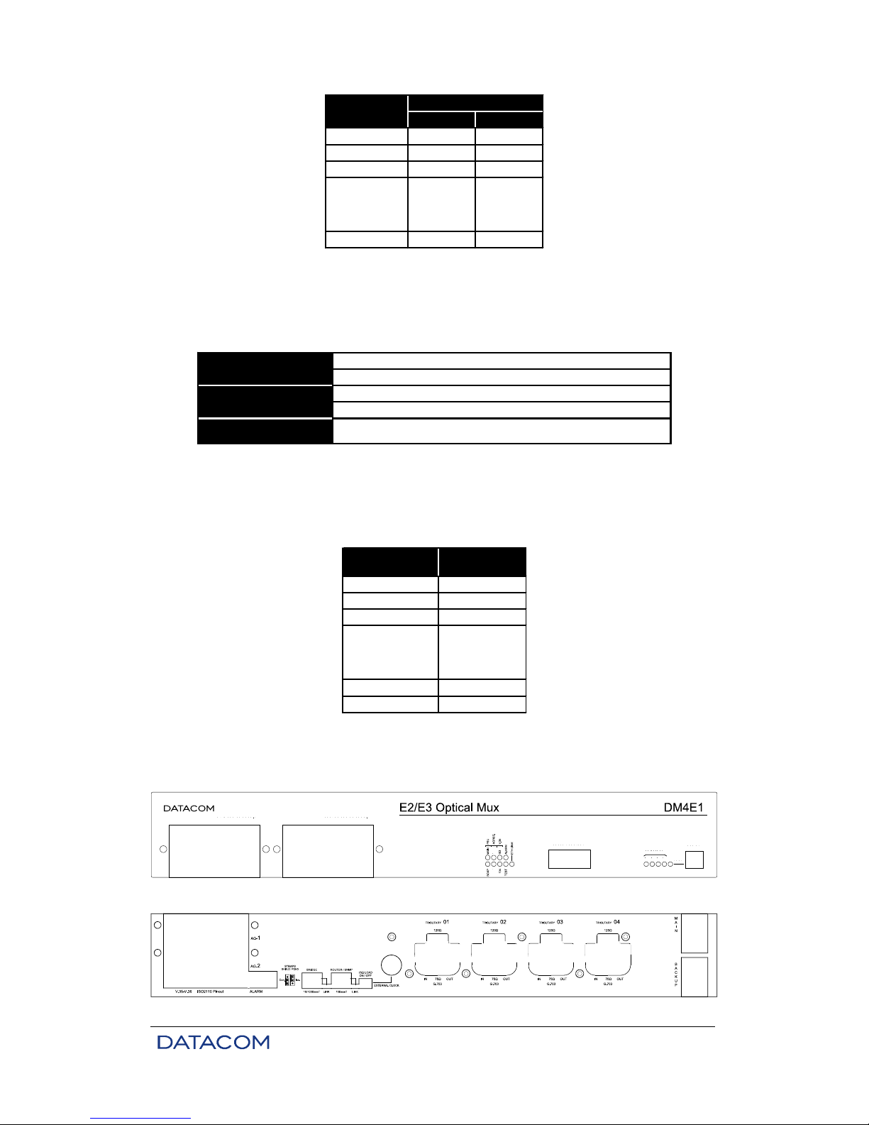
Figure 3. Front panel of the DM4E1 .............................................................. 15
Figure 4. Rear panel of the DM4E1 ............................................................... 15
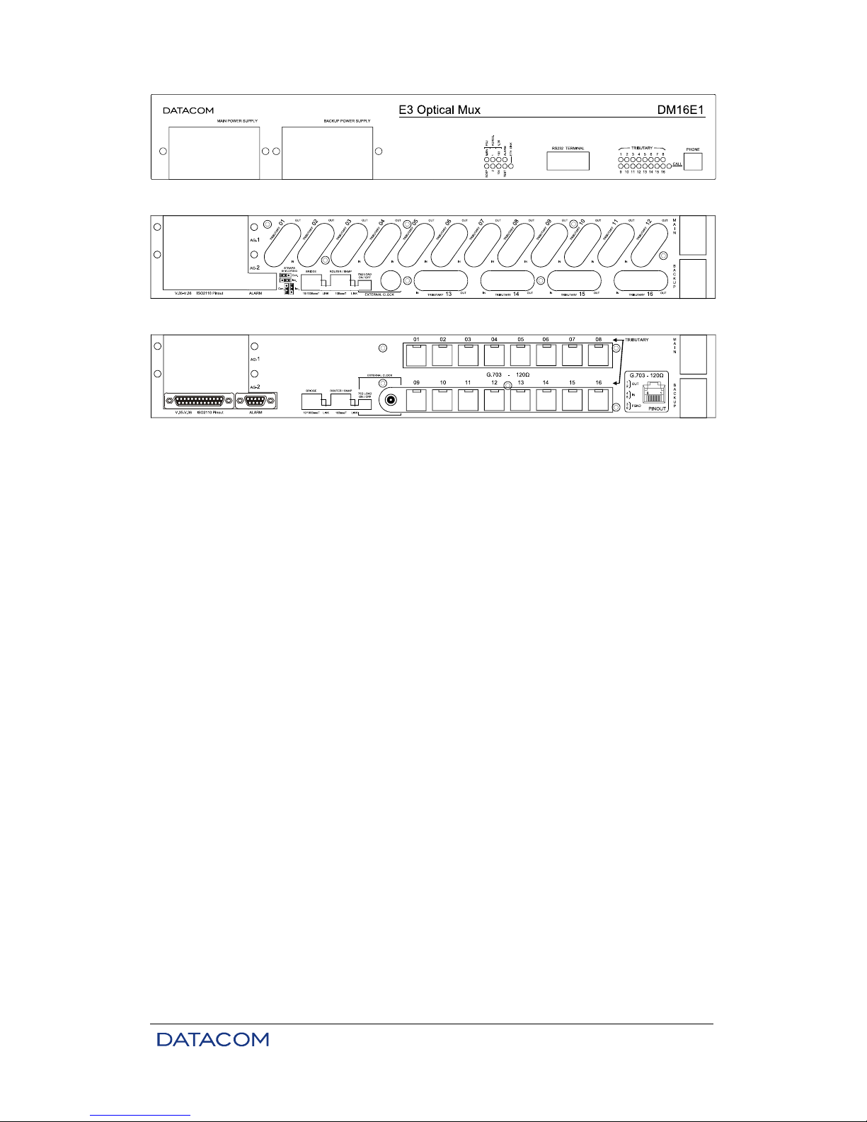
Figure 5. Front panel of the DM16E1 ............................................................ 16
Figure 6. Rear panel of the DM16E1 with either IEC or BNC connectors ...... 16
Figure 7. Rear panel of the DM16E1 with RJ45 connectors .......................... 16
Figure 8. G.703 E1 interface straps for DM4E1 ............................................. 40
Figure 9. G.703 E1 interface straps for DM16E1 ........................................... 40
Figure 10. Local analog loopback at a G.703 interface ................................... 40
Figure 11. Local digital loopback at a G.703 interface ..................................... 41
Figure 12. Example of ring topology ................................................................ 41
Figure 13. Location of V.35 / V.36/V.11 interface straps ................................. 47
Figure 14. BERT generation and reception at the digital interface .................. 48
Figure 15. Local digital loopback at the digital interface .................................. 48
Figure 16. DM16E1 panel for optic interface card ........................................... 54
Figure 17. Local analog loopback at an optic interface .................................... 54
Figure 18. Local digital loopback at an optic interface ..................................... 55
Figure 19. A DM16E1/DM4E1 loopback operating with no failures ................. 57
Figure 20. Failure in the main loopback ........................................................... 57
Figure 21. Electric E3 interface card panel ...................................................... 59
Figure 22. Local analog loopback in an electric E3 interface ........................... 61
Figure 23. Local digital loopback in electric E3 interface ................................. 61
Figure 24. Strap location ................................................................................. 61
Figure 25. Example of bridge inverse multiplexing .......................................... 65
Figure 26. Bridge card_HW1 View .................................................................. 70
Figure 27. Bridge card_HW2 View .................................................................. 70
Figure 28. Connections in Point to Point topology ........................................... 97
Figure 29. Example of bidirectional ring with Regular-Ring topology ............... 98
Figure 30. Example of bidirectional ring with Cross-Ring topology .................. 98
Figure 31. Connections in Regular-Ring topology ........................................... 99
Figure 32. Connections in Cross-Ring topology .............................................. 99
Figure 33. Example of In-Line topology ......................................................... 100
Figure 34. Connections in In-Line topology ................................................... 100
Figure 35. Example of Optic Modem topology .............................................. 101
Figure 36. Example of interface converter ..................................................... 102
Figure 37. Example of Regenerator topology ................................................ 102

TABLE INDEX
Table 1. Consumption of the basic unit and of each interface card .............. 15
Table 2. Dimensions ..................................................................................... 15
Table 3. Weight ............................................................................................ 15
Table 4. Pinout of the DM16E1/DM4E1 – PC serial connection ................... 18
Table 5. Configurable parameters using the Config Wizard Settings Menu . 25
Table 6. RJ45 connector pinout for G.703 .................................................... 38
Table 7. G.703 interface led messages ........................................................ 38
Table 8. Pinout for V.35 ................................................................................ 46
Table 9. Pinout for V.36/V.11 ....................................................................... 46
Table 10. Characteristics of optic interfaces ................................................... 53
Table 11. Optic interface led indicators (front panel) ...................................... 54
Table 12. Leds indications for electric aggregates (front panel) ..................... 60
Table 13. Pinout for RJ45 Ethernet connector ................................................ 65
Table 14. IP addresses for private networks .................................................. 73
Table 15. Valid or global IP addresses ........................................................... 73
Table 16. Pinout of the DB9 connector for alarm inputs ................................. 89
Table 17. Pinout of DB9 connector for alarm output ....................................... 89
Table 18. Alarm conditions ............................................................................. 90
Table 19. E1C straps ...................................................................................... 90
Table 20. Failure indication according to G.751 (ITU-T recommendation for E3
multiplexing) ................................................................................... 91

DM16E1 / DM4E1 Operation and Installation Manual - 204-4001-19 11
1. INTRODUCTION
DM16E1 and DM4E1 are E3, PDH (Plesiochronous Digital Hierarchy) multiplexers.
They can work with electric or optic aggregate interfaces. There are two slots for aggregate cards, which
allow for backup or ring operation.
In addition, the equipment counts on four E1 G.703 ports for tributaries in the DM4E1 model and on 16 E1
G.703 ports in the DM16E1 model. Both models have a V.35-V.36/V.11 port, an Ethernet 10BaseT port
with clearing functions, and the option to install an Ethernet Remote Bridge 10/100BaseT card.
DM16E1 and DM4E1 carry out multiplexing in accordance with G.742 (four E1 for E2 channels) and G.751
(four E2 for E3 channels) ITU-T recommendations.
In the DM16E1 model, E1 tributary interfaces can be supplied with BNC or IEC connectors for 75 ohms or
RJ45 for 120 ohms. The type of connector required should be specified when purchasing.
In the DM4E1 model, E1 tributary interfaces can be supplied with BNC or IEC connectors for 75 ohms. The
type of connector required should be specified when purchasing. RJ45 connectors for 120 ohms are
always supplied with the equipment.
A clock´s external reference is not necessary to operate the equipment. Although, a clock´s external
reference can be supplied in order to generate AIS on E1 channels.
Equipment programming can be carried out via a VT100 terminal or via a standard IBM-PC® computer,
using a VT100 terminal emulation software. The connection of the terminal to the equipment is made with
an RS-232 serial cable.
The equipment can be managed via SNMP either by the Ethernet port, on the front panel, or in band,
utilizing routing or remote management.
SNMP management is also available through the DmView application software, which runs over an HP
Open View platform. The application is able to manage a whole network, making it possible to configure,
check status, carry out tests, etc., in every network equipment.
DM16E1 and DM4E1 are physically constituted of a basic unit for mounting in 19” racks with 1,5 units of
height.
Regarding power supply, they can operate with two units of redundant power operation (Main and
Backup). The supply unit can be AC (93 to 250 V) or DC (36 to 72 V), with automatic selection. The
backup unit is identical to the main unit and is optionally supplied.
Aggregate cards and units can be inserted or removed with the equipment switched on and in operation
(hot swap).
The DM16E1 and DM4E1 equipment have a voice service channel with point-to-point, point-to-point optical
modem, regular ring, regular ring optical modem, cross ring and cross ring optical modem topologies.
There is an RJ11 connector on the front panel for a common telephonic device connection. Once the
telephone is off of the hook, an indication will be activated through sonorous alarm at the remote
equipment. The voice channel operation does not modify the data flow.
The multiplexers enable the performance of local digital and local analog loopbacks (LDL and LAL) on E1
and E3 interfaces, in addition to LDL and BERT on V.35-V.36/V.11 interfaces.
They also allow the removal and insertion of E1 signals in any point of the ring. And are provided with a
relay alarm output.

DM16E1 / DM4E1 Operation and Installation Manual - 204-4001-19 12
The interfaces can be individually configured to be part or not of the alarm equipment logic. It is possible to
configure the use of up to three external alarms in this logic. The external alarms are connected to
DM16E1/DM4E1 by a DB9 connector located at the rear panel. The external alarms can be, for example,
for ambient use (temperature and humidity) or to detect intrusion into the place where the equipment is
installed (intrusion alarm). Both types of alarm (internal or external), when activated, send monitoring
information via the management system.
DM4E1 and DM16E1 have led (light-emitting diodes) indicators on their front panels to inform the
conditions of:
• local alarm.
• active test at any interface.
• functioning/presence of power supply units.
• indication of local or remote telephone off the hook.
• status of aggregate and tributary interfaces.
1.1. Aggregate Interfaces Available
1.1.1. Aggregate Optics
There are a number of aggregate optics card options, combining the following parameters:
• Compatible with both DM16E1 and DM4E1.
• Operating on a pair of fibers or on only one (TX and RX on the same fiber).
• Laser transmission power.
• Type of connector used to connect the fiber optics.
See chapter 6 to obtain more details.
1.1.2. Electric Aggregates
• E3 interface for DM16E1 and DM4E1, operating in accordance with G.703 of 34,368 kbit/s (E3).
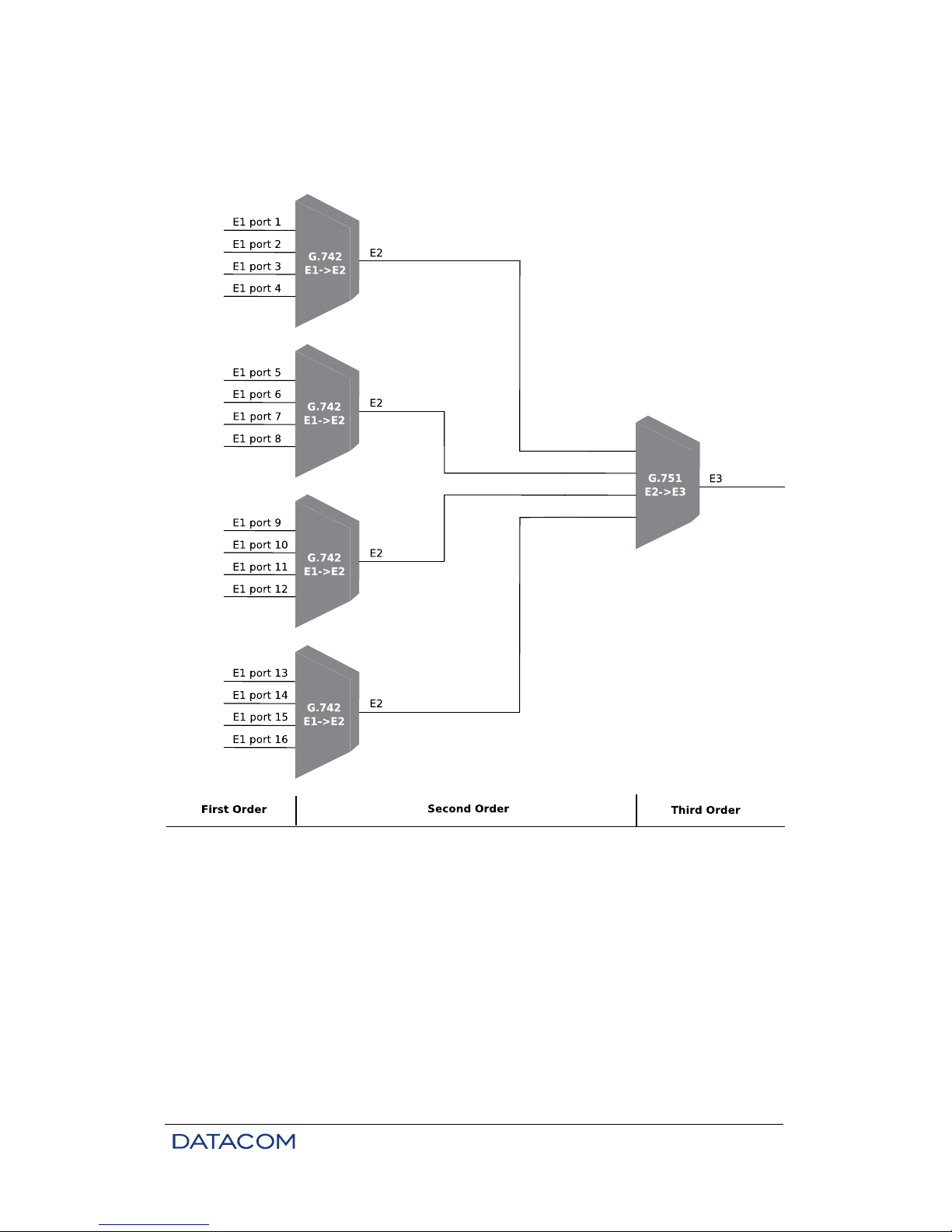
1.2. E2 and E3 Multiplexing Principle
DM4E1 and DM16E1 multiplexers are based on G.742 and G.751 recommendations.
The Multiplexing structure is represented in Figure 1:
a) G.742: 4 E1 channels, 2048kbit/s (first order) are multiplexed generating an E2 channel, of
8448kbit/s (second order);
b) G.751: 4 E2 channels are multiplexed generating an E3 channel, of 34.368kbit/s (third order).
It should be observed that it is possible to form E2 channels with first order tributaries containing or not the
G.704 frame structure, provided the rate is 2048kbit/s. Similarly, an E3 channel can be formed by channels
with a frame structure compatible or not with that of G.742, provided the rate is 8448kbit/s.
An interesting thing about PDH multiplexing is the possibility of using different clocks, in terms of phase
and frequency, at each input point. Eventual differences are automatically compensated by the equipment.
However, the clocks must be within the standards established for G.703:
• 2048kHz ± 50 ppm (parts per million);
• 8448kHz ± 30 ppm;
• 34368kHz ± 20 ppm.
The clocks generated internally by DM16E1 and DM4E1 are within the tolerances above.
DM16E1 / DM4E1 Operation and Installation Manual - 204-4001-19 13
In the two multiplexing categories, drop-insert can be configured for tributary channels, so that several
DM4E1 or DM16E1 units can share the same E3 link. Each unit inserts data into channels which are not
used by the others, and this way form an optic ring with 100% utilization of the link. More details can be
found in chapter 15.
Figure 1. PDH hierarchy
1.3. Ethernet Remote Bridge
The equipment can be supplied with an Ethernet Remote Bridge interface card, which implements a
10/100BaseT port via an RJ45 connector located on the rear panel. The connector and led indicators are
always assembled independently from the card itself, and can be added later.
More details about this interface in chapter 8.
DM16E1 / DM4E1 Operation and Installation Manual - 204-4001-19 14
2. TECHNICAL SPECIFICATIONS
2.1. Environmental Conditions
Operational temperatures: 0 to 60°C.
Relative humidity: up to 95% uncondensed.
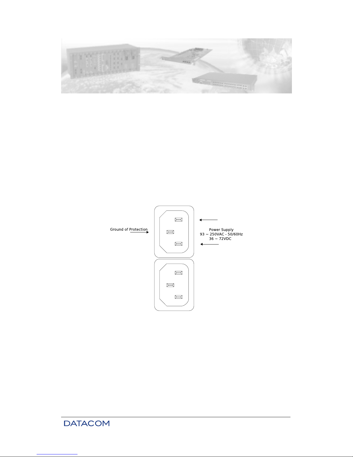
2.2. Supply Unit
The supply of energy to the equipment is made through a tripolar cable (IEC-320 standard). When using
DC voltage, the cable must be cut near the AC connection plug and connected in such a way that the
central pin of the plug corresponds to the frame ground connection and the other two pins correspond to
power units. Polarity is not important, as shown in Figure 2, below. The body of the equipment is
connected directly to the frame ground.
The equipment can be connected to any voltage within the ranges specified below, without any kind of
manual selection. This is automatically done by the equipment, for both the main and backup units. The
backup unit is optional.
Figure 2. Power supply input panel
2.3. Consumption
To estimate the total consumption of the equipment, add the consumption of the basic unit to the
consumption of the aggregate interfaces used.
DM16E1 / DM4E1 Operation and Installation Manual - 204-4001-19 15
DC AC
DM4E1 11,00 9,00
DM16E1 12,00 9,81
E3 optic 1,80 1,50
Bridge 1,50 1,23
Power (W)
Interface
1,10 0,90
E3 electric
- Aggregate
- Tributary
Table 1. Consumption of the basic unit and of each interface card
2.4. Dimensions
The equipment is mounted in a 19” rack with a height of 1.5 U.
Height
Width
Depth
65mm without rubber base supports
72mm with rubber base supports
435mm without subrack brackets
483mm with subrack brackets
232mm
Table 2. Dimensions
2.5. Weight
Table 3 shows the weights of DM16E1, DM4E1 and respective modules:
DM4E1 3,10
DM16E1 3,40
E3 optic 0,10
Bridge 0,10
Power Supply 0,18
Interface
0,14
E3 electric
- Aggregate
- Tributary
Weight (kg)
Table 3. Weight
2.6. Front and Rear Panels
Figure 3. Front panel of the DM4E1
Figure 4. Rear panel of the DM4E1
DM16E1 / DM4E1 Operation and Installation Manual - 204-4001-19 16
Figure 5. Front panel of the DM16E1
Figure 6. Rear panel of the DM16E1 with either IEC or BNC connectors
Figure 7. Rear panel of the DM16E1 with RJ45 connectors
2.7. Led Indicators
PSU (MAIN and BACKUP): indicate the status of the power unit supplies. When lit, it signals that the
supply is operating normally; when unlit, it shows that there is no unit; when flashing, it indicates a
defective unit, or one which is disconnected from the electric network.
AGGREG (1 and 2): indicates the status of the aggregate interface. Unlit shows that no interface is
present; continually lit shows a synchronized interface; flashing indicates LOS or AIS. More details in item
6.3.
TRIBUTARY (1 to 16 in DM16E1 and 1 to 4 in DM4E1): indicates the status of the equipment E1 G.703
tributaries. The behavior pattern is similar to that of aggregate led indicators. More details in item 4.2.
V.35 (103 and 104): reflects the status of 103 and 104 signals at the V.35 tributary.
ALARM: indicates simultaneously alarms of high and low priority. This indication will remain on until the
alarm is eliminated and the user initiates a command of recognition through the terminal port or via the
DmView SNMP management software. More details in chapter 12.
TEST: indicates that the equipment is undergoing a test. It will remain lit while any interface is executing a
test.
ETH LINK: indicates the presence of a signal at the Ethernet port on the rear panel of the equipment.
CALL: lights up when the service channel telephone is off of the hook; flashes when the equipment
receives a call from the remote equipment.
2.8. Equipment Interfaces
TERMINAL: port RS232 (V.24/V.28) in DB9 female connector, utilized to connect the equipment to the
configuration terminal by means of a serial cable. The pinout description of this connector can be seen in
chapter 15.
PHONE: connection of a fixed telephone with an RJ11 connector using a service channel. Used for
communication between operators during installation and maintenance of the link.
AGGREGATES (AG1 and AG2): two slots for the insertion of aggregate interfaces, either optic or electric.

DM16E1 / DM4E1 Operation and Installation Manual - 204-4001-19 17
V.35-V.36/V.11: DB25 connector with ISO2110 Amd.1 pinout for connection to the V.11 interface at
2048kbit/s, which can be configured to assume the position of any E1 tributary within channels E2 or E3.
More details in chapter 5.
ALARM – IN and OUT: in one DB9 female connector, enables the relay contacts of the alarm, and serves
as an input for external alarms coming from other equipment. To see a description of pinout, consult
chapter 12.
10/100Base-T-Bridge: RJ45 connector for Ethernet Remote Bridge. More details in chapter 8. By this
connector there is a led indicator which shows the establishment of a link. The connectors and the led are
always assembled independently from the bridge card, which is optional.
10BaseT-SNMP: RJ45 connector for the connection of Ethernet network to SNMP management, using the
DmView software. A led indicates the status of the link.
EXTERNAL CLOCK: this BNC (or IEC169/13) connector can be connected to an external clock source of
2048kHz (in accordance with G.703), for use with E1 interfaces.
MAIN and BACKUP: ports for DC or AC voltage, as described in chapter 2.2.
TRIBUTARY (1 to 16 in DM16E1): the equipment can be supplied with RJ45 connectors for an impedance
of 120 ohms, or with BNC or IEC169/13 connectors for 75 ohms. In this case, there are straps for the
connection of the coaxial cable external shield to the frame ground (grounding).
TRIBUTARY (1 to 4 in DM4E1): the equipment can be supplied with BNC or IEC169/13 connectors for 75
ohms. In addition, RJ45 connectors for an impedance of 120 ohms are always present. In the case of 75ohm connections, straps are available for the connection of the coaxial cable external shield to the frame
ground (grounding).
2.9. Applicable Norms
ITU-TS: G.651, G.652, G.703, G.742, G.751, G.821, G.823, G.826, G.955, V.11.
Ethernet: IEEE 802.3.
Bridge: IEEE 802.1, 802.1Q Tag-based VLANs, 802.1Q VLAN priority Tag e Port Based VLAN.

DM16E1 / DM4E1 Operation and Installation Manual - 204-4001-19 18
3. MANAGEMENT VIA THE TERMINAL PORT
DM4E1 and DM16E1 can be configured in two ways: via SNMP (DmView software) or via a VT100
Terminal or emulator.
This chapter addresses management via a Terminal port. For information with respect to management via
DmView, please consult the user’s guide that accompanies the DmView application software.
3.1. PC or Terminal Connection
The DM16E1/DM4E1 cards have a DB9 female connector on their front panel for the connection of the
equipment to a PC or Terminal, by means of a cable with a DB9 male connector at the end of the
DM16E1/DM4E1 and a female DB9 or DB25 connector on the end of the PC. The pinout is presented in
the table below:
DB9 (DM16E1/DM4E1 DB9 (PC) DB25 (PC)
pin 2 pin 2 pin 3
pin 3 pin 3 pin 2
pin 5 pin 5 pin 7
Table 4. Pinout of the DM16E1/DM4E1 – PC serial connection
To be sure that this will not happen, measure the voltage between these pins using an AC voltmeter. If a
potency difference is detected, check to see whether the DM16E1/DM4E1 and the PC are duly grounded
and then interconnect the signal ground to the DM16E1/DM4E1 frame ground (see item 10.1). This should
solve the problem. After taking these steps, measure the AC voltage again before connecting the serial
cable.
3.2. Introduction
Management via a Terminal port permits:
• Remotely:
− To configure all equipment interfaces.
− To activate tests on interfaces.
− To check the status of interfaces.
• Locally only:
− To configure SNMP parameters and the equipment network.
− To reconfigure the terminal access password.
− To restart the equipment.
For remote equipment management, it is necessary to connect them to the local equipment via an
aggregate link.
Take care so that there is no difference in potency between pin 5 of DB9 at DM16E1/DM4E1 (signal
ground) and pin 5 of DB9 (or pin 7 of DB25) at the PC/Terminal. If this happens, the serial interfaces of the
equipment and of the PC/Terminal will be damaged.

DM16E1 / DM4E1 Operation and Installation Manual - 204-4001-19 19
3.3. Configurations for Management via the Terminal Port
Always use this system when new equipment is inserted into the ring or in cases when it is necessary to
alter the topology of the operation. For more information about how to connect the serial cable, consult
chapter 3.
Changes in the operation topology may cause the loss of data during configuration since it involves
changes in the interface data flow. New topology configurations may also momentarily or permanently
disconnect the management of ring configurations.
The insertion of new ring topology equipment only causes the loss of data during the physical insertion of
the equipment. Then the backup option is active, the removal of equipment is seen as a failure, and the
loss of data is only momentary. If the equipment has been configured correctly, management should
function normally.
The below described configurations should be made locally (direct connection through the equipment
Terminal port) before field installation:
• All the equipment must be functioning with the same topology configurations. Different topology
configurations alter the normal flow of data, which makes management impossible.
• Correct configuration of MAIN / BACKUP aggregate cards. Errors in this configuration can cause
the isolation of equipment in the ring, or loss of the management link. It is recommended not to
alter factory values for these parameters (MAIN card in slot AG1 and BACKUP card in slot AG2).
• Tests should be deactivated in all aggregates. Test activation in remote aggregates causes the
equipment to ignore management information. Aggregate tests can only be deactivated locally.
3.4. Configurations of the Terminal Serial Interface
The terminal must be configured for 9600bit/s, without flow control, 1 stop bit and without parity bit. When
configuration is done with Windows 2000, it is recommended not to use the HyperTerminal, as it
presents some functional problems on this platform. Therefore, the use of Tera Term Pro, a freeware
software, is recommended. It can be downloaded at the following electronic address:
http://www.vector.co.jp/authors/VA002416/teraterm.html
If possible, the option to send characters automatically (without pressing ENTER) should be selected in the
emulation software.
The Terminal authentication screen is represented below:
# ------------------------------------------------------------------------# DataCom Telematica – DM16E1 Multiplexer
#
# ------------------------------------------------------------------------#
#
#
#
# Password: [ ]
#
#
#
#
#
#
#
#
#
#
#
#

DM16E1 / DM4E1 Operation and Installation Manual - 204-4001-19 20
3.5. Trial Operation
Trial equipment may have a limited operational period. The header on the terminal screen indicates the
time remaining for use, in accordance with screen below:
# ------------------------------------------------------------------------# DataCom Telematica – DM16E1 Multiplexer
# Trial time left:1 Days
# ------------------------------------------------------------------------#
#
#
#
# Password: [ ]
#
#
#
#
#
#
#
#
#
#
#
#
#
#
The trial period can be finalized either by the terminal or via management. On the terminal, this is done by
entering a specific password, which can be obtained from DATACOM.
The trial finalization password can be used in two ways via the Terminal:
• Remotely: the password is inserted after having selected the equipment to be configured (see
chapter 3.7). The insertion of the password removes the equipment from trial automatically.
• Locally, on the authentication screen of the terminal: when inserting the specific equipment
password (same password for local or remote equipment), the screen presented below is
displayed:
On the authentication screen, the software requests the equipment access password. The default
password is "proxySNMP
". To obtain further information on how to disable or reconfigure the password,
see chapter 3.6.
If the password is lost, contact our Technical Support team to solve the problem, informing the MAC
number of the equipment and the serial number. In order to know the MAC number, please access the
terminal authentication screen and type “l” (lowercase L).

DM16E1 / DM4E1 Operation and Installation Manual - 204-4001-19 21
# ------------------------------------------------------------------------# DataCom Telematica – DM16E1 Multiplexer
#
# ------------------------------------------------------------------------# Trial Time Configuration
#
#
# Trial Code Entry : [ ]
# Enter new trial time or [F]inish trial
#
#
#
#
#
#
#
#
#
#
#
# ------------------------------------------------------------------------# <ENTER> Return and Save <ESC> Return without Saving
# -------------------------------------------------------------------------
The trial is finalized by typing “F” and <ENTER> on this screen.
3.6. Main Terminal Screen
Once the Terminal has been authenticated, it will operate with a timeout of 10 minutes, valid for any of the
subsequent screens. Once this time is up, the terminal will revert to the authentication screen, and all
configurations not saved in the equipment will be lost.
# ------------------------------------------------------------------------# DataCom Telematica – DM16E1 Multiplexer
#
# ------------------------------------------------------------------------#
#
# 1 - Choose Equipment to Configure
#
# 3 - SNMP Parameters
# 4 - Terminal Password Configuration
# 5 - Firmware download to local Equipment
#
# E - Exit
# R - Exit and Reset
#
#
#
#
#
# Option: [ ]
# ------------------------------------------------------------------------#
# -------------------------------------------------------------------------
Main menu options:
• Choose Equipment to Configure: Selection of the equipment to be managed, with a choice
between local and some remote locations. This option is detailed in chapter 3.7.
• SNMP Parameters: Permits the configuration of parameters for basic SNMP operations. To
obtain more details about these options, see chapter 13.
− Direct IP SNMP management: Select the type of management (e.g., SNMP). In order to
set management via a serial port, this parameter should be disabled.
Trial equipment indicate the remaining operational time on the screen header. If the time expires, the
equipment will be restarted and will not transmit data anymore.

DM16E1 / DM4E1 Operation and Installation Manual - 204-4001-19 22
− Manager IP address to send traps: The addresses of the management workstations
(using DmView) that are present in the sub-network must receive updates on changes in
the interfaces installed in the equipment. Factory value: 0.0.0.0. To avoid unnecessary
LAN traffic, only configure this parameter if SNMP management is going to be used.
− Read SNMP Community: Keyword that must be included in SNMP packs for reading
permission. Factory value: public.
− Read and Write SNMP Community: Keyword that must be included in SNMP packs for
writing permission. Factory value: private.
− Allow SNMP SET operations: Allows to activate/deactivate modifications of parameters
in the equipment via SNMP. This protection has no effect on configurations done via the
Terminal port.
• Terminal Password Configuration: Permits the access password to be altered and/or disabled.
− Ask for Password on Terminal initialization: Enables/disables the terminal access
password. If the password is disabled and then enabled again, the terminal reverts to the
factory value: "proxySNMP". Factory value: YES.
− Change Password: Permits the terminal access password to be modified.
• Firmware Download to Local Equipment:
Enables the firmware updating via the terminal.
For further efficiency, the update through TFTO is recommended (refer to 14.2 item).
• Exit / Exit and Reset: Presents options to close configurations via the Terminal port, reverting to
the terminal authentication screen. In order to assure that the parameters, which are dependent
on reinitiating the equipment, take effect, it is necessary to use the "Exit and Reset" option. The
terminal will prompt the use of this option whenever necessary.
3.7. Option Choose Equipment to Configure
This option opens the equipment choice menu.
On this screen it is possible to choose the equipment to be configured: local equipment or remote
connected to the local one through an aggregate link.
In order for the management system to function correctly, configurations must initially be made locally. This
requirement is necessary because an established aggregate link is needed for the management operation.
Details about the required configuration are addressed in chapter 3.3.

DM16E1 / DM4E1 Operation and Installation Manual - 204-4001-19 23
# ------------------------------------------------------------------------# DataCom Telematica – DM16E1 Multiplexer
#
# ------------------------------------------------------------------------# Choose Equipment
#
# *1 - DM4E1 Multiplexer local
# *2 - DM4E1 Multiplexer 244391
#
#
#
#
#
#
#
#
#
#
#
# Option: [ ]
# ------------------------------------------------------------------------# <ENTER> Refresh <ESC> Exit
# -------------------------------------------------------------------------
Option 1 always refers to local equipment (with which the Terminal port is connected). The remaining
options refer to remote equipment connected via the aggregate link.
Remote devices are listed in accordance with their serial numbers.
Some remote devices may not be available for management from this terminal. This is due, in general, to
the fact that there is local management available for this equipment, via a Terminal or via DmView.
Another possible reason is that the management link is not established yet. The equipment available for
management is marked with the indicator "*".
If the equipment on trial is chosen, then the password for ending the trial period is automatically lost. If the
user keys in <ENTER>, the equipment will continue to be used on trial.
Once an equipment is chosen (options 1 to 2 in the example), configuration can start, either locally or
remotely.
In order to update equipment management properties, use the "Refresh" option, activated by <ENTER>.
To return to the main screen of the Terminal, use the "Exit" option, activated by <ESC>. Following the
terminal standard, the main functions are detailed on the status bar (last line on the screen, between the
separators formed by "-").
Once the equipment to be configured has been chosen, the terminal will exhibit information on
configuration and status referring to these specific units. In the following sub-sections, details of the
configuration of the equipment interfaces will be addressed.
When
the trial period is over, the equipment is restarted and does not transmit data anymore. Equipment
with the trial time expired only restart working after the typing of the password.

DM16E1 / DM4E1 Operation and Installation Manual - 204-4001-19 24
3.8. Equipment Main Menu
# ------------------------------------------------------------------------# DataCom Telematica – DM16E1 Multiplexer
# /local
# ------------------------------------------------------------------------# Main Menu
#
# 1 - Settings Menu
# 2 - Tests Menu
# 3 - Status Menu
# 4 - View System Parameters
# 5 - Network Parameters
# 6 - Config Wizard
#
#
#
#
#
#
#
# Option: [ ]
# ------------------------------------------------------------------------# <ESC> Return to Previous Menu
# -------------------------------------------------------------------------
According to the equipment chosen, the terminal header will be slightly altered with the inclusion of
location data in the terminal menu tree. This system is similar to a directory structure.
The first level of the directory tree identifies the equipment being configured. Lower levels refer to menus
chosen from the main menu. In this manual, menus will be referred to according to this designation (if any);
the equipment identifier will be omitted.
Main Menu options (and respective chapters):
• Settings Menu: Allows enabling and configuration of data interface parameters, test activation and
alarm generation.
• Tests Menu: Enables tests in the data interface. Test activation in remote devices may disconnect
the management system. See chapter 3.3 for more information.
• Status Menu: Verifies the status of equipment interfaces. Also allows restarting the alarm status.
• View System Parameters: This menu shows general features of the equipment. It sets the
equipment number within the ring (device identifier), which is essential for the management to run
correctly. See chapter 3.3 for more information.
• Network Parameters: This menu sets the parameters for IP interfaces (Ethernet and routing).
• Config Wizard: Configuration menu for quick installation.
3.9. Config Wizard
The Config Wizard menu allows fast access to the routing interfaces, being ideal to quickly configure IPbased management systems. The illustration below shows the Config Wizard main screen:

DM16E1 / DM4E1 Operation and Installation Manual - 204-4001-19 25
# --------------------------------------------------------------------------# DataCom Telematica - DM16E1 Multiplexer
# /local/wizard
# --------------------------------------------------------------------------# Topology : [ Point to Point ]
# Read SNMP Community : [public ]
# Read and Write SNMP Community : [private ]
# Trap1:[ 0. 0. 0. 0] Trap2:[ 0. 0. 0. 0] Trap3:[ 0. 0. 0. 0]
#
# WAN1 DMLAN Rate:[ In Band 40k ] Tributary:[ 1]
# WAN2 Protocol: [ PPP ] Tributary:[ 1] Clk:[ Int. ] Dir:[ V.35 ]
#
# Gateway Interface DLCI Host Address
# [ Ethernet ] [0000] [ 0. 0. 0. 0]
# RIP
# Interface Enable DLCI Sub-Net Address Sub-Net Mask TX _ RX
# Ethernet [ YES ] [192.168. 0. 25][255.255.255. 0] [ RIP1_Both ]
# WAN1(DMLAN) [ YES ] [192.168. 50. 50][255.255.255. 0] [ RIP1_Both ]
# WAN2 [ NO ][0000] [192.168. 2. 25][255.255.255. 0] [ RIP1_Both ]
#
# --------------------------------------------------------------------------# <ENTER> Return and Save <ESC> Return without Saving
# ---------------------------------------------------------------------------
SNMP management will not operate during setup when using the Config Wizard. This also happens when
the device is managed via terminal.
All changes done in the Config Wizard screen are automatically activated and saved on E2PROM when
pressing <ENTER>.
Changes to the gateway default configuration will generate a reset on the respective equipment.
Configurable parameters are shown in table below:
Parameter
Topology
Read
Community
Write
Community
TrapN
Interface
DLCI
Host address
Tributary
Clk
Direction
Enable
DLCI
Sub-Net
Address
Sub-Net Mask
Base address for structured sub-net
address on the interface
Sub-net IP mask on the interface
Description
Equipment
Operating topology
DLCI used by the interface. Valid only for
WAN2 using Frame Relay
SNMP read community
SNMP write community
Target address for traps
Gateway
Interface where the gateway default is
connected
Defines DLCI for gateway when using
Frame Relay interfaces.
Gateway default address
Roteamento
Indicates the E1 tributary used by WANs.
Does not apply to WAN1 configured to
40k In Band
Clock reference used by WAN2
Data direction for the WAN2 interface
Interface enabling
Table 5. Configurable parameters using the Config Wizard Settings Menu

DM16E1 / DM4E1 Operation and Installation Manual - 204-4001-19 26
3.10. Settings Menu
This menu is used to grant access to equipment settings (options 1, 2, and 3) and to the management of
user settings (options 4 to 9).
Submenus of the Settings menu:
• General Settings: Parameters that affect the equipment as a whole. Allows changes to the
topology, scrambler, external clock settings, backup settings and enabling of external alarm.
• Port Settings: Individual parameters for modular interfaces (aggregate or bridge) or for interfaces
mounted in the equipment.
• Aggregate Map Settings: This table indicates where each of the enabled tributaries will be
directed to
# ------------------------------------------------------------------------# DataCom Telematica – DM16E1 Multiplexer
# /local/settings
# ------------------------------------------------------------------------# Settings Menu
#
# 1 - General Settings
# 2 - Port Settings
# 3 - Aggregate Map Settings
#
# 4 - Check user settings
# 5 - Update changes (user memory to equipment)
# 6 - Recall equipment configuration (equipment to user memory)
# 7 - Save equipment configuration to E2PROM
# 8 - Recall E2PROM settings to user memory
# 9 - Recall Factory values to user memory
#
# User memory status :[ E2PROM Config. ]
#
# Option: [ ]
# ------------------------------------------------------------------------# <ENTER> Refresh <ESC> Exit
# -------------------------------------------------------------------------
Equipment configurations are stored in non-volatile memory (E2PROM). This feature guarantees that
settings will not be lost in case of a power failure or system reset (as during software upgrade).
The following steps are necessary to change E2PROM settings:
a) Load current settings from memory.
b) Change settings.
c) Test the new settings without applying them (optional).
d) Apply the new settings on the equipment (volatile memory).
e) Save the settings in non-volatile memory (E2PROM).
These steps are necessary because many settings are dependent on each other. For example, in DM16E1
devices, the V.35 tributary interface uses the same physical space within the E3 frame as tributary E1
number 16. Therefore, in a DM16E1 device with an active tributary 16, a command to activate the V.35
tributary interface could be considered inconsistent.
The mechanics described above allow for temporary inconsistencies (step b), as in the example of
simultaneous activation of tributary 16 and tributary V.35. Inconsistencies are corrected in a draft copy of
the equipment memory (user memory). Optionally, the equipment may validate the new configuration (step
c). This checking step has the purpose of being a guide in the configuration validation. Another advantage
is that the equipment may continue to operate normally during the reconfiguration process.
Next, the configuration should be validated. By security, the equipment uses a volatile memory (equipment
memory) as base for the equipment using. Thus, coherent configurations can be tested as for
functionalities with the possibility of an easier return to a functional configuration hosted on a non-volatilememory (E2prom settings). Once the configurations are validated, the equipment modifies its operation
mode and data loss may occur.

DM16E1 / DM4E1 Operation and Installation Manual - 204-4001-19 27
Finally, if the desired result was achieved using the new configurations, they can be stored in non-volatile
memory (step e). Values saved in this memory are also accessible to users anytime for the establishment
of new configurations. Additionally, factory values can also be used to the same purpose.
Memory functions of the Settings menu are described below:
• Check user settings. Validates user memory configuration.
• Update changes (user memory to equipment): Tries to apply user memory to equipment.
• Recall equipment configuration (equipment to user memory): Copies equipment memory
configuration to user memory.
• Save equipment configuration to E2prom: Stores resident equipment memory into non-volatile
memory (E2PROM settings) inside the equipment.
• Recall E2prom settings to user memory: Copies settings from non-volatile memory (E2PROM
settings) inside the equipment to user memory.
• Recall Factory values to user memory: Loads preset factory values to user memory.
Responses to the commands presented above are directed to the User memory status field described
below:
• User memory status: Displays the status of user memory and the results of setup operations
(options 3 to 8 of the Settings menu). All possibilities for this field are described below:
− Factory Config.: Indicates that the equipment is operating under factory preset settings,
normally in response to a request to recall factory values (see item Recall Factory values
to user memory in this chapter).
− E2prom Config.: Indicates that the equipment is operating on non-volatile memory
(E2PROM) settings. This is the standard response when the equipment is restarted and
when a request is made to store active memory contents (equipment configuration) on
E2PROM memory.
− Temporary Config.: Indicates that the user memory is not identical to the equipment
memory. This occurs in response to changes made to the user memory that are not
activated yet.
− Temp. Full Compatible Config.: Indicates that the user memory is fully consistent and
may be activated on the equipment. Please note that even a fully consistent memory
does not guarantee a correct configuration. As such, memory activation may cause
incorrect results. This status is a response to a user memory verification request (see
Check User Settings in this chapter).
− Temp. Partial Compatible Config.: Indicates that the user memory is partially
inconsistent, but the inconsistency was overridden by the equipment (e.g. by
deactivating an interface). Therefore, this configuration may be activated. This may
cause the equipment to behave slightly differently from the settings intended, in
response to a user memory verification request (see Check User Settings in this
chapter).
− Temp. Invalid Config.: Indicates that the user memory is inconsistent and needs to be
corrected. Any attempt to activate this configuration will have no effect on the equipment.
This status is a response to a user memory verification request (see Check User
Settings in this chapter).
− Full Active Config.: Indicates that the user memory was successfully transferred to the
active equipment memory. Please note that even a fully consistent memory does not
guarantee a correct configuration for a given user application. This status is a response
to a user memory verification request. See Update changes (user memory to equipment)
in this chapter.

DM16E1 / DM4E1 Operation and Installation Manual - 204-4001-19 28
− Partial Active Config.: Indicates that the user memory was partially transferred to the
active equipment memory due to some inconsistency. To check which settings were
changed, use the Recall equipment configuration (equipment to user memory) option
previously described in this chapter. This status is a response to a user memory
verification request. See Update changes (user memory to equipment) in this chapter.
− Invalid Config.: Indicates that the user memory was not accepted by the equipment due
to inconsistencies. At this point, it is possible to retrieve a consistent configuration (see
instructions on how to retrieve previous settings above). Alternatively, a correction of the
inconsistency may be attempted. This status is a response to a user memory verification
request. See Update changes (user memory to equipment) in this chapter.
Finally, good configuration practices include step-by-step changes to the user memory with frequent tests.
See Update changes (user memory to equipment) in this chapter to obtain more information. Thus,
isolating possible configuration inconsistencies becomes a simpler task.
3.10.1. General Settings
# ------------------------------------------------------------------------# DataCom Telematica – DM16E1 Multiplexer
# /local/settings/equip
# ------------------------------------------------------------------------# General Settings
#
# Topology :[ Point to Point ]
# ALS Protection Retry Time :[ 10 seconds ]
# 2048kHz E1 AIS Reference :[ Internal ]
# Aggregate Backup :[ Automatic ]
# Backup Enter Time :[ Instantaneous ]
# Backup Return Time :[ 30 seconds ]
# External Alarm 1 :[ Disable ]
# External Alarm 2 :[ Disable ]
# External Alarm 3 :[ Disable ]
# Alarm Output Activity Time :[ Forever ]
# Alarm Output Frequency :[ Infinity ]
#
#
#
# ------------------------------------------------------------------------# <ENTER> Save and Exit <ESC> Exit <SPACE/TAB> Change
# -------------------------------------------------------------------------
• Function keys:
− Arrows: Alternate among the options on the screen.
− Enter: Saves settings on user memory and exits screen.
− Esc: Discards changes and exits screen.
− Tab / Spacebar: Changes the value of each configuration field. The Tab key shows the
next option while the spacebar shows the previous option, making selection from long
lists of options easier.
Menu options:
• Topology. Operating topology for the equipment. This configuration is dependent on the
aggregate cards installed. Additional information may be found in chapter and in chapter 15. In case of
inconsistencies on this setting, the device will retrieve the factory default option (Point to Point). The
equipment may operate under the following topologies:
− Interface Converter: Data received from the main aggregate card are transmitted directly
to the backup interface and vice-versa. A proprietary scrambler is inserted in the optic
aggregates to assure clock regeneration.

DM16E1 / DM4E1 Operation and Installation Manual - 204-4001-19 29
− Transparent Interface Converter: Similar to Interface Converter but does not use a
scrambler in the optic aggregates. For this configuration to work properly, it is necessary
to ensure that the device connected to the optic side is transmitting data with adequate
variability to clock regeneration.
− Regenerator: Identical to the Transparent Interface Converter. The equipment is only
used to regenerate optic signals.
− Point to Point: Two devices are connected in a point to point topology. The chosen
tributaries are inserted in the upper order hierarchies (E2 and E3) in one end and
removed from the other one in both transmission directions. This topology allows the use
of a backup card for additional protection.
− Regular Ring: Two or more devices are connected in a ring topology. The chosen
tributaries are inserted in the upper order hierarchies (E2 and E3) in one end and
removed from the selected devices, which may be any of the components of the ring.
The main aggregates configure one ring, and the backup aggregates configure a
protection ring to be used if the main link is lost. One or two cards per equipment may be
used. Two cards are required in backup configurations. In this topology, since data
pertinent to the main link come from one location and are redirected to another one, the
use of bidirectional aggregate cards is considered inconsistent. This configuration is
suitable to three or more devices. It should not be used in a two-device setup.
− Cross Ring: Two or more equipment are connected in a ring topology. The chosen
tributaries are inserted in the upper order hierarchies (E2 and E3) in one end and
removed from the selected devices, which may be any of the components of the ring.
Here the pair formed by the RX of the main card and by the TX of the backup card
configures the main data link. Similarly, the pair formed by the TX of the main card and
by the RX of the backup card configures the protection data link. The main advantage of
this topology is the possibility of using bidirectional cards, hence using only one fiber link
(instead of two) between two adjacent points in the ring. As two cards are needed to
implement this configuration, the use of backup is native.
− Line Terminator / Line Network: In-line configuration. It works similarly to the Cross Ring
topology, except for the fact that the ring ends are not interconnected. This configuration
does not allow backups. The end devices must be configured as Line Terminators, while
the remaining ones must be set to Line Network.
− Transp. Opt.Modem / PtP Opt.Modem: Under these topologies, data received from the
aggregates are directed to an E3 tributary (DM4E1 E3 mode, and DM16E1). These may
use backups as in Point to Point topologies. Using Transp. Opt.Modem, data are
forwarded directly, with no modifications. PtP Opt.Modem allows remote device
management. The equipment will not allow these topologies when the E3 internal
tributary is not present (invalid configuration).
− Regular Ring Opt.Modem / Cross Ring Opt.Modem: Similarly to Transp. Opt.Modem,
these topologies allow E2/E3 as tributaries in a Regular Ring or Cross Ring. As such,
access from remote locations to the data in this ring is allowed. The E2/E3 used must be
structured containing E1 tributaries according to the PDH hierarchy. All E1 channels not
used in the remote location must stay in pass-through so as to guarantee the correct
functioning of the devices connected to the ring. This configuration is suitable to three or
more devices. It should not be used in a two-device setup.
• ALS Protection Time: Automatic Laser Shutdown control. This feature corresponds to the period
during which the laser is turned off whenever LOS is detected on the protected interface (RX in the
opposite direction, same aggregate interface except on Regular Ring and Regular Ring Opt.Modem
topologies).This protection affects only optic interfaces that are installed in the equipment. Electric
interfaces are always on. In order to disable this protection, use the value Always on.When this protection
is active, the Backup return time must be set to at least 10 seconds.

DM16E1 / DM4E1 Operation and Installation Manual - 204-4001-19 30
• 2048kHz E1 AIS Reference: Used in the event of data loss in an aggregate link. This loss must
be signaled to the tributaries according to the G.742/G.751 recommendations. It is possible to set
which clock reference will be used to emit AIS to the tributaries when this condition occurs.
Options are:
− Internal: Uses the local clock reference.
− External: Uses the external clock reference, which is accessible on the rear panel of the
device. If this clock fails, the equipment will automatically switch to the internal clock
reference.
• Aggregate Backup: Used as backup to the equipment. In the descriptions that follow, the
aggregate interface set up as MAIN is referred to as the main link. The same applies to the
backup interface. Options are:
− Disable: Backup is disabled, and use of the main link is mandatory. The equipment will
ignore possible errors in aggregate interfaces.
− Automatic: Backup is enabled. The equipment will use the backup link if necessary. If no
backup interfaces are present, the equipment will indicate failure in case of loss of the
main link. This option enforces the Backup Enter Time and Backup Return Time defined
below.
− Semi-Automatic: Backup is enabled. The equipment will use the backup link if
necessary. If no backup interfaces are present, the equipment will indicate failure in case
of loss of the main link. This option enforces the Backup Enter Time and Backup Return
Time defined below. Additionally, a recognition signal is needed so that the equipment
goes back to the main link once the Backup Return Time is reached. See menu Status /
Equip.
− Forced Using Backup, Forced Using Ring Backup, Forced Generating Ring Backup,
Forced Forwarding Ring Data: These values are used to force the equipment to behave
as if it were using the backup link.
• Backup Enter Time, Backup Return Time: These times are used to define how long the main link
should be in LOS condition to be considered an inappropriate link and how long after the main
link is synchronized it may be considered reliable, respectively.
• External Alarm 1, 2 e 3: Individually activate / deactivate external alarm inputs. Options are:
− Enable: External alarm enabled. This alarm will be part of the equipment alarm logic.
Any changes in the conditions of this alarm will be notified to the management system
(terminal or SNMP).
− Disable: External alarm disabled. This alarm will be ignored in the equipment alarm
logic. Any changes in conditions of this alarm will not be notified to the management
system (terminal or SNMP).
• Alarm Output Activity Time: Indicates the time during which the alarm relay will remain active in
case of failure. The Disable value means it will be not enabled, and Forever will keep the output
always active in case of an alarm event. The time range is configurable between 1 s and 24 h.
• Alarm Output Frequency: Time after which the external alarm output is activated after Alarm
Output Activity Time starts counting. The Instantaneous value reactivates the relay right after the
end of the period, and Infinity means the activation period will not repeat. The time range is
configurable between 1 s and 24 h.

DM16E1 / DM4E1 Operation and Installation Manual - 204-4001-19 31
3.10.2. Interface Selection
# ------------------------------------------------------------------------# DataCom Telematica – DM16E1 Multiplexer
# /local/settings/ports
# ------------------------------------------------------------------------# Choose Board
#
# 1 - Slot AG1 - E3 SM Short Range Bidirectional 1310nm
# 2 - Slot AG2 - Empty Slot
# 3 - E1 tributary Ports (16)
# 4 - V.35 Interface
# 5 - E3 Tributary
# 6 - Router (2)
#
#
#
#
#
#
#
# Option: [ ]
# ------------------------------------------------------------------------# <ENTER> Refresh <ESC> Exit
# -------------------------------------------------------------------------
After selecting the interface (or the device in case of status viewing) it is possible to access the specific
configuration, status and test functions of the equipment, which is described below.
• Port Configuration Menus
One of the port configuration menus is shown in screen below. These port configuration menus provide a
few functions in common, such as:
− Slot - Port - Type: Below the menu description (Card Settings in the example), there is a
description of the interface that is being configured. Besides the Slot / Port where the
card is inserted, the interface type is indicated. One should note that modular aggregate
interfaces are placed in slots AG1 and AG2, while the others remain separate according
to type (starting at slot 3).
# ------------------------------------------------------------------------# DataCom Telematica – DM16E1 Multiplexer
# /local/settings/ports/Agg
# ------------------------------------------------------------------------# Card Settings
# Slot AG1 - Port 01 - E3 SM Short Range Bidirectional 1310nm
#
# Operation :[ Enable ]
# Alarms :[ Enable ]
# Tests :[ Enable ]
# Operation Mode :[ Main ]
#
#
#
#
#
#
#
#
# ------------------------------------------------------------------------# <ENTER> Save and Exit <ESC> Exit <SPACE/TAB> Change
# [N]ext Card <PgDn>
# -------------------------------------------------------------------------
• Function keys:
− Arrows: Alternate among the options on the screen.
− Enter: Saving settings on user memory.
− Esc: Discards changes and exits screen.

DM16E1 / DM4E1 Operation and Installation Manual - 204-4001-19 32
− Tab / Spacebar: Changes the value of each configuration field. The Tab key shows the
next option while the spacebar shows the previous option, making selection from long
lists of options easier.
− Page Up / V: Change to Previous Port or Previous Card in case the current port is the
first among the available ones in the interface. It is equivalent to "Enter", saving the
configurations on the user memory. This option is especially useful when correlated
interfaces (such as tributary E1 slot 3, port 16 and tributary V.35) are being configured.
In some VT100 emulations (as in the hyperterminal), the Page Up and Page Down keys
are not coded correctly; in such cases, the V and N keys should be used.
− Page Down / N: Change to Next Port or Next Card in case the current port is the last
one among the available ports in the interface. It is equivalent to "Enter", saving the
configurations on the user memory.
3.10.3. Tributary Table
In this table, the user is able to select to which physical interfaces the available E1 channels will be
directed. The channels that are not automatically allocated by tributaries are passed on to the aggregate
as they are received (PassThrough option, indicated by the symbol “−“ ).
The tributary type selection is done through the SPACEBAR and TAB scrolling keys. In order to change
the position of the cursor in the table, the arrows should be used.
It is important to note that the table only deals with the channels used by tributaries in the aggregate table.
The specific configurations of these very tributaries must be done separately in the corresponding menus.
Whenever there is a conflict between two active interfaces, one of them will be deactivated when the user
uses an activation or consistency verification command.
# ------------------------------------------------------------------------# DataCom Telematica - DM16E1 Multiplexer
# /local/settings/Map
# ------------------------------------------------------------------------#
# BG,B[1..4]:Bridge to G.703(inverseMux) G,G[1..4]:E1 G.703 Tributary
# B:Bridge V:V.35 M:Management R:Router -:Pass Through
#
# ---------------------------------------------------------------------# |Trib| 1 | 2 | 3 | 4 | 5 | 6 | 7 | 8 | 9 |10 |11 |12 |13 |14 |15 |16 |
# |Intf| B | B | B [ V ] G | G | G | G | G | G | G | G | G | G | G | G |
# ---------------------------------------------------------------------#
# Aggregate Map
#
#
#
#
#
# ------------------------------------------------------------------------# <SPACE/TAB> Change Type <Arrow keys> Change Position
# <ENTER> Save and Exit <ESC> Exit
# -------------------------------------------------------------------------
The allowed interface types are:
• Tributaries G.703: The active channels automatically receive the signals removed from the
aggregate and insert data in the determined position inside the aggregate.
− G1, G2, G3, G4: Available in DM4E1 only. It indicates which position in the tributary
table corresponds to the physical E1 (G.703) that carries the number contained in a
given symbol.
− G: Available in DM16E1 only. It indicates that the position marked in the table is being
directed to the physical tributary that carries the corresponding numbering.
• Tributary V.35 (V): Channel used for interface V.35.

DM16E1 / DM4E1 Operation and Installation Manual - 204-4001-19 33
• Bridge (B): Channel used by the bridge interface. The speed of data flow observed in this
interface depends on the number of channels chosen.
• Pass Through (−): This symbol indicates channels that are not being used. The data received
from the aggregate are directly returned to itself.
• Router (R): Channel used for routing. The data are passed through directly to the WAN2 port of
the router. (See chapter on Network Parameters to obtain more information).
• Management (M): Channel used to carry out management / DMLAN routing. If no E1 (2Mbit/s)
tributary position is configured for management / DMLAN routing, the 40kbit/s management
standard channel will be used. All devices that are part of the same link must reserve the same
position for the management channel, otherwise the connection with remote devices might be
lost.
3.11. Tests Menu
The /tests menu is similar to the /settings/ports menu presented above. See chapter 4.11 for further
information.
Whenever a test is activated in a port, information on the link (for aggregates and E1 tributaries) will
always be forced to “synchronization OK” status. The purpose of this measure is to prevent the
management channel from being overloaded because of a channel under maintenance. On the panel, this
condition can be observed when the Test led and the led of the tributary being tested are lit.
# ------------------------------------------------------------------------# DataCom Telematica - DM16E1 Multiplexer
# /local/test
# ------------------------------------------------------------------------# Choose Card to test
#
# 1 - Slot AG1 - E3 SM Short Range Bidirectional 1310nm
# 2 - Slot AG2 - E3 Eletric
# 3 - E1 tributary Ports (16)
# 4 - V.35 Interface
# 5 - Empty Slot
# 6 - Router (2)
#
#
#
#
#
#
#
# Option: [ ]
# ------------------------------------------------------------------------# <ENTER> Refresh <ESC> Exit
# -------------------------------------------------------------------------
3.12. Status Menu
The /status menu is similar to the /settings/ports menu presented above. See chapter 4.10 for further
information.
The main purpose of this menu is to show the status of devices and interfaces. They also allow for the
operation of a few commands directly, without the need for activation.

DM16E1 / DM4E1 Operation and Installation Manual - 204-4001-19 34
# ------------------------------------------------------------------------# DataCom Telematica - DM16E1 Multiplexer
# /local/status
# ------------------------------------------------------------------------# Choose Status view
#
# 0 - Equipment
# 1 - Slot AG1 - E3 SM Short Range Bidirectional 1310nm
# 2 - Slot AG2 - E3 Eletric
# 3 - E1 tributary Ports (16)
# 4 - V.35 Interface
# 5 - Empty Slot
# 6 - Router (2)
#
#
#
#
#
#
# Option: [ ]
# ------------------------------------------------------------------------# <ENTER> Refresh <ESC> Exit
# -------------------------------------------------------------------------
3.12.1. Device Status
The equipment status menu is showed on the screen below.
# ------------------------------------------------------------------------# DataCom Telematica - DM16E1 Multiplexer
# /local/status/equip
# ------------------------------------------------------------------------# Equipment Status
#
# Up Time :[ 0d 01h 06m 23s ]
# Backup State :[ Failure ]
# Aggregate Link Error Ratio :[ FrameLoss ]
# Latched Alarms :[ High priority alarm ]
# Current Alarms :[ High priority alarm ]
# Alarm Output :[ ALARM ]
# Current Tests :[ No active tests ]
# Power Supply [Main] [Backup] :[ Ok ] [ Not Present ]
# 2048kHz E1 AIS Reference :[ Internal ]
# 2048kHz External Clock Status :[ Clock Error (ignored) ]
# External Alarm 1 :[ Disabled ]
# External Alarm 2 :[ Disabled ]
# External Alarm 3 :[ Disabled ]
# ------------------------------------------------------------------------# Reset latched [A]larms Ac[K] Alarm Semi-Automatic [B]ackup return
# <ENTER> Refresh <ESC> Exit
# -------------------------------------------------------------------------
Possible status options:
• Up Time: Indicates how long the device has been on since last resetting.
• BackUp State: Indicates how the link protection for the main aggregate (MAIN) is acting. If the
protection is off, this field will always indicate the use of the main channel (Using Main).
− Common values for all topologies:
o Using Main: The data are passing through the main aggregate link (MAIN).
o Failure: Fail in main and backup link.
− Specific value for Point to Point topologies (Point to Point):
o Using Backup: The device is using the data provided from the protection link (BACKUP).
The aggregates are operating in redundant transmission.
− Values for Ring topologies:
o Using Ring Backup: Indicates that, due to a failure in the main link, the device is using
data provided by the protection ring (BACKUP ring).

DM16E1 / DM4E1 Operation and Installation Manual - 204-4001-19 35
o Generating Ring Backup: Indicates that the device is inserting data in the protection ring
(BACKUP ring). This status is used when the equipment detects that a device is working
without the main link (MAIN) and is in the "Using Ring Backup" status, as previously
described.
o Forwarding Ring Data: Indicates that, due to some failure not directly related to the
device, data are being passed through using the protection ring (BACKUP ring).
• Aggregate Link Error Ratio: The mean error ratio observed in the optic link that is being used in
the equipment.
− Link OK: The link is operating in normal conditions.
− Higher than 10e-6: Error ratio higher than 1.10-6.
− Higher than 10e-3: Error ratio higher than 1.10-3. This provokes the locking of the backup link,
whenever there is one.
− FrameLoss: Link failure indicating that the quality parameter is not applicable.
• Current Alarms: Indicates the highest-priority active alarm. It is the result of the logic established
between external alarms, active interface alarms and enabled alarms. This status follows the alarm
instantaneous condition.
• Latched Alarms: Similar to Current Alarms. It maintains the worst alarm condition until the user
sends a recognition command (Reset Latched Alarms, "A" key). The Alarm led on the panel is turned on
whenever some alarm (Latched Alarms) is active. The values for the Current/Latched alarms field are:
− No alarms: No active alarm. Normal condition.
− Low priority alarm: Low-priority alarm active.
− High priority alarm: High-priority alarm active.
• Alarm Output: Alarm output status made available in the DB9 connector, located on the rear
panel. The alarm output follows the latched alarm status. It has three status possibilities:
− No alarm: No active alarm.
− Acknowledged alarm: There is an active alarm that was recognized by the user. The recognition
command is given through the K key in the same menu. The device returns to the No alarm
condition after a reset request in latched alarms, provided there are no other alarms. The alarm
output is deactivated.
− ALARM: There is an active alarm that was not recognized. The device stays in this condition until
it is recognized (using the K key on this screen) or until the latched is extinguished (end of alarm
condition followed by a “reset latched alarms” using the A key on this screen).
• Current Tests: Indicates if there is any active test running in the device interfaces. Values:
− No active tests: No active tests in the interfaces.
− Test Activated: Test activated in some of the device interfaces.
• Main and Backup Power Supply Units: Indicates the status of the MAIN and BACKUP units. The
status of these fields is shown in the PSU (MAIN and BACKUP) leds on the panel. The possible values
are:
− Not Present: No unit was inserted in this slot. The panel led remains off.
− OK: There is a unit inserted in the slot and it is operating correctly. The panel led remains on.
− Malfunction: There is a unit inserted, and it is not working properly. The problem could be internal
to the unit or in the device power unit (tension out of specification). The panel led keeps flashing.
• 2048kHz E1 AIS Reference: It shows which clock option is being used as a reference for the
transmission of AIS alarm signal to the tributaries. This reference can also be used by tributary V.35
present in the device.
− Internal: Using internal reference.
− External: Using external reference.

DM16E1 / DM4E1 Operation and Installation Manual - 204-4001-19 36
− Internal (Ext. failed): Using internal reference. This value also indicates that the device locked for
internal clock reference due to a failure in the external reference selected from the
/settings/equip menu.
• External 2048kHz Clock Status: Indicates the current reference status of the device, making it
possible for the user to verify the external clock conditions by altering the use of the clock reference. The
possible values are:
− Clock OK / Clock Error: The device is selected to use the external clock reference, and it may be
OK or out of specification, respectively.
− Clock OK (ignored) / Clock Error (ignored): The device is selected to use the internal clock
reference. The field indicates whether the signal in the clock input is OK or out of specification,
respectively.
• External Alarm 1, 2 and 3: It shows the status of the external clocks individually. Values:
− Disabled: The alarm was disabled and is being ignored at the moment.
− No alarm / ALARM: The alarm is enabled. The field shows, then, whether the alarm is active
(ALARM) or OK (No alarm).
3.12.2. Interface Status Menus
Status for both interfaces:
• Operation: Configures the activation of a card and indicates if the card is Active or Not active.
Leds of inactive cards panel remain off.
# ------------------------------------------------------------------------# DataCom Telematica - DM16E1 Multiplexer
# /local/status/ports/E1
# ------------------------------------------------------------------------# Port Status
# Slot 3 - Port 01 - E1 tributary Ports (16)
#
# Operation :[ Active ]
# Current Tests :[ None ]
# Link :[ LOS ]
#
#
#
#
#
#
#
#
#
# ------------------------------------------------------------------------# <ENTER> Refresh <ESC> Exit
# <PgUp> Pre[V]ious Card [N]ext Port <PgDn>
# -------------------------------------------------------------------------
• Current Tests: Indicates if the card is undergoing a test, and, in case of an affirmative result, it
also indicates the type of the test. Types of test options include None, Running LDL, Running LAL, and
Running BERT. BERT is a test performed exclusively in V.35 tributary channels.
When the information corresponding to a certain interface is not available, the message "Inf. not Available"
appears in the field. This is the case, for instance, of the response of status options that are dependant on
E3 channel synchronization when aggregates are not synchronized, as in the field "Remote Alarm".
3.13. System Parameters
Fixed parameters:
• Product Code: Product code, which is unique for each DATACOM piece of equipment. Code for
DM16E1 is 3003, and for DM4E1 it is 3004.
• Resets since factory test: Number of resets since factory test.
• SW BOOT Version: Software boot version used in the equipment. This software is in charge of
recovering the system in case of emergency.

DM16E1 / DM4E1 Operation and Installation Manual - 204-4001-19 37
• Firmware Version: Version of the equipment interface management main software.
• Release Date: Release date of the equipment main software (Firmware). If the E14 strap is set to
position B, then the Release Date informed will be the same as that of boot SW.
# ------------------------------------------------------------------------# DataCom Telematica - DM16E1 Multiplexer
# /local/system
# ------------------------------------------------------------------------# System Parameters
#
#
# Product Code : 3003
# Resets since factory test : 225
# SW BOOT Version : 7
# Firmware Version : 036
# Release Date : 09/06/07 04:53pm (mm/dd/yy hh:mm)
# HW Version : 6
# E2PROM Version : 4
# MAC Address : [00.04.df.00.aa.87]
# SN : [ 626918]
# ID : [ 0]
#
#
#
# ------------------------------------------------------------------------# <ENTER> Return and Save <ESC> Return without Saving
# -------------------------------------------------------------------------
• HW Version: Hardware version of equipment.
• E2PROM Version: Equipment E2PROM version. E2PROM is revised every time a new interface
or a new configuration option is added to the existing interfaces.
• MAC Address: MAC address of SNMP Ethernet interface (located on the equipment rear panel).
• SN: Series number of equipment.
• Configurable parameters:
• ID: Identification for user’s use.

DM16E1 / DM4E1 Operation and Installation Manual - 204-4001-19 38
4. G.703 TRIBUTARY INTERFACES
The DM16E1 and DM4E1 have 16 and 4 E1 tributary interfaces, respectively. Connectors are located on
the rear panel.
The interfaces are fully independent, that is, they can carry signals of different origins, with different clock
references, with or without G.704 frame structure. Clock frequency at a remote port will be identical to that
of the corresponding local port.
4.1. General Interface Characteristics
The interface can be used via a 75-ohm coaxial cable with BNC or IEC169/13 (DIN47295 1.6/5.6)
connector or a 120-ohm twisted pair cable with RJ45 connector. Cables are connected via transformers.
There is no polarity for the twisted pair.
The DM16E1 is available with three types of rear panel: IEC connectors (standard), BNC connectors, or
RJ45 connectors.
The DM4E1 is available with two types of rear panel: IEC and RJ45 connectors (standard) or BNC and
RJ45 connectors.
Coaxial cable shields can be grounded via straps. See item 4.5 for more information.
The G.703 signal output is at the OUT connector (75 ohms) or between RJ45 pins 1 and 2 (120 ohms).
The G.703 signal input is at the IN connector (75 ohms) or between pins RJ45 4 and 5 (120 ohms).
Function Signal RJ45 Signal source
Data transmitted
OUT1ECD (DM16E1/DM4E1)
Data transmitted OUT 2 ECD (DM16E1/DM4E1)
Data received IN 4 ETD
Data received
IN5ETD
Protection ground
3,6
Table 6. RJ45 connector pinout for G.703
4.2. Status Indicators for E1 Interfaces
Status indicator leds are located on the front panel (one for each interface). Absent input signal is indicated
by LOS. Continuous reception of a marker signal is indicated by AIS (Alarm Indication Signal).
Status LED Reviews
Interface disabled Off Disabled via configuration
LOS (loss of Rx signal) Quick flashing
Quick flashing, remaining off for approximately 1
second
AIS Quick flashing
Quick, regular flashing, approximately 10 times
per second
Normal functioning On
Also remains on during aggregate loopbacks,
with forced “synchronization OK” status
Table 7. G.703 interface led messages

DM16E1 / DM4E1 Operation and Installation Manual - 204-4001-19 39
In addition to these led messages, status can be monitored via the Terminal port and via the
DmView software. Depending on the configuration, LOS and AIS can be indicated via the alarm
led and relay.
When tests are being carried out on a tributary interface, this will be indicated via the TEST led
on the front panel.
4.3. Electric Characteristics of the G.703 E1 Interface
Speed: 2048 kbit/s ± 50 ppm
Pulse format: rectangular
Nominal pulse duration: 244 ns
Relation between amplitude of positive and negative pulses at midpoint of pulse width: from 0.95 to 1.05
Relation between width of positive and negative pulses at half nominal amplitude: from 0.95 to 1.05
Number of pairs in each transmission direction: 1
Coaxial cable:
• Nominal impedance: 75 ohms
• Peak voltage of a pulse: 2.37 V ± 0.237 V
• Peak voltage of a space: 0 V ± 0.237 V
Twisted pair:
• Nominal impedance: 120 ohms
• Peak voltage of a pulse: 3 V ± 0.3 V
• Peak voltage of a space: 0 V ± 0.3 V
4.4. E1 Interface Configurations
The following configurations are possible:
• Alarm generation enabling for each E1 tributary.
• Test enabling.
• Tributary cascading (drop-insert).
4.5. Configuration Straps
DM4E1:
• E01T to E04T – Grounding via transmission coaxial cable shield (OUT).
• E01R to E04R – Grounding via reception coaxial cable shield (IN).
DM16E1:
• E01T to E16T – Grounding via transmission coaxial cable shield (OUT).
• E01R to E16R – Grounding via reception coaxial cable shield (IN).
Position C (connected): connects the coaxial cable shield to the frame ground.
Position I (isolated): does not ground the coaxial cable shield.

DM16E1 / DM4E1 Operation and Installation Manual - 204-4001-19 40
4.6. Strap Location
The straps are located by the G.703 interface connectors. The figure below shows channel 01 and channel
13 as an example. Note that the DM4E1 model has RJ45 connectors as well as coaxial connectors.
Figure 8. G.703 E1 interface straps for DM4E1
Figure 9. G.703 E1 interface straps for DM16E1
4.7. Local Analog Loopback – LAL
The local analog loopback is used to test the analog part of the interface card circuits from a remote
location connected via the aggregate.
Data received at the analog interface are ignored. The figure below shows the test conditions.
Figure 10. Local analog loopback at a G.703 interface
4.8. Local Digital Loopback – LDL
The local digital loopback operates in both directions. The external E1 connection (G.703) can be tested
for each E1 interface. The figure below shows the test conditions.
In the DM4E1 model, when 120-
ohm connections are used with RJ45 connectors, these straps should
remain set to position I.

DM16E1 / DM4E1 Operation and Installation Manual - 204-4001-19 41
Figure 11. Local digital loopback at a G.703 interface
4.9. Terminal Operation
E1 channels can be configured, monitored or tested via the VT100 terminal, without the need for any
special program.
Figure 12 shows the tributary configuration that is necessary to set up an E1 channel in a mixed DM4E1 /
DM16E1 ring.
Figure 12. Example of ring topology
When in doubt regarding equipment and aggregate configuration, see chapter 3.10.1 and 6.7.
New configurations must be enabled in order to take effect, and may be saved in E2PROM. When in doubt
regarding memory or menu access, see chapter 3.
4.9.1. Configuration
Configuration of DM16E1 and DM4E1 tributaries consists of two parts: aggregate map configuration and
port specification.
If required, one or more positions can be reserved for tributaries in the aggregate map. These are
configured using a letter (or letter and number) referring to a specific application for the tributary.
Screen below shows how the tributary table should be configured for the link in the example above, using
the settings/map menu:
• Position 11 in DM16E1A to “G” (physical tributary 11)
• Position 11 in DM16E1B to “-“ (pass through)
• Position 11 in DM4E1C to “G3” (physical tributary 3)

DM16E1 / DM4E1 Operation and Installation Manual - 204-4001-19 42
In the DM16E1 model, the position in the table is always directly related to the tributary. In the DM4E1
model, it is related to the symbols G1, G2, G3 and G4.
Enabling of the tributaries depends on their presence in the table. The panel led will remain off for
tributaries absent from the table or used with inverse multiplex.
It is important to bear in mind that the transmission and reception paths involve all the units in a ring
configuration. For this reason, DM16E1B is set to “-“, establishing a Point to Point link between A and C.
Tributary 11 of unit B could also be enabled, thereby operating the E1 channels of A, B and C in cascade.
This type of operation is discouraged, because a fault in any of the cables will cause the three units to fail.
Next, the E1 ports of units A and C must be configured using the /settings/ports/E1 menu. The E1 G.703
tributaries are always in slot 3.

DM16E1 / DM4E1 Operation and Installation Manual - 204-4001-19 43
# ------------------------------------------------------------------------# DataCom Telematica - DM16E1 Multiplexer
# /local/settings/ports/E1
# ------------------------------------------------------------------------# Card Settings
# Slot 3 - Port 01 - E1 tributary Ports (16)
#
# Alarms :[ Disable ]
# Tests :[ Disable ]
# Transmit AIS :[ WhenAggLoss ]
#
#
#
#
#
#
#
#
#
# ------------------------------------------------------------------------# <ENTER> Save and Exit <ESC> Exit <SPACE/TAB> Change
# <PgUp> Pre[V]ious Port [N]ext Port <PgDn>
# -------------------------------------------------------------------------
• Alarms: Enables alarm generation by the port (in case of reception of LOS or AIS).
• Tests: Enables activation of tests in the interface.
• Transmit AIS: Selects either transmission of AIS to tributary outputs when LOS is detected in
aggregate, or automatic AIS insertion in accordance with G.742. Options:
− When LOS: AIS is transmitted whenever LOS is detected in an aggregate. Used for
normal channel operation.
− Forced: Forced AIS transmission. Used for channel testing.
It is not possible to generate a clock signal for an E1 tributary internally. The clock received at E1 ports is
always passed on to the next link, as long as the E1 signal is within the G.703 clock tolerances.
4.10. Status
The screen below shows the status menu for E1 ports (/status/ports/E1):
# ------------------------------------------------------------------------# DataCom Telematica - DM16E1 Multiplexer
# /local/status/ports/E1
# ------------------------------------------------------------------------# Port Status
# Slot 3 - Port 01 - E1 tributary Ports (16)
#
# Operation :[ Active ]
# Current Tests :[ None ]
# Link :[ LOS ]
#
#
#
#
#
#
#
#
#
# ------------------------------------------------------------------------# <ENTER> Refresh <ESC> Exit
# <PgUp> Pre[V]ious Card [N]ext Port <PgDn>
# -------------------------------------------------------------------------
• Operation: Port activation. Indicates Active if the card is enabled.
• Current Tests: Type of test running at the port. Values for E1 ports are None, Running LDL, and
Running LAL.
• Link: Status of data received at the port. This status is also indicated by panel leds:

DM16E1 / DM4E1 Operation and Installation Manual - 204-4001-19 44
− Sync. OK: Receiving data.
− Rec. AIS: Receiving AIS (data always in marker signal).
− LOS: Electric signal absent or below the minimum specified.
4.11. Tests
The screen below shows the test menu for E1 tributaries.
# ------------------------------------------------------------------------# DataCom Telematica - DM16E1 Multiplexer
# /local/test/ports/E1
# ------------------------------------------------------------------------# Test functions
# Slot 3 - Port 01 - E1 tributary Ports (16)
#
#
# Test Function :[ None ]
#
#
#
#
#
# 1 - None
# 2 - Start LDL
# 3 - Start LAL
#
# Option: [ ]
# ------------------------------------------------------------------------# <ESC> Return to Previous Menu
# <PgUp> Pre[V]ious Card [N]ext Port <PgDn>
# -------------------------------------------------------------------------
In order to activate tests in a specific port, both the port and the test activation must be enabled (see
chapter 4.9.1).
The options 1) None, 2) Start LDL and 3) Start LAL select the active test.
Note that the activation of an LDL/LAL test in the remote unit functions as a remote loopback, and may
serve as a test for the local interface (for example, inserting BERT in a E1 channel).
For further detail about the test operation mode, see chapters 4.7 and 4.8

DM16E1 / DM4E1 Operation and Installation Manual - 204-4001-19 45
5. V.35 AND V.36/V.11 DIGITAL INTERFACES
The DM16E1 and DM4E1 have a digital interface that is selectable via straps (V.35 or V.36/V.11 interface).
This interface is available at a DB25 connector located on the rear panel following ISO2110 Amd.1 pinout
recommendations for both V.35 and V.36/V.11.
It is important to note how easy it is for the DTE to synchronize the reception of data from the MUX via
CT128. For correct functioning, the clock supplied by the DTE must be bound with the incoming data rate,
thus preventing the occurrence of slips and consequent data errors.
The port has an alternative configuration for reception data (CT104), which can be synchronized with the
external transmission clock (CT113). This characteristic is very useful when the digital interface is linked to
NewBridge® equipment operating as DCE.
The interface rate can be configured as fractional (Nx64 kbit/s), being transmitted to the aggregate as
structured E1, with G.704-compatible frame.
5.1. V.35 Interface
At this interface, data signals and clocks are of differential balanced type, in accordance with appendix II of
recommendation V.35. Control signals follow the characteristics of recommendation V.28. Table 8 shows
the interface signals and their pinout, both for the rear panel female DB25 (ISO2110 Amd.1) and the 34 pin
female connector for the cable adaptor (ISO2593).
5.2. V.36/V.11 Interface
At this interface, data signals and clocks are of differential balanced type, in accordance with ITU-TS V.11
recommendation. Table 9 shows the conversion signals and their pinout, both for the rear panel female
DB25 (ISO2110 Amd.1) and the 37 pin female connector for the cable adaptor (ISO4902).

DM16E1 / DM4E1 Operation and Installation Manual - 204-4001-19 46
DB25 M34
ISO2110
Amd.1
ISO2593
101 Frame ground P. Gnd 1 A
102 Signal ground S. Gnd 7 B
TDa 2 P
TDb 14 S
RDa 3 R
RDb 16 T
105 Request to send RTS 4 C
106 Ready to send CTSa 5 D
107 Modem ready DSR 6 E Mux
108 Terminal ready DTR 20 H
109 Aggregate status+ DCD 8 F
XTCa 24 U
XTCb 11 W
TCa 15 Y
TCb 12 a/AA
RCa 17 V
RCb 9 X
External reception ERCa 22*
clock ERCb 23*
CT Function Signal
Signal
source
103 Data transmitted DTE
104 Data received Mux
128 DTE
113
DTE transmission
clock
DTE
114 Transmission clock Mux
DTE
DTE
115 Reception clock Mux
Table 8. Pinout for V.35
* In ISO2110 Amd.1, pins ERCa (22) and ERCb (23) correspond to CT108 and CT102-b (DTE Common
Return), respectively.
+ At the digital interface, CT109 reflects the status of the aggregate, remaining off whenever the aggregate
is in an error condition.
DB25 DB37
ISO2110
Amd.1
ISO4902
101 Frame ground P. Gnd 1 1
102 Signal ground S. Gnd 7 19
TDa 2 4
TDb 14 22
RDa 3 6
RDb 16 24
RTSa 4 7
RTSb 19 25
CTSa 5 9
CTSb 13 27
107 Modem ready DSR 6 11 Mux
108 Terminal ready DTR 20 12 DTE
DCDa 8 13
DCDb 10 31
XTCa 24 17
XTCb 11 35
TCa 15 5
TCb 12 23
RCa 17 8
RCb 9 26
ERCa 22*
ERCb 23*
DTE
Signal source
103 Data transmitted DTE
CT Function Signal
104 Data received Mux
105 Request to send DTE
106 Ready to send Mux
109 Aggretate status+ Mux
Mux
113 DTE transmission clock DTE
114 Transmission clock Mux
External reception clock128
115 Reception clock
Table 9. Pinout for V.36/V.11
* In ISO2110 Amd.1, pins ERCa (22) and ERCb (23) correspond to CT108 and CT102-b (DTE Common
Return), respectively.

DM16E1 / DM4E1 Operation and Installation Manual - 204-4001-19 47
+ At the digital interface, CT109 reflects aggregate status, remaining OFF whenever the aggregate is in an
error condition.
5.3. V.35 / V.36/V.11 Selection Straps
To use the digital interface with V.35 DTEs, straps E16 to E24 must be set to position 0-2. For V.36/V.11
interfaces, straps E16 to E24 must be set to position 0-1. Factory configuration is position 0-2.
The straps are located on the aggregate cards. The cards must be removed to allow access to the straps.
Figure 13. Location of V.35 / V.36/V.11 interface straps
5.4. Digital interface signals
CT103 (DT) is the data signal supplied by the DTE (the MUX will always be considered as the DCE). If
CT106 is off, a marker signal will be transmitted to the aggregate.
CT104 is the data signal supplied to the DTE. If CT109 is off, a marker signal will be transmitted to the
DTE.
CT105 is a control signal generated by the DTE, indicating a request to transmit. It can be configured to be
observed or ignored (forced to on).
CT106 is a control signal generated by the equipment, indicating that the MUX is ready to transmit. In the
MUX, CT106 follows CT105, unless a test that alters its behavior is run.
CT107 is a control signal generated by the equipment, indicating that it is ready to operate. It remains
active in normal functioning, except when the BERT sequence is activated.
CT108 is a control signal generated by the DTE, indicating that the terminal is ready (DTR). It can be
configured to be observed or ignored (forced to on).
CT109 is a control signal generated by the equipment, indicating that it is detecting the aggregate carrier
signal and that the receiver is synchronized. In case of failure in the aggregate, CT109 remains off, and
CT104 is locked to the marker signal.
CT113 is the transmission clock supplied by the DTE. The MUX can be configured to use this signal in the
acquisition of CT103 data. In the absence of clock signal, CT113 will be keyed to the receiver clock, and
an alarm will be generated. It can be configured to be observed or ignored.
CT114 is the transmission clock used by the interface, being synchronized to the MUX transmission clock
or to the clock supplied by the DTE (CT113).
CT115 is the reception clock recovered from the aggregate (remote side).
CT128 is the external clock for data reception at the digital interface. When CT104 is enabled, it will be
synchronized to this clock. In the absence of clock signal at the interface, CT115 will be used as CT104
clock, and an alarm will be generated.
5.5. BERT
The digital interface can generate a BERT test pattern. The pattern for this card is 511 (29-1).
This test allows a quick verification of transmission quality without the need for external test equipment.
Error insertion is also possible.
The figure below shows the test pattern generation at this interface.

DM16E1 / DM4E1 Operation and Installation Manual - 204-4001-19 48
Figure 14. BERT generation and reception at the digital interface
The BERT test pattern is generated towards the aggregate and is thus transmitted to the remote
equipment.
This test can be used together with a local analog loopback, local digital loopback or physical connection.
BERT can also be activated between two units that are in communication. In this case, each receiver
monitors the pattern sent by the other unit’s transmitter. Note that the pattern transmitted by the two units
should be the same.
5.6. Local Digital Loopback – LDL
This loopback is used to test the external link and the two data transmission directions. The figure below
shows the test conditions.
Figure 15. Local digital loopback at the digital interface
5.7. Operation via Terminal
The V.35 interface can be used in two directions: to the routing interface or to the aggregate.
To select the aggregate direction, the indicator “V” should be placed in the appropriate position in the
aggregate map, as shown in figure below. Note that if another interface is selected in the remote unit (an
E1 tributary, for example), interface conversion will be automatic. Further details on aggregate map
configuration can be found in chapter 3.10.3.
When directed to the router, the V.35 interface identifier should not appear in the tributary table. The V.35
interface is also disabled in the other status and test menus. In operation with the router, the V.35 interface
always regenerates the clock that should be supplied by the DTE through CT113 (configuration similar to
CT104 controlled, described below). The rate is regulated by the DTE and should not exceed 2 Mbit/s. For
details on how to configure the V.35 to the router, see chapter 0.
If the router is directed to a structured E1 channel in the aggregate, the V.35 should be disabled (absent
from the tributary table).

DM16E1 / DM4E1 Operation and Installation Manual - 204-4001-19 49
5.7.1. Configuration
The V.35 tributary is set at the equipment slot 4. The screen below shows the configuration menu for this
tributary (/settings/ports/V.35).
# ------------------------------------------------------------------------# DataCom Telematica - DM16E1 Multiplexer
# /local/settings/ports/V35
# ------------------------------------------------------------------------# Card Settings
# Slot 4 - Port 01 - V.35 Interface
#
# Alarms :[ Disable ]
# Tests :[ Disable ]
# CT105 :[ Forced On ]
# CT108 :[ Forced On ]
# Clock :[ CT115 ]
# CT128 :[ Disable ]
# Clock Phase :[ Normal ]
# Rate ( Nx64 kbit/s ) :[32]
#
#
#
#
# ------------------------------------------------------------------------# <ENTER> Save and Exit <ESC> Exit <SPACE/TAB> Change
# <PgUp> Pre[V]ious Card [N]ext Card <PgDn>
# -------------------------------------------------------------------------
The V.35 interface configurations include:
• Alarms: Enables alarm generation by the port. Alarm generation is dependent on signal enabling.
Alarm conditions:
− Loss of CT113 or CT128 clock configured.
− CT105 or CT108 disabled (off).
• Tests: Enables activation of tests at the interface.
• CT105 and CT108: External signals received by the DTE. Can be set to Controlled or Forced ON.
• Clock: Identifies the clock used as reference for CT103.
− 2048kHz E1 AIS Ref. Clock: Uses the 2048 kHz clock for AIS emission in case of failure. This
clock is selected in the general equipment configurations. See chapter Table 5 for more information.

DM16E1 / DM4E1 Operation and Installation Manual - 204-4001-19 50
− CT113: Uses CT113 as reference. CT114 corresponds to supplied CT113.
− CT104 Controlled: Uses CT113 as reference. Also sets CT104 to be transmitted according to
CT113. In this configuration, CT114 is copied from CT113. This signal is useful in case of communication
with NewBridge
®
equipment operating as DCE.
− CT115: Uses the regenerated clock from remote tributary.
− CT113 unlooped to CT114: Uses CT113 as reference. In this configuration, CT114 copies the
regenerated clock (CT115).
• CT128: Configures the clock to be used as reference for CT104.
− Disable: In this configuration, the clock used in CT104 depends on the Clock configuration
described in the previous item of this chapter:
− clock=CT113, 2048kHz E1 AIS Ref. Clock, CT115 or CT113 unlooped to CT114: In these cases,
the interface uses the regenerated clock from the remote unit (CT115) to sample CT104.
− clock=CT104 Controlled: CT113 is also used to sample CT104.
− Enable: Uses CT128 supplied by the DTE as reference to sample CT104.
• Clock Phase: Allows inversion of clock phase chosen to sample CT103 (Inverted). This inversion
is useful for communication with routers or other equipment that generate very large data delays.
• Rate (Nx64 kbit/s): Allows configuration of the number of channels used by the V.35. A G.704
framed E1 signal is transmitted to the aggregate with the number of timeslots selected, beginning with
timeslot 1. If 32 channels are selected, the operating mode will be transparent. For configurations with
other numbers of channels, Clock cannot be configured as 2048kHz E1 AIS Ref. Clock.
CT106, CT107 and CT109 control signals should be ignored in configurations that use the internal electric
E3 interface (in optic modem topologies using the router directed to V.35) or Bridge Ethernet. In such
cases, the signals may not correspond to the correct interface status.
5.7.2. Status
The screen below shows the V.35 status menu (/status/ports/V.35):
# ------------------------------------------------------------------------# DataCom Telematica - DM16E1 Multiplexer
# /local/status/ports/V35
# ------------------------------------------------------------------------# Port Status
# Slot 4 - Port 01 - V.35 Interface
#
# Operation :[ Active ]
# Current Tests :[ None ]
# CT105 :[ Forced On ]
# CT108 :[ Forced On ]
# CT109 :[ Off ]
# CT113 :[ Ignored ]
# CT128 :[ Ignored ]
#
#
#
#
#
# ------------------------------------------------------------------------# <ENTER> Refresh <ESC> Exit
# <PgUp> Pre[V]ious Card [N]ext Card <PgDn>
# -------------------------------------------------------------------------
The V.35 interface has the following status options:
• Operation: Indicates when the card is enabled (Active). When the V.35 is directed to the router,
Not Active is indicated.
• Current Tests: Indicates the presence and type of any tests that are active in the card. Test types
include None, Running LDL, Running LAL, and Running BERT.
• CT105, CT108 and CT109:

DM16E1 / DM4E1 Operation and Installation Manual - 204-4001-19 51
− On / Off: Current signal status.
− Forced On: Indicates that the signal has been disabled by configuration. The value of this signal
is taken to be always ON.
• CT113 and CT128: If the clock is active, according to the configuration, clock status shows as OK
or FAIL. If the clock is not active, Ignored is shown. In the absence of any of the selected clocks, the
equipment uses the regenerated clock (CT115) instead.
5.7.3. Tests
LDL activation generates a change only in the Test Function field, which switches from None to Running
LDL.
When BERT is activated (Start BERT option), the additional fields shown in figure below are visible:
# ------------------------------------------------------------------------# DataCom Telematica - DM16E1 Multiplexer
# /local/test/ports/V35
# ------------------------------------------------------------------------# Test functions
# Slot 4 - Port 01 - V.35 Interface
#
# Test Function :[ Running BERT ]
# Current BERT Status :[ Bit Error ]
# Test Time :[ 00:00:08 ] (hh.mm.ss)
# Errored Time :[ 00:00:08 ] (hh.mm.ss)
#
# 1 - None
# 2 - Start LDL
# 3 - Start BERT
# 4 - Insert BERT Error
# 5 - Reset BERT Timer
# 6 - Clear Error Counter
# Option: [ ]
# ------------------------------------------------------------------------# <ESC> Return to Previous Menu
# <PgUp> Pre[V]ious Card [N]ext Card <PgDn>
# -------------------------------------------------------------------------
BERT is always directed to the aggregate, using the clock selected at the V.35 interface.
This test can be used as a reference to monitor problems in the aggregate channel in two units where the
V.35 is not used for data. To test a channel using BERT, select 32 channels for the V.35 interface and use
the internal clock (2048kHz E1 AIS Ref. Clock) at one end and the regenerated clock (CT115) at the other,
closing the clock circuit.
V.35 test menu messages:
• Current BERT Status: Current BERT status may be shown as:
− OK: V.35 tributary is synchronized with the BERT 511 sequence inserted into the remote unit.
− Bit Error: The unit did not detect a BERT 511 sequence.
• Test Time, Errored Time: Indicate the total BERT test time and the total error time in the test
pattern. These counters can be reset individually through the options Reset BERT timer and Clear Error
Counter, respectively.
• Insert BERT Error: Inserts an error in the generated BERT 511 sequence.
• Reset BERT Timer: Resets the total test time, summed in the Test Time field.
• Clear Error Counter: Resets the test error time counter (Errored Timer field).

DM16E1 / DM4E1 Operation and Installation Manual - 204-4001-19 52
6. OPTIC INTERFACE CARDS
DM16E1 and DM4E1 have two slots for aggregate cards on the rear panel. Any combination of interfaces
is allowed.
The different types of cards have two basic distinctions. The first one refers to the number of fibers and
operating wavelengths:
• Two fibers (one for TX and one for RX) – TWO FIBERS. Transmit and receive at 1310 nm. TX
and RX at 1550 nm are also available.
• One fiber (both TX and RX on the same fiber) – MONOFIBER. Transmits at 1310 nm and
receives at 1550 nm or vice-versa, over the same fiber. Transmission and reception at 1310 nm over the
same fiber is also available. This latter option has a number of disadvantages, such as the need for APC
connectors all along the fiber, shorter wavelength and poorer performance, etc.
The second characteristic refers to laser transmission power: short and long ranges available.
6.1. Optic Aggregate Cards Available:
DM16E1-MS13 – Optic E3 interface over 2 multi mode fibers, short range.
DM16E1-SS13 – Optic E3 interface over 2 singlemode TX fibers at 1310 nm, short range, nominal power:
–15dBm.
DM16E1-SS15 – Optic E3 interface over 2 singlemode TX fibers at 1550 nm, short wavelength, nominal
power: –15dBm.
DM16E1-SL13 – Optic E3 interface over 2 singlemode TX fibers at 1310 nm, long wavelength, nominal
power: –5dBm.
DM16E1-SL15 – Optic E3 interface over 2 singlemode TX fibers at 1550 nm, long wavelength, nominal
power: –5dBm.
DM16E1-SLx15 – Interface E3 ótica em 2 fibras singlemode tx em 1550nm, longo alcance, potência
nominal de 0dBm.
DM16E1-SSB13 – Optic E3 interface over 1 singlemode fiber at 1310 nm TX and 1550 nm RX, short
wavelength, nominal power: –15dBm.
DM16E1-SSB15 – Optic E3 interface over 1 singlemode fiber at 1550 nm TX and 1310 nm RX, short
wavelength, nominal power: –15dBm.
DM16E1-SLB13 – Optic E3 interface over 1 singlemode fiber at 1310 nm TX and 1550 nm RX, long
wavelength, nominal power: –5dBm.
In case of monofiber links, one of the ends should transmit data at 1310nm, and the other at 1550nm
,
except when cards that transmit and receive at 1310nm are being used.
Optic cards are always supplied with SC-PC connectors
, even in cases of cards for use with bidirectional
fiber – single fiber (except for TX and RX at 1310nm, which uses SC-APC).

DM16E1 / DM4E1 Operation and Installation Manual - 204-4001-19 53
DM16E1-SLB15 – Optic E3 interface over 1 singlemode fiber at 1550 nm TX and 1310 nm RX, long
wavelength, nominal power: –5dBm.
MS13 Multimode 1310 -20dBm -31dBm
~ 2km 1
SS13
Singlemode 2 fibers
short range
1310 -15dBm -34dBm ~ 45km 2
SS15
Singlemode 2 fibers
short range
1550 -15dBm -34dBm ~ 64km 3
SL13
Singlemode 2 fibers long
range
1310 -5dBm -34dBm ~ 72km 2
SL15
Singlemode 2 fibers long
range
1550 -5dBm -35dBm ~ 104km 3
SLx15
Singlemode 2 fibers
long range
1550 0dBm -35dBm ~ 120km 3
SSB13
SSB15
SLB13
SLB15
~ 39km-31dBm
-5dBm
P.S.Description Tx [nm]
Estimated
Range*
SensitivityModule
2
TX Minimal
Power
2
Singlemode Monofiber
short range
1310 ou
1550†
Singlemode Monofiber
long range
1310 ou
1550†
~ 72km
-15dBm
-34dBm
Table 10. Characteristics of optic interfaces
* The estimated range already foresees 3db loss, caused by connections, splices and other optic
phenomenon.
† 1310nm transmission and 1550nm reception or vice-versa. The 1310nm attenuation is preponderant.
1) Considering Multimode Fiber with 2dB/km loss (1310nm).
2) Considering Singlemode Fiber with 0,36dB/km loss (1310nm).
3) Considering Singlemode Fiber with 0,25dB/km loss (1550nm).
6.2. Characteristics of Optic E3 Interfaces
Transmitter: 1310 or 1550 nm diode laser, power options for short or long wavelength.
Multi mode receiver: PIN photodiode. Minimal level: –31 dBm for BER (Bit Error Rate) of 10-12; maximal
signal intensity: –14 dBm.
Single mode receiver: PIN photodiode. Minimal level: –34 dBm for BER of 10-12; maximal signal intensity:
–8 dBm.
The use of an attenuator to adjust power and avoid saturation of the preamplifier may be required for very
short links in which receiver power is greater than the power specified above.
Wavelength may vary due to link quality or environmental conditions (grounding, EMI). The equipment is
set at factory with the minimum power specified. However, it is usually several dB above the minimal
specification (e.g., -10 dBm in a short-wavelength card).
Transmitters have a circuit that compensates for laser variations caused by temperature and aging.
Optic signal encoding technology is proprietary and guarantees BER levels for any kind of data
transmitted.
6.3. Optic Interface Status Indicators on the Front Panel
There is a status led on the front panel for each aggregate interface – AGREG1 and AGREG2. The status
leds indicate frame synchronization loss, AIS reception (transparent optic modem), or absence of optic
signal.

DM16E1 / DM4E1 Operation and Installation Manual - 204-4001-19 54
Special signals for the Backup aggregate card indicate link locking in case of failure. When the Backup
cards receive these signals, the led turns on; this is the same indication as for “synchronization OK” at E3.
Table 11 shows the codes for each status:
Indicator
AG1 or AG2
LED
Comments
Absent/Inactivated Card Off Indicates insertion of an incompatible card
LOS (Loss of RX Signal) Quick flashing Led flashes once and is off for about 1 s
Loss of Synchronization
(1)
Slow flashing Led flashes slowly, alternating on/off every 0.5 s
AIS Quick flashing
Led flashes fast and continuously, about 10 times
per second
Synchronization Ok
(2)
On
Led is on during loopback testing in the aggregate
card. “Synchronization OK” status is forced in this
case
Table 11. Optic interface led indicators (front panel)
1) In the case of Backup cards, it indicates that the link has problems.
2) It also indicates that the link is OK for Backup cards.
These status options can also be visualized on the Terminal port and on DmView. The TEST led on the
front panel will turn on when tests are performed on this card. The led corresponding to the aggregate
interface (AGREG1 or AGREG2) on the front panel remains on during the testing period.
Figure 16. DM16E1 panel for optic interface card
6.4. Optic Interface Configurations
The following items can be configured on these interfaces:
• Selection of type of optic signal encoding.
• Enabling alarm generation on the card.
• Enabling test performance on the card.
6.5. Local Analog Loopback – LAL
The local analog loopback is used to test the analog part of interface card circuits, except for optic
components. Figure below shows an example of the test conditions.
Figure 17. Local analog loopback at an optic interface

DM16E1 / DM4E1 Operation and Installation Manual - 204-4001-19 55
6.6. Local Digital Loopback – LDL
The local digital loopback is used to test the external link and both directions of data transmission. Figure
18 shows an example of the test conditions.
Figure 18. Local digital loopback at an optic interface
6.7. Operation via terminal
The terminal can configure, monitor and test aggregate interfaces. It also provides information about what
cards are installed.
DM16E1 and DM4E1 accept both optic and electric aggregate interfaces. Configurations for both types are
the same. This chapter can be used as reference for the configuration of electric aggregate interfaces.
For further information on how to open the configuration menus, see chapter 3.10.2.
6.8. Configuration
The aggregate configuration menu (/settings/port/Agg) is shown in screen below:
# ------------------------------------------------------------------------# DataCom Telematica - DM16E1 Multiplexer
# /local/settings/ports/Agg
# ------------------------------------------------------------------------# Card Settings
# Slot AG1 - Port 01 - E3 SM Short Range Bidirectional 1310nm
#
# Operation :[ Enable ]
# Alarms :[ Enable ]
# Tests :[ Enable ]
# Operation Mode :[ Main ]
#
#
#
#
#
#
#
#
# ------------------------------------------------------------------------# <ENTER> Save and Exit <ESC> Exit <SPACE/TAB> Change
# [N]ext Card <PgDn>
# -------------------------------------------------------------------------
• Operation: Configures card activation. Leds are off when the card is inactive.
• Alarms: Configures alarm generation by the port. The alarm is set off every time E3 frame
synchronization is lost in the Main aggregate interface, or when maintenance signals from the Backup link
fail.
• Tests: Configures test activation on the interface.
• Operation Mode: Configures the aggregate interface as either Main or Backup. For operation
without backup, the single aggregate interface must be configured as Main; when two aggregate
interfaces are in operation, one must be configured as Main and the other as Backup.

DM16E1 / DM4E1 Operation and Installation Manual - 204-4001-19 56
In Line or Cross Ring network topologies, the main loopback is formed by the reception of cards configured
as Main and by the transmission of cards configured as Backup. Therefore, the Main cards are, by
convention, the ones that receive data from the main link.
The backup loopback is, thus, formed by the RX Backup and TX Main interfaces in these network
topologies.
6.9. Status
Screen below shows the aggregate status menu (/status/port/Agg):
# ------------------------------------------------------------------------# DataCom Telematica - DM16E1 Multiplexer
# /local/status/ports/Agg
# ------------------------------------------------------------------------# Port Status
# Slot AG1 - Port 01 - E3 SM Short Range Bidirectional 1310nm
#
# Operation :[ Active ]
# Current Tests :[ None ]
# Main Link :[ LOS ]
# Remote Alarm :[ Unknown ]
# 1st E2 Link :[ Unknown ]
# 2nd E2 Link :[ Unknown ]
# 3rd E2 Link :[ Unknown ]
# 4th E2 Link :[ Unknown ]
#
#
#
#
# ------------------------------------------------------------------------# <ENTER> Refresh <ESC> Exit
# [N]ext Card <PgDn>
# -------------------------------------------------------------------------
• Operation: Port activation. Displays Active if the card is activated.
• Current Tests: Type of test currently running on the port. Valid values for aggregate interfaces
include None, Running LDL, and Running LAL.
• Main Link: Current synchronization status of the aggregate interface. Also indicated by the
AGREG1 and AGREG2 leds on the front panel. Values:
− Sync. OK: Aggregate channel synchronization is OK. This indication is also used when the
backup link is OK in Point to Point network topologies.
− No Frame Sync: Loss of frame synchronization in the aggregate interface.
− Rec. AIS: Aggregate interface receiving an all ones signal (marks).
− LOS: Loss of clock signal in the aggregate channel or aggregate interface disconnected.
− Additionally, cards configured as Backup can have the following status options:
− Rec. Stand By Seq.: Indicates that the next device in the loopback is adequately receiving data in
the main link.
− Rec. Forced Loop Seq.: Indicates that the main link in the next device in the loopback is failing. If
the signal is lost, the Backup card acts as if it were receiving the signal.
Figure 19 shows a DM16E1/DM4E1 loopback with aggregate redundancy. The indication of equipment
backup status is in bold, Main and Backup indicate the status for the Main Link of Main and Backup
aggregate interfaces, respectively.
When all main links are OK, the indication on all Main cards is Sinc OK; in the Backup cards, the indication
is link backup OK (Rec. Stand By Seq.).

DM16E1 / DM4E1 Operation and Installation Manual - 204-4001-19 57
Figure 19. A DM16E1/DM4E1 loopback operating with no failures
Figure 19 exemplifies a link rupture at the main ring.
Equipment A: The Main card goes into LOS status; requests backup (Loop Seq) from equipment C. Waits
for data to be received from equipment B, on the Backup card.
Equipment C: Receives request for backup (Loop Seq) from equipment A via Backup card. Reroutes data
to the Backup card, towards equipment B.
Equipment B: Receives data for equipment A via the Backup card. Sends data to equipment A,
reestablishing the data link that had been broken.
Figure 20. Failure in the main loopback
• Remote Alarm: Alarm indication on remote equipment, according to G.742 and G.751. This alarm
signal should not be mistaken for the equipment alarm logic output; this field responds only to alarm
recommendations associated with the multiplexing/demultiplexing process. ALARM indicates the
presence of alarm in the remote device, according to G.751.
• E2 Channel n Link: Status of E2 channels within the E3 frame.
− Sync. OK: Synchronization in E2 channels.
− No Frame Sync: Loss of frame synchronization in E2 channel.
6.10. Tests
A test activation option is available in the local aggregate ports. Whenever an LAL or an LDL test is
running in the aggregate interface, the management link is broken, and contact with the equipment being
tested is lost.
The screen below shows test configuration via terminal on the aggregate interface:

DM16E1 / DM4E1 Operation and Installation Manual - 204-4001-19 58
# ------------------------------------------------------------------------# DataCom Telematica - DM16E1 Multiplexer
# /local/test/ports/Agg
# ------------------------------------------------------------------------# Test functions
# Slot AG1 - Port 01 - E3 SM Short Range Bidirectional 1310nm
#
#
# Test Function :[ None ]
#
#
#
#
#
# 1 - None
# 2 - Start LDL
# 3 - Start LAL
#
# Option: [ ]
# ------------------------------------------------------------------------# <ESC> Return to Previous Menu
# [N]ext Card <PgDn>
# -------------------------------------------------------------------------
• None: Normal operation on the interface.
• Running LDL / LAL: Indicates test activation.
The options 1)None, 2)Start LDL, and 3)Start LAL activate/deactivate tests on the interface.
The activation of tests on remote aggregate interfaces causes loss of the management link and
should not
be set. If this setting is made by accident will be necessary to deconfigure the test locally.

DM16E1 / DM4E1 Operation and Installation Manual - 204-4001-19 59
7. ELECTRIC E3 INTERFACE CARDS
7.1. Aggregate Cards - DM16E1-E3E
Figure 21. Electric E3 interface card panel
The DM16E1-E3E card implements an electric interface with a nominal speed of 34368 kbit/s,
corresponding to an E3 channel. It can be used on both DM16E1 and DM4E1.
The interfaces use a 75-ohm coaxial cable. The connection can be made through a BNC (standard) or a
IEC169/13 (DIN47295 1.6/5.6) connector.
The external shields of the coaxial cables can be grounded via straps, see Figure 24.
These interfaces can work in two different ways. The most common way is to work as an aggregate
interface, using DM16E1 or DM4E1 as PDH multiplexers with electric output. The other way is to work as
an electric vs. optic converter. In this case, an electric card and an optic card are used, and the signals
from the electric interface are converted into optic and vice-versa.
7.2. DM16E1-E3Ei Internal Card
When it is necessary to operate as an electric x optic converter, with two optic interface cards for
protection (1 + 1), it is possible to install an electric E3 interface card in the equipment.
This card is called DM16E1-E3Ei and it cannot be used as an aggregate card. It is installed in the position
of the Ethernet Remote Bridge, and the connections are made through the tributary 1 connectors.
7.3. Status of the Electric Aggregate on the Front Panel
For each aggregate interface, there is a status led on the front panel named AGREG1 and AGREG2. The
possible status options indicated are loss of frame synchronization (optical modem topologies: ATM, Pointto-Point, Regular Ring and Cross Ring), AIS reception (transparent optic modem), or absence of optic
signal.
There are still special signals for the Backup aggregate card, used to indicate the locking of the link in case
of failure. When receiving these signals, the Backup cards turn on the led, which also indicates that the E3
synchronization is OK. Table 12 presents the codes for each status:

DM16E1 / DM4E1 Operation and Installation Manual - 204-4001-19 60
Indication AG1 or AG2 led Comments
Absent / Inactivated Card Off Indicates insertion of an incompatible card
LOS (Loss of RX signal) Quick flashing Led flashes once and is off for about 1s
Loss of Synchronization
(1)
Slow flashing Led flashes slowly, alternating on/off every 0.5 s
AIS Quick flashing
Led flashes fast and continuously, about 10 times
per second
Synchronization Ok
(2)
On
Led is on during loopback testing in the aggregate
card. "Synchronization OK" status is forced in this
case.
Table 12. Leds indications for electric aggregates (front panel)
1) In the case of Backup cards, it indicates that the link has problems.
2) It also indicates that the link is OK for Backup cards.
7.4. Status Indicators of the Internal E3 Card
The synchronization status of the internal electric E3 cards or aggregate cards can be visualized through
the Terminal port or through the DmView software.
When executing tests on this card, the TEST led on the front panel turns on.
7.5. Electric Characteristics of E3 G.703 Interface
Speed: 34368 kbit/s ± 20 PPM
Pulse format: rectangular
Number of pairs in each transmission direction: 1 coaxial pair
Nominal impedance: 75 ohms resistive
Peak voltage of a pulse: 1 V ± 0.1 V
Peak voltage of a space: 0 V ± 0.1 V
Nominal length of a pulse: 14.55 nanoseconds
Relation between amplitude of positive and negative pulses at midpoint of pulse width: from 0.95 to 1.05
Relation between width of positive and negative pulses at half nominal amplitude: from 0.95 to 1.05.
7.6. Electric E3 Interface Configurations
The following configurations are possible:
• Alarm generation enabling by the interface.
• Test execution enabling by the interface.
7.7. Local Analog Loopback – LAL
The local analog loopback is used to test the analog part of the interface card circuits. The figure below
gives an example of test conditions.

DM16E1 / DM4E1 Operation and Installation Manual - 204-4001-19 61
Figure 22. Local analog loopback in an electric E3 interface
7.8. Local Digital Loopback – LDL
Tests the external link and the two transmission directions. The figure below gives an example
of the test conditions.
Figure 23. Local digital loopback in electric E3 interface
7.9. Location of Straps in DM16E1-E3E Cards
In order to access the straps, remove the card from the aggregate slot:
•••• E1 – Grounding of the transmission coaxial cable (OUT).
•••• E2 – Grounding of the reception coaxial cable (IN).
•••• CONN position: grounds the coaxial cable shield.
•••• ISOL position: does not ground the coaxial cable shield.
Figure 24. Strap location
The DM16E1-E3Ei internal card uses the tributary 1 connectors. Thus, the function of the straps
mentioned above is carried out by the straps of tributary 1. See item 10.2 for more information.
7.10. Operation via Terminal
DM16E1 and DM4E1 can use either optic or electric aggregates. In both cases, configuration is the same.
For a reference on how to configure electric aggregate interfaces, consult chapter 6.7.
The configuration requirements for the internal electric E3 tributary are described below.

DM16E1 / DM4E1 Operation and Installation Manual - 204-4001-19 62
7.11. Configuration
The internal E3 card should always be used with optic modem topologies (generic configurations of the
equipment). These topologies are allowed only when the internal E3 card is present.
Considering that the internal E3 card uses the whole E3 payload, it is not necessary to configure the
tributary table, which is ignored.
Screen below presents the configuration screen for the internal E3 port via terminal:
# --------------------------------------------------------------# DataCom Telematica – DM16E1 Multiplexer
# /local/settings/ports/E3trib
# --------------------------------------------------------------# Card Settings
# Slot 5 - Port 01 - E3 Tributary
#
# Alarms :[ Disable ]
# Tests :[ Enable ]
#
#
#
#
#
#
#
#
#
#
# --------------------------------------------------------------# <ENTER> Save and Exit <ESC> Exit <SPACE/TAB>Change
# <PgUp> Pre[V]ious Card [N]ext Card <PgDn>
# ---------------------------------------------------------------
Options:
− Operation: Configures the card activation. The leds from disabled cards remain off.
− Alarms: Configures alarm generation via the port.
− Tests: Configures the possibility of activating tests on the interface.
7.12. Status
The screen below shows the status menu for the internal E3 tributary:
# ----------------------------------------------------------------# DataCom Telematica – DM16E1 Multiplexer
# /local/status/ports/E3trib
# ----------------------------------------------------------------# Port Status
# Slot 5 - Port 01 - E3 Tributary
#
# Operation :[ Active ]
# Current Tests :[ None ]
# Main Link :[ LOS ]
# Remote Alarm :[ No alarm ]
#
#
#
#
#
#
#
#
# ----------------------------------------------------------------# <ENTER> Refresh <ESC> Exit
# <PgUp> Pre[V]ious Card [N]ext Card <PgDn>
# -----------------------------------------------------------------
States:
• Operation: Indicates if the card is Active or Not Active.
• Current Tests: Indicates the active test: Running LDL or Running LAL.

DM16E1 / DM4E1 Operation and Installation Manual - 204-4001-19 63
• Link: Reception status at the port:
− Sync. OK: Receiving data.
− Rec. AIS: Receiving AIS (marked signal).
− LOS: Absence of electric signal at the levels specified.
− No Frame Sync.: Absence of frame sync.
• Remote Alarm: Alarm on the remote equipment. The alarm indication is received inside the E3
frame. In a transparent operation, this indication is not available.
7.13. Tests
The test menu allows the activation of LAL and LDL on the internal E3 interface. The active test is
indicated on the Test Function field.
# ------------------------------------------------------------------------# DataCom Telematica - DM16E1 Multiplexer
# /local/test/ports/E3trib
# ------------------------------------------------------------------------# Test functions
# Slot 5 - Port 01 - E3 Tributary
#
#
# Test Function :[ None ]
#
#
#
#
#
# 1 - None
# 2 - Start LDL
# 3 - Start LAL
#
# Option: [ ]
# ------------------------------------------------------------------------# <ESC> Return to Previous Menu
# [N]ext Card <PgDn>
# -------------------------------------------------------------------------
Options 1, 2 and 3 disable tests, enable LDL and enable LAL, respectively.

DM16E1 / DM4E1 Operation and Installation Manual - 204-4001-19 64
8. 10/100BASET ETHERNET REMOTE BRIDGE
The basic function of the Bridge module is to segment a local network, avoiding that all the local Ethernet
traffic is transmitted to the remote equipment, thus wasting bandwidth (capacity).
In order to meet this objective, the Bridge is able to automatically learn the MAC address of the stations
connected to the local network. This way, it can filter traffic coming from the local network and transmit to
the WAN side only those packets corresponding to the MAC address that is not present in the local
network, in addition to broadcast and multicast packets.
The process of filtering packets that will be transmitted does not impose any restriction to the data flow.
The delay introduced by the Bridge processing is of 1 Ethernet frame.
The table of local addresses of the Bridge can store up to 1,000 MAC addresses. In case a station is
inactive for more than 5 minutes, its address will be removed from the table.
It accepts packets up to 1536 bytes, supporting the use of VLANs.
The Bridge has a buffer on the Ethernet Mux transmission direction, which can store up to 322 Ethernet
packets of 1522 bytes. Alternatively, a higher number of smaller packets can be stored.
On the Mux Ethernet transmission direction, there is a buffer for 64 Ethernet packets of 1522 bytes. If
the packets are smaller, more packets can be stored. There is no filtering on this data transmission
direction, because this was already carried out by the Bridge of the remote equipment.
The Bridge card operates at the MAC level of the Ethernet interface. This way, the module is totally
transparent for the upper layer protocols, such as TCP/IP, UDP, DECnet, etc.
os protocolos das camadas superiores, tais como TCP/IP, UDP, DECnet, etc.
The Bridge consists in a card installed inside the equipment. The Ethernet connection is made with an
RJ45 connector available on the rear panel of DM16E1 and DM4E1. The interface is optional, but the
RJ45 connector and the Link led are always mounted on the cabinet.
When Bridge is used, a Bridge card must be present at each side of the connection.
The Bridge card can work on DM16E1/DM4E1 with or without inverse multiplexing.
On the other hand, in cases of operation with inverse multiplexing, data received through the Bridge port
are split into E1 channels according to Figure 25:
MAC from 01-80-C2-00-00-01 to 01-80-C2-00-00-0F are filtered by the bridge card, i
ndependent of the
configuration used at the equipment.

DM16E1 / DM4E1 Operation and Installation Manual - 204-4001-19 65
Figure 25. Example of bridge inverse multiplexing
In this configuration, the 10/100baseT Ethernet signal received from the Bridge port is decomposed into 2
Mbit/s E1 signals. These signals may be directed to the G.703 tributary (as shown in Figure 25) or to the
aggregate.
Please note how easy it is to interconnect the LAN through the E1 tributaries made available by the
exchange. When the Bridge is configured with inverse multiplexing, it is also possible to configure the
clocks of the E1 tributaries as regenerated from the E1 network.
Each E1 channel used in inverse multiplexing systems is monitored individually, being discarded whenever
presenting physical problems. The discarding and return of E1 channels is automatic, i.e., the exchange’s
interference is not necessary, and the quality of the channel is guaranteed.
E1 channels used in inverse multiplexing systems may be directed to E1 tributaries as well as aggregates.
The latter configuration allows the connection of a LAN between two points in a ring.
Due to the allocation system used in Bridge operation with inverse multiplexing, the effective bandwidth in
a single TCP connection through the interface can be lower than the configured value. It is recommended
the use of bridge card_HW2 for this type of application.
8.1. Ethernet Physical Level
According to the IEEE 802.3 specification, the Ethernet interface should be of the 10/100BaseT type
(twisted pair).
On the rear panel of the card, there is a led that indicates the status of the Ethernet link of the Bridge card.
Table 13 presents the pinout for the RJ45 connector, which is the same as that used in local PC networks.
This means that the connection to Ethernet hubs is usually made by direct cables.
Function Signal 8-pin RJ45 Signal source
Transmitted data – wire + TX+ 1 Mux
Transmitted data – wire - TX- 2 Mux
Received data – wire +
RX+3LAN
Received data – wire - RX- 6 LAN
Table 13. Pinout for RJ45 Ethernet connector
The operation without inverse multiplexing is valid only for the bridge_HW1 on point-to-poi
nt configurations
at the aggregate direction. As for this configuration, the performance always corresponds to the configured
band and the sequence of transmitted packets.
The sequence of transmitted packets through the bridge is not warranted by the in
verse multiplexing. Use
the Bridge_HW2 (it is capable of operation with Packet Sequencing) for circuits, where this characteristic is
desired. Further information about the Bridge_HW2 will be presented later on this chapter.

DM16E1 / DM4E1 Operation and Installation Manual - 204-4001-19 66
8.2. Operation via Terminal
The Bridge configuration consists of allocating channels inside the E3 aggregate tributary table to be used
by the Bridge, as well as port-specific configurations.
8.3. Configuration
Initially, the channels used as Bridge should be configured. This is carried out at the tributary table, as
shown in screen below:
The Bridge configured in this case is directed to the aggregate link. In Point to Point operations, it is
possible to choose whether or not to use the inverse multiplexing option; in Ring operations, the inverse
multiplexing option should be turned on (see item 8 for further details).
When directing the Bridge to G.703 tributaries, it is mandatory to use the inverse multiplexing system. In
the DM16E1 model, if a channel is configured as BG (Bridge) on the aggregate map, it is used as an
output for the Bridge.
DM4E1 uses the identifiers B1, B2, B3, and B4 to identify a Bridge channel being transmitted from the
G.703 tributaries numbers 1 to 4, respectively. These identifiers can be in any position on the aggregate
map.
The configuration of bridge_HW1 behavior is executed on the port’s setup screen, at the interface Bridge
part, according to the screen bellow:

DM16E1 / DM4E1 Operation and Installation Manual - 204-4001-19 67
# ------------------------------------------------------------------------# DataCom Telematica - DM16E1 Multiplexer
# /local/settings/ports/Bridge
# ------------------------------------------------------------------------# Card Settings
# Slot 5 - Port 01 - Ethernet Bridge
#
# Alarms :[ Enable ]
# Flow Control :[ Enable ]
# Bridge Mode :[ Autonegotiation ]
# Inverse Multiplexing :[ Enable ]
# Inverse Multiplexer Clock :[ Internal ]
# Inverse Multiplexer Management :[ Enable ]
# Inverse Multiplexer Scrambler :[ Disable ]
# Propagate Wan Status :[ Disable ]
#
#
#
#
# ------------------------------------------------------------------------# <ENTER> Save and Exit <ESC> Exit <SPACE/TAB> Change
# <PgUp> Pre[V]ious Card [N]ext Card <PgDn>
# -------------------------------------------------------------------------
• Alarms: Configures alarm generation via the port. The Bridge port generates an alarm every time
the Ethernet link is lost; when the inverse multiplexing option is active, an alarm is generated
every time an E1 channel is lost.
• Flow Control: Enable / Disable. When enabled, this option activates a bandwidth limiter on the
LAN WAN transmission direction in order to minimize the loss of packets in cases of overload.
• Bridge Mode: Allows to select the operation mode:
− Autonegotiation: speed (10/100Mbps), mode (half/full duplex) and flow control
negotiated with remote port;
− 100BaseTX FullDuplex forced;
− 100BaseTX HalfDuplex forced.
• Inverse Multiplexing: Enables Bridge with Ethernet inverse multiplexing.
• Inverse Multiplexer Clock: Configures the Bridge clock as internal or regenerated. This
configuration only has effect when the Bridge is working with inverse multiplexing.
• Inverse Multiplexer Management: Enables management of the equipment when using Inverse
Multiplexing. The information of management flows through in packets inside the E1 channels, at
a medium rate of 50Kbit/s*, independent of number of channels used.
• Inverse Multiplexer Scrambler: When inverse multiplexer management is enabled the equipment
can add a scrambler
in data transmitted at E1 channels. Enabling this option cause scrambler to be
inserted, otherwise data will be sent transparently.
• Propagate WAN Status: Enables the interface link to go down if the bridge WAN side (E1´s physic
or aggregate loop) will present faults on all channels. It is useful to signal that this port should not be used
(because it is down) by the equipment connected to the DM16E1 bridge Ethernet.
• The management rate on the Inverse Mux Management is 50kbit/s approximately, occupying
62.5kbit/s, from the bridge WAN. The difference is deriving from overhead losses.
Once the equipment is used as inverse multiplexer Ethernet only, it is recommended to activate t
he
“Inverse Multiplexer Management” object. This setup is applied to cases, where the E1´s of inverse
multiplexers go through different paths by E1 network, assuring the operation with clock breakup up to
100ppmm amongst the channels. Once there is an equi
pment at the E1 network set as clock master, it is
recommended to set both DM16E1/DM4E1 on an inverse multiplexer link to the internal clock.

DM16E1 / DM4E1 Operation and Installation Manual - 204-4001-19 68
8.3.1. Inverse Multiplexer Management Configuration
Once the Inverse Multiplexer Management is enabled, some specific configurations should be executed
towards the right functioning:
• The Inverse Multiplexing option must be enabled in the terminal.
• In the aggregate map, the only map options that may be enable are passthrough or BG (bridge to
G.703).
• The aggregates must be disabled.
• The topology must be Point to Point.
• The backup option must be disabled.
• The WAN 2 must disabled.
• At the DM4E1 with enabled Inverse Multiplexing, the channels B1, B2, B3, B4 should be on the
first-four positions of the aggregated mapping table, in order.
Once all these items are configured, the inverse multiplexing will operate correctly.
8.4. Status
The Bridge interface presents two types of status according to the inverse multiplexing configuration.
If inverse multiplexing is disabled, the screen shown below will be presented:
# ------------------------------------------------------------------------# DataCom Telematica - DM16E1 Multiplexer
# /local/status/ports/Bridge
# ------------------------------------------------------------------------# Port Status
# Slot 5 - Port 01 - Ethernet Bridge
#
# Operation :[ Active ]
# Ethernet Link :[ Off ]
# Speed :[ 4xE1 ]
#
#
#
#
#
#
#
#
#
# ------------------------------------------------------------------------# <ENTER> Refresh <ESC> Exit
# <PgUp> Pre[V]ious Card [N]ext Card <PgDn>
# -------------------------------------------------------------------------
The Bridge status menu has the following indications:
• Operation: Indicates that the Bridge port is active (present at the tributary table).
• Ethernet Link: Status of the 100baseT Bridge interface. Indicates ON for properly connected
interfaces.
• Speed: Indicates the speed configured for the Bridge.
In cases where the Bridge is configured with inverse multiplexing, the status window is different, indicating
the individual status of each E1 channel configured. This window is presented below.
In addition to the port and Ethernet link activation status, the synchronization status of each E1 channel is
presented individually. Only synchronized channels (indicated by “S”) are used by the Bridge; the available
rate can be calculated by multiplying the number of synchronized channels by the E1 channel rate
(2048kbit/s).

DM16E1 / DM4E1 Operation and Installation Manual - 204-4001-19 69
# ------------------------------------------------------------------------# DataCom Telematica - DM16E1 Multiplexer
# /local/status/ports/Bridge
# ------------------------------------------------------------------------# Port Status
# Slot 5 - Port 01 - Ethernet Bridge
#
#
# S: Sinc Ok F: Frameloss L: LOSS A: AIS -: Not used as bridge
# ---------------------------------------------------------------------# |Trib| 1 | 2 | 3 | 4 | 5 | 6 | 7 | 8 | 9 |10 |11 |12 |13 |14 |15 |16 |
# |Intf|BG |BG |BG |BG | - | - | - | - | - | - | - | - | - | - | - | - |
# ---------------------------------------------------------------------# |Stat| L | L | L | L | - | - | - | - | - | - | - | - | - | - | - | - |
# ---------------------------------------------------------------------#
# Operation :[ Active ]
# Ethernet Link :[ Off ]
#
# ------------------------------------------------------------------------# <ENTER> Refresh <ESC> Exit
# <PgUp> Pre[V]ious Card [N]ext Card <PgDn>
# -------------------------------------------------------------------------
Status indicators:
• S: E1 Bridge channel synchronized and operating OK.
• F: E1 Bridge channel is out of synchronization. Indicates that the physical part of the link is OK,
but that the data received do not correspond to what was expected.
• L: Only for Bridge systems directed to E1 channels. Indicates the condition of LOS at the
corresponding E1 G.703 channel.
• A: Only for Bridge systems directed to E1 channels. Indicates the condition of AIS at the
corresponding E1 G.703 channel.
• - : Indicates that the channel is not being used as a Bridge or that there is no associated
synchronization status.
8.5. Bridge with packet ordainment (Bridge Packet Sequencing)
The Bridge Packet Sequencing enables the sequencing and the fragmentation of transmitted packets on
the Inverse Multiplexing mode, assuring data delivery in a correct order and through an efficient way with
better utilization of E1 channels.
This characteristic only exists in DM16E1/DM4E1 built with Bridge card HW2.
8.6. Different Bridge hardware versions for the DM16E1/DM4E1
equipment
The sequencing packet characteristic is very important for some applications. On that account, a Bridge
card HW2 was developed.
A new hardware version was necessary due to the bridge needs a higher processing power to fragment,
order and mount the packets that pass through E1s, which does not exist in the first card version.
Thus, this item indicates the physics differences amongst two models, besides facilitates the identification
of both versions.

DM16E1 / DM4E1 Operation and Installation Manual - 204-4001-19 70
Figure 26. Bridge card HW1 View
Once it is inserted in the equipment, the terminal identifies the card through the following way: Slot 5 – Port
01 – Ethernet Bridge.
The bridge card HW1 can operate with or without inverse multiplexing. Since the version 22 up to the most
actual one, it is supported by firmware.
As for the bridge card HW2, it is capable to execute the packet sequencing. However, as limitation, is
capable to operate with the enabled inverse multiplexing only.
Figure 27. Bridge card HW2 View
Once it is inserted in the equipment, the terminal identifies the card through the following way: Slot 5 – Port
01 – Ethernet Bridge HW2.

DM16E1 / DM4E1 Operation and Installation Manual - 204-4001-19 71
8.6.1. SW Change from Bridge HW1 to Bridge HW2 or vice-versa
The different bridge cards (HW1 and HW2) need a specific firmware for their right functioning. The HW1
needs the version 22 (or upper), while the HW2 needs a version capable to support the packet
sequencing.
The firmware change is required to upgrade an equipment’s bridge from bridge HW1 to the HW2. The
same is valid if will be necessary to change a HW2 bridge for a HW1 due to the cards are not compatible
with the firmware of different versions.
For changing the firmware type in the equipment built with version 36 or (anterior), it will be necessary to
upgrade to the version 37 (or upper), allowing to change for a version compatible with the bridge HW2.
The direct upgrade is not enabled, because there are protection mechanisms in the equipment and, then,
the firmware will not be accepted.
Next steps demonstrate the required proceeds to change the firmware from bridge HW1 to bridge HW2.
• Remove the Bridge cards HW1 or E3 internal from the satellite slot.
• Install the Bridge card HW2.
• Download the firmware version 37 or upper.
• Download the firmware version 02 or upper, with ordainment.
Procedures for changing the software from bridge HW2 to bridge HW1:
• Remove the bridge card HW2 from the satellite slot.
• Download the firmware with version upper than the firmware 22.
8.6.2. Cards and topologies supported by version with ordainment
The equipment with operation over the software with ordainment can support the same aggregate of the
bridge HW1 version, besides the Bridge card HW2.
Cards non-supported:
• E3 internal card;
• Bridge card HW1.
The topologies below can map E3 internal for aggregate and they are invalid for the software with
ordainment:
• Transparent Optical Modem;
• Point-to-Point Optical Modem;
• Regular Ring Optical Modem;
• Cross Ring Optical Modem;
• ATM Optical Modem.
The incompatible cards are detected. It is possible to identify its type through the terminal or DmView.
It is required to turn off the computer before to insert or to remove the satellite card always.
An equipment built with a Bridge HW1 cannot be upgraded to a firmware with
ordainment, at least the
Bridge HW1 will be replaced with Bridge
HW2. This procedure was implemented to avoid an improper
upgrade may generate ma
nagement loss. It also avoids the remote management loss by an equipment
running over a version with ordainment and caused by a download of an incomplete version.

DM16E1 / DM4E1 Operation and Installation Manual - 204-4001-19 72
8.6.3. Setup
The bridge HW2 normally operates over the same conditions than the bridge HW1. Therefore, the
aggregate map’s configurations and the equipment’s general configurations are identical of the bridge
HW1. As for the specific configurations, there are three important differences:
# --------------------------------------------------------------------------# DataCom Telematica - DM16E1 Bridge Packet Sequencing
# /local/settings/ports/Bridge
# --------------------------------------------------------------------------# Card Settings
# Slot 5 - Port 01 - Ethernet Bridge HW2
#
# Alarms :[ Disable ]
# Flow Control :[ Enable ]
# Bridge Mode :[ Autonegotiation ]
# Inverse Multiplexer Clock :[ Internal ]
# Inverse Multiplexer Management :[ Enable ]
# Inverse Multiplexer Scrambler :[ Disable ]
# Propagate Wan Status :[ Disable ]
# Packet Sequencing :[ Enable ]
# Packet Slice Lenght :[ 300]
#
#
#
# --------------------------------------------------------------------------# <ENTER> Save and Exit <ESC> Exit <SPACE/TAB> Change
# <PgUp> Pre[V]ious Card [N]ext Card <PgDn>
# ---------------------------------------------------------------------------
• Packet Sequencing: Enable / Disable packet ordainment.
• Packet Slice: (minimal=156 / standard=300 / maximum=1556) Size of the packet slice used in the
ordainment. The smaller values benefit the band distribution amongst the channels. However, it
compromise the relation payload/overhead more.
• Inverse Multiplexing: this option disappears from the equipment configurations by using bridge
HW2 due to it always stays enabled in this product.
8.6.4. Interoperability between Bridge HW1 and Bridge HW2
The bridge HW2 is compatible with the HW1 in case of some specific configurations are set, enabling its
interoperability.
The following parameters should be set in order to connect the equipment with different bridge versions:
• Bridge HW1 configuration: Inverse Multiplexing = Enable
• Bridge HW2 configuration: Packet Sequencing = Disable
A bridge HW2 is capable to manage another remotely (bridge HW1 by the intermediate of DMView / bridge
HW2 by terminal or DmView) even if the Packet Sequencing or Packet Slicer is being with different values
than the equipment. Therefore, the remote management is independent of the packet sequencing.
8.6.5. Remote Management
The management via terminal is only compatible with the same firmware type (version with ordainment is
capable to manage versions with ordainment only and vice-versa). Via management of remote, or DMLAN,
there is no limitation. In this case, both versions are manageable remotely.
The equipment with firmware version 36 (or anterior) will indicate “unknown equipment” for a remote that
has the version with ordainment.
Despite the remote management is not allowed, the terminal (version 37 or upper, and all firmware with
ordainment) will correctly indicate the software type used in the remote.
The bridge card HW2 is not able to exchange data or management to a bridge card
HW1 with the disabled
Inverse Mux.

DM16E1 / DM4E1 Operation and Installation Manual - 204-4001-19 73
9. ROUTING
Routing is one of the special features included in the main card of DM16E1/DM4E1, and it has two WAN
ports:
• WAN1: dedicated to the DMLAN protocol.
• WAN2: PPP or Frame Relay.
It also has a LAN Ethernet port. Each port has a unique IP number, independent from the others.
The LAN interface is of Ethernet 10BaseT type and is made available via the RJ45 connector located at
the rear panel. The interface is the same used for SNMP management in LAN environment, and the panel
is identified as ROUTER/SNMP in order to differentiate it from the RJ45 connector used in Remote Bridge
systems. Pinout allows direct connection to a hub or switch using a cable (Table 13).
WAN1 port flows through the management channel with a standard configuration (40kbit/s). Whenever
possible, the WAN1 uses an E1 channel of 2Mbit/s, improving management performance.
WAN2 port may be any E1 tributary channel within aggregate or local tributary channels (E1 or V.35), and
follows RFCs 1661 and 1662 for PPP, and ITU Q933, Annex A, for Frame Relay. In Frame Relay systems,
WAN2 interfaces always behave as end elements (UNI-User).
As for the operation mode, routing may be classified as follows:
− Static – starting from routes added via terminal or via SNMP management. A maximum of 10
static routes can be configured in each modem.
− Dynamic – following protocols RIP V1 and RIP V2 (protocols for learning and activation of routes).
DM16E1/DM4E1 cards are able to translate local IP addresses into one global IP per interface (NATP,
NAT/PAT - network address translation/port address translation).
In DM16E1 and DM4E1 multiplexers, NAT runs dynamically: every time it receives a packet with local
addresses (IP within accepted bands for private networks, Table 14) and with global destinations (valid or
global IP, Table 15), address translation will occur.
Type of address Beginning of band End of band
A Class 10.0.0.0 10.255.255.255
B Class
172.16.0.0
172.31.255.255
C Class 192.168.0.0 192.168.255.255
Table 14. IP addresses for private networks
Type of address Beginning of band End of band
A Class 1.0.0.0 126.255.255.255
B Class 128.0.0.0 191.255.255.255
C Class 192.0.0.0 223.255.255.255
C Class (Multicast)
224.0.0.0
239.255.255.255
E Class 240.0.0.0 255.255.255.255
Table 15. Valid or global IP addresses
NAT converts local addresses into an interface address through which data reach the fixed IP destination
(usually, this path is indicated in the configuration of gateway default). In the return path, the equipment
replaces address/port data according to the multiplexer that sent the waiting packet.

DM16E1 / DM4E1 Operation and Installation Manual - 204-4001-19 74
9.1. Operation via Terminal
Configuration of the router should be performed in two stages:
• Physical configuration of the router: definition of the port to be used for routing, its speed and
clock source (when applicable). These configurations are performed along with other tributary channels
under slot 6 in ports 1 and 2.
• Logic configuration of the router: high-level configuration, in which interface addresses and the
enabling of each interface are configured. The protocol used by WAN, routing protocols, static routes,
gateway default and other parameters (when applicable) are also defined in this configuration phase,
which is performed in the Network Parameters menu.
Physical configurations of the router are only applicable to WAN interfaces because the output of the
Ethernet interface is always made available via the RJ45 connector located in the backplane of the
equipment.
9.2. WAN1 Port Physical Configurations
The physical part of WAN1 always runs along with the management link and can be configured out of the
E3 payload, at a rate of 40kbit/s, or on one of the E1 channels available in the multiplexer, at a rate of
2Mbit/s.
This configuration is performed in the table of tributary channels, according to figure below. In the example,
E1 channel #11 of the E3 payload is allocated to the use of WAN1 and management. Note that this
channel should be set to the same position in all multiplexers that are part of the ring, under penalty of
losing the management / WAN1 link.
If the indicator that corresponds to the use of management channels (“M”) does not appear in the
aggregate map, the equipment automatically uses the 40-kbit/s channel out of the payload (standard
configuration).

DM16E1 / DM4E1 Operation and Installation Manual - 204-4001-19 75
9.3. WAN2 Port Physical Configurations
WAN2 may be directed either to the aggregate or to some of the local TDM interfaces of the equipment.
This selection will be carried out in the phase of specific configurations for WAN2.
In cases of operation directed to the aggregate, WAN2 always operates as a Point to Point link, which
should be selected at most in two locations within the ring (“R” indicates a WAN2). In this case, the
procedure is similar to the one shown in that last screen, with the exception that one of the devices should
necessarily be set to pass through (character “-“).
Note that WAN2 set to Frame Relay always works as an end element. Thus, direct communication (without
an intermediate UNI-Network element) between two DM4E1 / DM16E1 devices using Frame Relay is not
possible. The objective of this function is to allow Frame Relay access to cards only (UNI-User).
When WAN2 is used along with a local TDM tributary channel of the multiplexer, this tributary channel
should not be configured in the aggregate map for the same reason that WAN2 should not be used.
The screen where specific configurations of WAN2 are carried out is shown in figure below:

DM16E1 / DM4E1 Operation and Installation Manual - 204-4001-19 76
# ------------------------------------------------------------------------# DataCom Telematica - DM16E1 Multiplexer
# /local/settings/ports/router
# ------------------------------------------------------------------------# Card Settings
# Slot 6 - Port 02 - Router (2)
#
# Operation :[ Enable ]
# Router Direction :[ Aggregate ]
# E1 Aggregate Direction Speed :[32]
# Router Clock :[ Internal ]
#
#
#
#
#
#
#
#
# ------------------------------------------------------------------------# <ENTER> Save and Exit <ESC> Exit <SPACE/TAB> Change
# <PgUp> Pre[V]ious Port
# -------------------------------------------------------------------------
Configurations:
• Operation: Configures activation of the port. If this activation is not performed, WAN2 remains
physically inactive, which makes connection to the router impossible.
• Router Direction: Allows the selection of routing data transmission/reception directions. When the
router is set to a local direction, it is not possible to insert it in the table of tributary channels (exclusive for
use of routers directed to aggregate).
When the router is set to be directing data to a local tributary channel, it should also be verified that it is not
used in the table of tributary channels. Options are:
− Aggregate: Data are directed to the aggregate and can be removed at any point of the ring. The
E1 channel used in this configuration should regenerate the clock of the remote equipment.
− Local E1_n: Data are directed to one of the E1 tributary channels available in the equipment.
When this option is used, it should be verified that this same tributary channel is not included in the
tributary table for use as E1 (G, BG in the position of the tributary channel for DM16E1, or Gn, Bn for
DM4E1 in the E3 mode, where n is the number of the tributary channel used). The clock used by E1
tributary channel is regenerated, and the use of an external clock reference (which is provided by the
network) is necessary.
− Local V.35: Data are directed to the V.35 interface, which is present in the backplane of the
equipment. In this configuration, the transmission rate does not need to be configured, and it depends
only on the CT113 clock used in the interface input. The same CT113 is used along with CT104. When
this option is used, interface V.35 should not be configured in the table of tributary channels. If direction
Local V.35 is used along with the bridge tributary channel within the equipment, signals CT106, CT107,
and CT109 generated in V.35 should be ignored.
• E1 Aggregate Direction Speed: This setup enables to fragment the tributary, if will be necessary.
Once the option “Router Direction” is being used as “Aggregate” it is possible to set the structured
operation to E1 by using the aggregate direction. As for this set, choose a number of channels different
from 32. If it is operating as structured, the timeslot 1 will be always considered as the first data timeslot.
However, if it will be used as “Local E1_n” (where “n” is equivalent to the number of used tributary); it will
not enable to structure the E1. Thus, when the WAN2 is pointing to E1 tributary, its fragmentation will not
be possible, then, by using 32 channels to exchange the data. Once this option will be used, the interface
V.35 should not be configured in the table of tributaries.
• Router Clock: Configures the router to run providing internal clock to or recovering clock from
(recovered) the remote equipment. This configuration is effective only when the router is configured in
direction to some local E1 tributary channel or in direction to the 32-channel aggregate. In order to use
the router between two devices within the same ring, an internal clock should be used in at least one of
the locations.

DM16E1 / DM4E1 Operation and Installation Manual - 204-4001-19 77
9.4. IP Configurations
Logic configurations of the router and of the Ethernet interface are performed in Network Parameters
menu. Unlike the other configurations of the equipment, it is not necessary to activate the new
configuration. It becomes active automatically soon after confirmation.
The first screen of the menu is shown in screen below.
# ------------------------------------------------------------------------# DataCom Telematica - DM16E1 Multiplexer
# /local/Net
# ------------------------------------------------------------------------# Network Configuration
#
# 1 - LAN Configuration (Ethernet)
# 2 - WAN Configuration
# 3 - Router Configuration
#
#
#
#
#
#
#
#
#
#
# Option: [ ]
# ------------------------------------------------------------------------#
# -------------------------------------------------------------------------
From this menu, it is possible to access individual configurations of the router interfaces, which are
explained in the following items:
• LAN Configuration: Enabling and Ethernet interface IP.
• WAN Configuration: Protocol and enabling of WAN interfaces. From this screen, it is also possible
to monitor the link status.
• Router Configuration: IP address of WAN and DLCI (Frame Relay protocol) interfaces.
Configuration of static routes and dynamic routing protocols (both are optional).
9.4.1. Ethernet (LAN) Interface Configurations
Configurations of the LAN interface are shown in screen below.
In the first line, enabling of the interface is selected. Interface IP configurations are ignored for disabled
interfaces.
The router always keeps routes for sub-nets that are known directly by their IP configurations. Thus,
configuration of all active LAN interfaces in a ring topology in different sub-nets is necessary, under penalty
of routing divergence.

DM16E1 / DM4E1 Operation and Installation Manual - 204-4001-19 78
# ------------------------------------------------------------------------# DataCom Telematica - DM16E1 Multiplexer
# /local/Net/LAN
# ------------------------------------------------------------------------# Ethernet Configuration
#
#
# Enable interface : [ YES ]
# IP Address : [176. 18. 40.124]
# Sub-net Mask : [255.255.255. 0]
#
#
#
#
#
#
#
#
#
#
# ------------------------------------------------------------------------# <ENTER> Return and Save <ESC> Return without Saving
# -------------------------------------------------------------------------
9.4.2. Generic WAN Configurations
WAN interface configurations of are shown in the next screen.
The two WAN interfaces are enabled individually. IP configurations of disabled WAN interfaces are
ignored.
WAN1 always uses the DMLAN protocol. WAN2 has a possibility of protocol selection: PPP and Frame
Relay.
A change in the protocol of WAN2 requires resetting of the equipment and, consequently, leads to a
temporary loss of the management link and of data which are in the tributary channel interface. It is
recommended that this configuration be defined prior to installation, in order to avoid the interruption of
data transmission.
In the last lines of the screen, the link status for both WAN interfaces is presented. Possible values for
WAN1 status and for WAN2 configured as Frame Relay are only UP and DOWN (refer to item 9.4.10, on
status options for virtual circuits); WAN2 using PPP presents the following possible status options:
• UP: Active interface.
• disable: Interface locally disabled by the user.
• physical connection disable / IP connection disable: Connection disabled by configuration.
• disable and without physical connection: Interface locally disabled, with no physical PPP
connection.
• without physical connection: Interface without physical connection.
• DOWN: Deactivated interface.

DM16E1 / DM4E1 Operation and Installation Manual - 204-4001-19 79
# ------------------------------------------------------------------------# DataCom Telematica - DM16E1 Multiplexer
# /local/Net/WAN
# ------------------------------------------------------------------------# WAN Configuration
#
#
# WAN1 Enable Operation : [ NO ]
# WAN1 Protocol : DMLAN
# WAN2 Enable Operation : [ NO ]
# WAN2 Protocol : [ PPP ]
#
#
#
# WAN1 : DOWN
# WAN2 : disable and without physical connection (0/0)
#
#
#
#
# ------------------------------------------------------------------------# <ENTER> Return and Save <ESC> Return without Saving
# -------------------------------------------------------------------------
9.4.3. Routing General Menus
The screen below shows the routing generic configurations, accessed by selection of the Router
Configuration menu:
• General Router Configuration: Selection of used routing dynamic protocols, NAT and local route
protection.
• WAN1 IP Address: Set the IP address to WAN1.
• Static Routes: Setup/ Visualization of static routes set in the equipment.
• Gateway default: IP address and interface without destination route to send routing packets.
# ------------------------------------------------------------------------# DataCom Telematica - DM16E1 Multiplexer
# /local/Net/router
# ------------------------------------------------------------------------# Router Configuration - PPP
#
# 1 - General Router Configuration
# 2 - WAN1 IP Address
# 3 - WAN2 IP Address
# 4 - Static Routes
# 5 - Gateway Default
#
#
#
#
#
#
#
#
# Option: [ ]
# ------------------------------------------------------------------------#
# -------------------------------------------------------------------------
9.4.4. Router General Options
By selecting the option Router ConfigurationGeneral Router Configuration it is possible to get the list of
options from the screen below:

DM16E1 / DM4E1 Operation and Installation Manual - 204-4001-19 80
# ------------------------------------------------------------------------# DataCom Telematica - DM16E1 Multiplexer
# /local/Net/router/general
# ------------------------------------------------------------------------# General Router Configuration
#
#
# Enable Dynamic NATP : [ NO ]
# Enable Rip : [ YES ]
# Protect local routes : [ YES ]
# Lan Talk : [ None ]
# Lan Listen : [ None ]
# Wan1 Talk : [ RIP1 ]
# Wan1 Listen : [ None ]
# Wan2 Talk : [ RIP1 ]
# Wan2 Listen : [ None ]
#
#
#
#
# ------------------------------------------------------------------------# <ENTER> Return and Save <ESC> Return without Saving
# -------------------------------------------------------------------------
• Enable Dynamic NATP: Enables NATP, translating addresses/ports of packets received by an
interface with a private network IP address into the fixed IP of the interface.
• Enable Rip: Enables the use of the RIP protocol, to be selected individually via the interface.
• Protect Local Routes: When enabled along with RIP, it avoids Intranet routes to be informed to
external hosts (Internet). It is effective only when RIP is enabled.
• LAN Talk / WAN1 Talk / WAN2 Talk: Selects the protocol to be used to activate routes via the
routing interfaces. Options include RIPV1, RIPV2 or none.
• LAN Listen / WAN1 Listen / WAN2 Listen: Selects the protocols through which the router can
learn new routes dynamically. Options are RIPV1, RIPV2, both or none.
9.4.5. WAN1 IP Configuration
Selecting Router ConfigurationWAN1 IP Address, WAN1 IP configuration is started (next screen).
Note that, for these configurations to be effective, all devices should be configured to receive data in the
same channel, and the WAN1 port should be active (refer to items 9.2 and 9.4.2).

DM16E1 / DM4E1 Operation and Installation Manual - 204-4001-19 81
# ------------------------------------------------------------------------# DataCom Telematica - DM16E1 Multiplexer
# /local/Net/router/DMLAN
# ------------------------------------------------------------------------# DMLAN IP Configuration
#
#
# Ip Address : [ 10. 10. 10. 1]
# Sub-net Mask : [255.255.255. 0]
#
#
#
#
#
#
#
#
#
#
#
# ------------------------------------------------------------------------# <ENTER> Return and Save <ESC> Return without Saving
# -------------------------------------------------------------------------
9.4.6. Configuration of static routes
By selecting the option Router ConfigurationStatic Routes a menu will bring up from the screen below:
# ------------------------------------------------------------------------# DataCom Telematica – DM16E1 Multiplexer
# /local/Net/router/static
# ------------------------------------------------------------------------# View Static Routes
#
# Interface DLCI Sub-Net Address Sub-Net Mask Gateway Hops
#
# 1 - Wan1 0000 192.168. 80. 0 255.255.255. 0 192.168. 70.123 2
# 2 - Wan2 0050 192.168. 90. 0 255.255.255. 0 192.168. 60.125 3
# 3 - Ethernet 0000 192.168.100. 0 255.255.255. 0 192.168. 50.254 4
#
#
#
#
#
#
#
# (A)dd /(D)elete /(E)dit Static Route
# ------------------------------------------------------------------------# <ESC> Return to Previous Menu
# -------------------------------------------------------------------------
The parameters configured for each static route are the following:
• Interface: Output interface for packets sent to the destination sub-net. Any router interface
(WAN1, WAN2 or Ethernet) can be chosen. The interface should be active.
• DLCI: Valid only for WAN2 with Frame Relay. Identifies the virtual circuit used for a specified
route. DLCI 0 (zero) should be used for WAN2 configured as PPP and for other interfaces.
• Sub-Net Address / Mask: Address of the destination sub-net. IP masking should identify the
destination net univocally.
• Gateway: Equipment connected to the interface that knows the following steps (hops) in order to
reach the destination net. The host is connected to the router via the specified interface.
• Hops: Steps to reach the destination sub-net. It serves as a meter for the router to decide which
route to use; dynamically learnt routes require a minimum of 2 hops, allowing for the definition of higherpriority static routes (1 hop).
A new field for route insertion is opened when selecting (A)dd. The router allows up to 10 static routes to
be configured by the user.
Options (E)dit and (D)elete require selection of the route to be edited or deleted; this is made with up and
down arrows.

DM16E1 / DM4E1 Operation and Installation Manual - 204-4001-19 82
9.4.7. Gateway Default Configuration
The menu shown in next screen appears when selecting Router ConfigurationGateway Default.
Gateway default is the host to which the router sends all packets for which there is no known route. This
function is automatically deactivated through the configuration of an invalid IP address: 0.0.0.0.
The field reserved for interface information specifies the router port through which the gateway default is
accessible. Note that it is also necessary to specify DLCI for Frame Relay interfaces. For other interfaces
(Ethernet, WAN1 or WAN2 using PPP), DLCI should remain set to 0 (zero).
Reconfiguration of the gateway default parameter leads to resetting and, consequently, to temporary
interruption of services.
# ------------------------------------------------------------------------# DataCom Telematica - DM16E1 Multiplexer
# /local/Net/router/gateway
# ------------------------------------------------------------------------# Gateway default Configuration
#
#
# Ip Address : [176. 18. 40.254]
# Interface : [ Wan2 ]
# Dlci : [0050]
#
#
#
#
#
#
#
#
#
#
# ------------------------------------------------------------------------# <ENTER> Return and Save <ESC> Return without Saving
# -------------------------------------------------------------------------
9.4.8. WAN2 PPP Interface Configurations
If the protocol configured for WAN2 is PPP, then the Network ParametersRouter Configuration menu will
present the options shown in screen below:
# ------------------------------------------------------------------------# DataCom Telematica - DM16E1 Multiplexer
# /local/Net/router
# ------------------------------------------------------------------------# Router Configuration - PPP
#
# 1 - General Router Configuration
# 2 - WAN1 IP Address
# 3 - WAN2 IP Address
# 4 - Static Routes
# 5 - Gateway Default
#
#
#
#
#
#
#
#
# Option: [ ]
# ------------------------------------------------------------------------#
# -------------------------------------------------------------------------
Except for the configurations described in items 9.4.4 to 9.4.7, only the IP address of WAN2 can be
configured, as shown in screen below:

DM16E1 / DM4E1 Operation and Installation Manual - 204-4001-19 83
# ------------------------------------------------------------------------# DataCom Telematica - DM16E1 Multiplexer
# /local/Net/router/PPP
# ------------------------------------------------------------------------# PPP IP Configuration
#
#
# Ip Address : [192.168. 2. 25]
# Sub-net Mask : [255.255.255. 0]
#
#
#
#
#
#
#
#
#
#
#
# ------------------------------------------------------------------------# <ENTER> Return and Save <ESC> Return without Saving
# -------------------------------------------------------------------------
9.4.9. WAN Frame Relay Interface Configuration
If WAN2 is set to the Frame Relay protocol, the Network ParametersRouter Configuration menu will
present the options shown in screen below:
# ------------------------------------------------------------------------# DataCom Telematica - DM16E1 Multiplexer
# /local/Net/router
# ------------------------------------------------------------------------# Router Configuration - Frame Relay
#
# 1 - General Router Configuration
# 2 - WAN1 IP Address
# 3 - WAN2 Virtual Circuits
# 4 - Advanced Frame Relay Configuration
# 5 - Static Routes
# 6 - Gateway Default
#
#
#
#
#
#
#
# Option: [ ]
# ------------------------------------------------------------------------#
# -------------------------------------------------------------------------
Specific options for WAN2 set to Frame Relay include:
• WAN2 Virtual Circuits: Similarly to WAN2 IP configuration, defines IP address and mask for up to
5 DLCIs in a Frame Relay interface.
• Advanced Frame Relay Configuration: Configures specific parameters for the maintenance of the
Frame Relay link.
9.4.10. Frame Relay Virtual Circuit Configurations
The configuration of Frame Relay virtual circuits is performed at Router ConfigurationWAN2 Virtual
Circuits, as shown in next screen.
• Interface: Always WAN2, indicating that this will be the interface to be used by the virtual circuit
inserted.
• DLCI: Identifies the virtual circuit associated with the IP address/mask pair. Should always be
different from 0 (zero).

DM16E1 / DM4E1 Operation and Installation Manual - 204-4001-19 84
• Sub-Net Address / Mask: Sub-net address used by the virtual circuit. Also defines the IP address
for WAN2 interfaces set to Frame Relay (Sub-Net Address field, with no mask).
• MTU: Maximum possible size of a packet transmitted in the interface with no fragmentation.
• State: Indicates the current communication status of each virtual circuit. Possible values:
− ACT: active.
− D/U or I/U: inactive user circuit or not yet identified by the net.
# ------------------------------------------------------------------------# DataCom Telematica - DM16E1 Multiplexer
# /local/Net/router/FRVC
# ------------------------------------------------------------------------# User Virtual Circuits
#
# Interface DLCI Sub-Net Address Sub-Net Mask MTU State
#
# 1 - WAN2 0020 192.168. 2. 25 255.255.255. 0 1500 I/U
#
#
#
#
#
#
#
#
#
# (A)dd /(D)elete /(E)dit Virtual Circuit
# (V)iew Network Virtual Circuits
# ------------------------------------------------------------------------# <ESC> Return to Previous Menu
# -------------------------------------------------------------------------
Options (A)dd, (D)elete, and (E)dit allow to add (maximum of 5 circuits), delete or edit virtual circuits,
respectively. It is necessary to configure at least one DLCI for Frame Relay interface. Deleting all circuits is
not allowed.
Option (V)iew Network Virtual Circuits allows the user to visualize the DLCIs offered by Frame Relay
network (UNI-Network). The screen is identical to the one shown in last screen, the only difference is that
the following possible status options are presented for each virtual circuit:
− U/N: The circuit is active and recognized by the network. This is a temporary status, since the
circuit will soon be recognized and go to the user list as ACT.
− D/U or I/U: network circuit is inactive or was not configured yet.
9.4.11. Advanced Frame Relay Parameters
Advanced Frame Relay configurations are accessible via Router ConfigurationAdvanced Frame
Relay Configuration, as shown in screen below:

DM16E1 / DM4E1 Operation and Installation Manual - 204-4001-19 85
# ------------------------------------------------------------------------# DataCom Telematica - DM16E1 Multiplexer
# /local/Net/router/FRspecial
# ------------------------------------------------------------------------# Frame Relay Status Parameters Configuration
#
#
# T391 (Polling timer) : [10]
# N391 (Polling counter) : [006]
# N392 (Error threshold) : [03]
# N393 (Events counter) : [04]
#
#
#
#
#
#
#
#
#
# ------------------------------------------------------------------------# <ENTER> Return and Save <ESC> Return without Saving
# -------------------------------------------------------------------------
• T391 (Polling timer): Time (in seconds) elapsed between packets of network verification.
• N391 (Polling counter): Number of packets of network verification between two status packets.
• N392 (Error threshold): Number of errors allowed at every N393 events.
• N393 (Event counter): Size of the event window.

DM16E1 / DM4E1 Operation and Installation Manual - 204-4001-19 86
10. STRAPS
10.1. Connecting the Frame Ground to the Signal Ground
Strap E1, located at the power unit, allows the frame ground (ground pin of the power connector) to be
connected to the signal ground of the card. To access this pin, it is necessary to remove the unit through
the front panel. This is the only strap available at the power unit.
Position 0-1: frame ground and signal ground separated
Position 0-2: frame ground and signal ground connected
10.2. E1 Tributary Channel Straps
In the straps located on the equipment rear panel, it is possible to configure which of the E1 channels are
connected to the frame ground of the equipment (position Connected or C) and which are isolated
(position Isolated or I).
These configurations may be performed separately.
10.3. External Clock Strap
This strap is located on the equipment rear panel. Its configuration indicates whether a charge of 75Ω will
be inserted or not in the external clock input.
When set to ON, the external clock input presents an impedance of 75Ω. When set to OFF, the input
impedance is high, allowing for the connection of a clock source to several devices simultaneously.
For further information, see item 12.3.
10.4. V.35 and V.36/V.11 Interface Selection Straps
Straps E16 to E24 should be set to position 0-2 in order to enable the use of digital interface with V.35
DTEs. On the other hand, they should be set to 0-1 in order to enable the use of V.36/V.11 interface.
Factory configuration is 0-2.
These straps are located on the main card, below the aggregate cards. They should be removed in order
to be accessed.
For further information, see item 5.
If any of the unit
s is grounded, then the frame ground will be connected to the DM16E1/DM4E1 signal
ground.
When 120-ohm connections are used with RJ45 connec
tors, the straps should remain set to I. To obtain
further information, please refer to chapter 4.

DM16E1 / DM4E1 Operation and Installation Manual - 204-4001-19 87
10.5. E3 Electric Interface Card Straps
DM16E1-E3E cards are provided with straps that allow for the connection of the coaxial cable shield to the
frame ground. For further details, see item 7.9.
10.6. Restricted Use Straps
The main card has two straps (E14 e E15) which are restricted to use in factory tests. They should always
be kept in position 0-2 so as to allow for the adequate functioning of the equipment. The only way to
access these straps is by removing their cover.

DM16E1 / DM4E1 Operation and Installation Manual - 204-4001-19 88
11. VOICE CHANNEL
On the front panel of the equipment, there is an RJ11 connector available for the connection of a common
telephone set, aimed at communication between operators.
By removing the receiver from the hook, a bell will automatically ring at the remote units. Note that no ring
will be generated at the telephone set. The communication channel is established when the two receiver
sets are off the hook.
When operating in a loopback, when one receiver is taken off the hook, all the others will ring, and the first
receiver to answer will communicate with the caller, while the others will be inoperative.
11.1. Specifications of the Voice Channel
• Type of interface: 2 wires.
• Maximum level: 2dBm.
• Maximum wavelength: 100 meters.
• Voltage for detection of off the hook status: > 10mA.
• Nominal voltage of off the hook: 20mA.
The voice channel is only available for point-to-point, point-to-
point optical modem, regular ring, regular
ring optical modem, cross ring and cross ring optical modem topologies. The telepho
nic device should not
be connected with the equipment for other topologies or when the management through the inverse
multiplexer bridge will be used.

DM16E1 / DM4E1 Operation and Installation Manual - 204-4001-19 89
12. ALARMS AND EXTERNAL CLOCK
The alarm inputs and outputs are available on the same DB9 female connector located on the rear panel.
12.1. Alarm Inputs
The DM16E1/DM4E1 cards are provided with three alarm inputs. The alarm inputs can be visualized by
the DmView or via the Terminal port.
The DB9 connector pinout is presented in Table 16:
Input Terminal Pin in DB9
Common 7
Input
8
Common
3
Input
4
Common
5
Input
9
External Alarm1
External Alarm2
External Alarm3
Table 16. Pinout of the DB9 connector for alarm inputs
There are two possibilities for the input to recognize external alarms:
• The corresponding input pins (7 and 8 for ext. alarm1; 3 and 4 for ext. alarm2; and 5 and 9 for ext.
alarm3) must be interconnected with an inter-pin resistance smaller than 10k ohms. This configuration
takes place during the connection of the alarm relay output of another equipment (for example, a DM705
or a DM706C E1 Multiplexer).
• The corresponding input pin (8 for ext. alarm1; 4 for ext. alarm2; and 9 for ext. alarm3) can be
connected at –48V. For this condition to be valid, it is necessary to connect the signal ground to the frame
ground (see item 10.1).
12.2. Alarm Outputs
DM16E1/DM4E1 cards are provided with a relay in order to generate alarms. The pinout in the DB9
connector is shown in Table 17. In an alarm situation or in case of power failure, the relay gets pin 6 of
DB9 in short with pin 2 of DB9, and pin 1 remains isolated. When there is no alarm, pin 6 gets in short with
pin 1 of DB9, and pin 2 remains isolated.
Input Relay terminal Pin in DB9 Normal operation
Alarm situation or
equipament off
Comum 6
NA 1
NF 2
Pin 6 in short
circuito with pin 1
Pin 6 in short circuito with
pin 2
Alarm Output
Table 17. Pinout of DB9 connector for alarm output
The DM16E1/DM4E1 cards also count on a signaling led for alarms on the front panel.
The alarms generated are discriminated in two categories, according to their priority (high or low).
The discrimination between high- and low-priority alarms is carried out by the Terminal port or by the
DmView – it is not done via the ALARM led located on the frontal panel or via the alarm relay.

DM16E1 / DM4E1 Operation and Installation Manual - 204-4001-19 90
In case of a high-priority alarm and a subsequent low-priority condition, the latter is ignored, and only the
high-priority alarm remains (indicated in Latched Alarms in case of management via the Terminal port).
The following table illustrates the alarm conditions according to their priority and generating interface.
Priority Condition
Loss of carrier in aggregate
No frame synchronization on the aggregate
Reception of AIS on the aggregate
Alarm indication on the remote unit
Reception of AIS on tributary E1
Loss of LINK by 10/100BaseT Bridge
CT128 OFF (if enabled)
CT113 OFF (if enabled)
Failure in one of the power supplies
Loss of carrier on tributary E1
CT105 OFF (if enabled)
CT108 OFF (if enabled)
LOW
HIGH
Table 18. Alarm conditions
Both the led on the front panel and the indication via the Terminal port or DmView signal alarm conditions.
If the alarm-generating source is not present after an alarm reset (see chapter 3 for further information),
then the alarm signal will be removed.
For the visualization of possible alarm causes, check the leds on the frontal panel or use the Terminal port.
Once all the alarming conditions are solved, the alarms must be reset. If a condition is not solved, the
alarm led will not turn off. However, there may be a change in the condition of the alarm (from high to low
priority), according to the remaining alarming conditions.
12.3. Input of External Clock
The DM16E1/DM4E1 cards are provided with a IEC169/13 (or BNC) connector on the rear panel for the
connection of an external clock source at 2048kHz (according to G.703). This is used by the E1 interfaces
in case of failure in the synchronization recovery of an E1 interface. In case of failure in the external clock
signal, the equipment will automatically commute to the internal clock.
The clock source is selected via the Terminal port or via the DmView. Located by this connector is the E1C
strap, with which it is possible to remove the end of the input, so that several devices can be connected
simultaneously and only one of them presents a load of 75 ohms.
E1C position Load of 75ohms
OFF Off
ON On (factory standard)
Table 19. E1C straps
The PDH DM4E1 and DM16E1 equipment do not need synchroniz
ation via the clock’s external reference.
The E1 channel’s clocks are independently propagated to the remote equipment. The use of an external
clock’s input for: AIS Generation (E1 G.703 output) in case of aggregate synchronism loss, transmission
Clock for interface V.35.

DM16E1 / DM4E1 Operation and Installation Manual - 204-4001-19 91
12.4. Failure Situations
In addition to the alarms mentioned above, the failure situations shown in the following tables produce the
distinctive signals on the corresponding or associated interface:
All
tributaries
To
aggregate
Respective
tributary
Failure in external
clock
Generates
Remote unit
detects transitory
synchroniz. failure
Does not
generates
AIS
Does not
generates
AIS
Does not
generates
AIS
Mux
Loss of tributary
signal – 8.448kbit/s
Generates
(1)
In the interface that
corresponds to this
signal
Does not
generates
AIS
Does not
generates
AIS
Generates
AIS towards
E3
(1)
Loss of aggregate
signal - 34.368kbit/s
Generates
(1)
Sends alarm
(1)
Generates
AIS
(1)
Does not
generates
AIS
Generates
AIS
Loss of
synchronization in
aggregate
Generates
(1)
Sends alarm
(1)
Generates
AIS
(1)
Does not
generates
AIS
Generates
AIS
Indication of remote
alarm
Generates Does not answer
Does not
generates
AIS
Does not
generates
AIS
Does not
generates
AIS
Demux
Failure in supply
source
Generates
(1)
Remote unit
detects carrier
failure when there
is no backup
Part of DM4E1
DM16E1
Mux and
Demux
Alarm condition
Resulting actions
Local Alarm
Alarme signaling for
the remote unit
Generation of AIS
Does not
generates
AIS
(2)
Does not
generates
AIS
(2)
Does not
generates
AIS
Table 20. Failure indication according to G.751 (ITU-T recommendation for E3 multiplexing)
1) Mandatory according to G.751.
2) Optional according to G.751.

DM16E1 / DM4E1 Operation and Installation Manual - 204-4001-19 92
13. MANAGEMENT SYSTEM
There are two types of management for the DM16E1/DM4E1 equipment:
• Remote Management: the status requisitions or configuration orders for the remote equipment
are executed through the management input (which is nominated head of ring). This equipment will be
responsible to repass the requisitions to the remote equipment.
• IP Management: the local equipment operates as a routing, using a management channel as
WAN. The remote equipment are directly accessed via IP (DMLAN).
The operation via the remote equipment´s terminal always uses the remote management. The
management through DmView can use both modalities.
The use of management type is selected by the Direct IP SNMP Management parameter from the SNMP
Parameters menu after inserting the equipment’s access password. This setup can be changed as from
the DmView as soon as the equipment IP access will be provided. In terms of performance, it is
recommended the use of IP management on systems with DmView.
The default setup has a in-band management, using a 40kbit/s channel in the E3 aggregate overhead.
This band can be increased through a dedicated 2M E1 channel at the E3 payload (refer to the item
3.10.3), enhancing the management performance on big systems:
− By 5 elements: can be used management and rate according to the availability.
− More than 5 elements: it is recommended the DMLAN IP management.
− Between 7 and 14 elements: it is recommended DMLAN IP management over 2M.
The maximum limit to the DM4E1/DM16E1 equipment in a ring is 14 elements.
13.1. Remote Management
The DM16E1/DM4E1 multiplexers can be managed by or manage other DM16E1/DM4E1 remotely. In this
case, the communication protocol between the devices is proprietary.
The great advantage of this system is that several devices may be managed from a single point,
discarding the use of an E1 channel to carry out the flow of this information.
Only the DM16E1/DM4E1 connected with each other directly (point-to-point, ring or loop) can be managed
through this way. For the directly unconnected equipment management, the routing WAN2 port (Frame
Relay/PPP) should be used.
13.1.1. In Band Management
The in-band SNMP management is executed by using the WAN1 interface via DMLAN routing function.
This option can be used when the manager cannot be accessible by LAN network, therefore, there is no
local access to the Ethernet network.
The parameters selected by the Terminal, such as IP address of the agent and the sub-network mask,
must be configured prior to connection of the equipment to the manager.
In the remote management, the head of ring eleme
nt is only directly accessed through the SNMP by using
a specified IP address. The series number serves as identification for the remote elements.

DM16E1 / DM4E1 Operation and Installation Manual - 204-4001-19 93
13.2. IP Management (Direct IP SNMP)
The network management is a complex task, involving setup, monitoring and control of the most several
hardware and software components. Its main functions involve the setup and the monitoring of the
equipment performance, the access control to the network resources, the billing of available resources and
costs involved on its use and location, besides the corrections of faults occurred on the networks.
For these activities, the ability to get information about the involved equipment as well as its changes is
fundamental. Thus, for manipulating great quantity of data from the extended range of the equipment types
existing on the networks, the use of specific standard management protocols for network management
become essential. The SNMP (Simple Network Management Protocol) is a protocol developed for this
finality, enabling the access to the information in environments composed of multivendor equipment.
For further detailed information about SNMP, refer to the DmView management software manual.
13.3. Management Setup
For a complete SNMP configuration, beside the network parameters (agent IP, network mask) essential to
the equipment functioning, the parameters regarding the operations (reading community and reading/
writing community) permission can be changed too. These parameters have a default setup as strings
“public” and “private”.
The manager’s IP address for traps receiving should be set too, in order to avoid data loss. Moreover, the
SNMP SET operation qualification can be also changed. The default setup for this parameter is enabled.
The community parameters and the SETs qualifications can be configured by the terminal port only, due to
security issues.
13.3.1. Setup via SNMP
The parameters related to the IP layer are requested for the equipment functioning and they should be
configured initially by terminal port. The SNMP parameters, such as the manager’s IP address, do not
need an immediate configuration for the DM16E1/DM4E1 functioning.
Moreover the basic setup, there are several specific parameters to the multiplexer and its interfaces to be
configured by using the specific equipment’s MIBs.
13.3.2. Ethernet Management
The SNMP management can be executed via Ethernet or through one of the WAN interfaces. The
Ethernet is normally selected when the manager is accessible via LAN network. Therefore, there is a local
access between the manager and the equipment. The access can be made by routers or similar.
This interface is available on the backend panel in a RJ45 connector identified as ROUTER/ SNMP. The
pin wiring enables the direct cabling connection with a hub or switch. For checking the pin wiring, refer to
the Table 13.
The parameters selected by terminal, such as agent’s IP address, subnetwork´s mask and Default
Gateway’s IP address should be configured before to turn on the equipment to the LAN.
At the IP management, all elements are directly accessed through the attributed IP addresses.

DM16E1 / DM4E1 Operation and Installation Manual - 204-4001-19 94
14. SOFTWARE DOWNLOAD
14.1. How to Identify the Current Version of the Software
Refer to item 3.8 to identify the versions of your equipment. In case you need to install a more current
version of the software, follow the procedures below.
14.2. Download via TFTP
Multiplexers are constantly being upgraded and new features are always being added. Thus, it is
necessary that the firmware (microprocessor software) be modified so that it can incorporate new
functions. This can be easily made through the download of a new firmware.
In order to carry out the update, the user should obtain the file containing the new firmware. The file can be
obtained at the DATACOM site, www.datacom.ind.br.The file usually has the “.im” extension.
Once the file is located, follow the instructions below to download the software via TFTP.
Equipment manufactured by DATACOM and that support upgrades of firmware via TFTP (Trivial File
Transfer Protocol) can be simply upgraded via the binary transference of the new firmware. When
transference is complete, the multiplexer verifies the integrity of the file received. If the file is valid, the
equipment resets and upgrades the firmware automatically.
The multiplexer is provided with a TFTP server, so that the software used for transference should be a
TFTP client. In addition, the transfer should be binary, with packets of 512 bytes. Transference may be
either through the Ethernet link or through the PPP link (In Band).
There are several application programs that are able to perform TFTP-client tasks. However, below we will
explain the steps that are necessary in order to carry out the download using a well-known and
recommended freeware program: Pumpkin.
− In case it is necessary for you to install this software on your PC, please download it from:
http://www.klever.net/kin/canned/PumpKIN.exe.
− Run the PumpKIN.exe file and choose the installation directory.
− Verify that the equipment is connected, via Ethernet or PPP, to the PC that will carry out the
transference process; the packets should be able to reach the equipment which will be upgraded, even if
that is made possible by means of routers, switches, hubs, etc.
− After installation, execute and configure the software as explained below:
In the Options menu:
On tab Server, check options: “Prompt before giving file” and “Always prompt before accepting file”;
On tab Network:
Type 69 in fields “Listen for incoming requests on port:” and “Send outgoing requests to port:”;
Type 30 in field “Default connection timeout:”;
Type 512 in field “Default block size:”.
The power supply l
oss during a SW updating process may cause temporary ineffectiveness of the
equipment. Once it occurred, the download should be restarted.

DM16E1 / DM4E1 Operation and Installation Manual - 204-4001-19 95
In the Put File menu:
Select octet in menu “Type”;
Select 512 in menu “Block”;
Indicate the file that is to be sent in the “Local File:” field;
Indicate the IP address of the target equipment in field “Remote host” (type IP number in the format
"xxx.xxx.xxx.xxx").
Click OK to start upgrading firmware.
14.3. Download via the Terminal Port
As you select the software download option, the multiplexer gets prepared for the reception of data and
indicates (on the screen) the moment when the file transmission can start. The process takes about 15
minutes, and the multiplexer identifies the end of the file automatically. Once transmission is concluded,
the equipment analyzes and validates the transmitted file, and then starts the upgrade.
The download for software upgrade should be made in a binary and continuous way.
The terminal should be configured to 9600bit/s without flow control, 1 stop bit and without parity bit. When
configuration is done with Windows 2000, it is recommended not to use the HyperTerminal, as it
presents some functional problems on this platform. Therefore, the use of Tera Term Pro, a freeware
software, is recommended. It can be downloaded at the following electronic address:
http://www.vector.co.jp/authors/VA002416/teraterm.html
In this final stage of the process, the equipment should not be turned off. Once the upgrade is concluded
(approximatel
y 3 minutes after the end of transmission), the equipment will reset automatically and then
function normally with the new software.
We recommend that firmware downloa
d be made via TFTP, because download via the Terminal port is
extremely slow and takes about 15 minutes.

DM16E1 / DM4E1 Operation and Installation Manual - 204-4001-19 96
15. INSTALLATION
The equipment may be either installed directly on a 19” rack, mounted on the wall, or standing on a table
or cabinet. Installation and maintenance are quick and easy due to its compact design and rear panel
connections.
Before installation, it is advisable to perform a brief analysis regarding the following aspects.
• Topology and backup. Analyze the topology on which the equipment will be installed. Each
topology has its own installation pattern. Also, backups may be utilized or not — for example,
point to point with 1+1 backup. It is possible to directly manage remote devices (in band
management) depending on the topology. Each architecture will be detailed below.
• Interfaces. Analyze which and how many interfaces will be used and whether the equipment
makes it available. For example, one DM4E1 with aggregate in E3 is enough for four G.703 to 2M
interfaces, a router and a Fast Ethernet bridge interface. Additional cards are needed for Fast
Ethernet and optic modems. Also, when V.35 operates together with Fast Ethernet it should be
possible to ignore the control signals CT106, CT107 and CT109 which are generated from this
interface. Please refer to the following chapters for additional information.
• Connections. Analyze which connections will be used in each interface and check if adequate
connectors are present. Monofiber and two-fiber optic interfaces use the same connectors if one
monofiber is 1550 nm and the other is 1310 nm. For example, optic interfaces will be SC/PC
monofiber, G.703 will be IEC and Ethernet will be RJ45.
• Power supply. This is the easiest item. Since power supplies can operate with both AC and DC
power with automatic selection and hot swapping, it is enough to define if the equipment will
operate with a redundant power supply or not.
• Management. Analyze if management will be local with remote configuration of other devices (in
band). Define which devices will be managed directly via SNMP and which ones will be managed
remotely. Access points, Ethernet or Frame Relay/PPP (in band) must be available for directly
managed devices. Please note that some topologies do not allow in band management and some
SNMP parameters can only be configured via terminal.
Once these items are analyzed and defined, the equipment may be installed straightforwardly. Please refer
to the next chapters for detailed step-by-step information.
15.1. Wall and 19” Rack Mounting
Installing equipment on a 19” rack is as easy as fastening the left and right brackets. The rubber feet may
be removed if desired. It is advisable to allow at least 0,5 U spacing between devices. Connections for
aggregates, tributaries and management are available on the rear panel. The front panel contains the
status indicator leds, the terminal management connector and the service channel connector (connected to
a regular telephone set).
For wall mounting, the position of both brackets should be changed so that they face downwards. With the
brackets positioned as such, wall mounting is simple. The rubber feet may be removed, but be careful not
to scratch the finish when mounting the device. The panel with connections for aggregates, tributaries and
management must be facing down. The panel facing up contains the status indicator leds, the terminal
management connector and the service channel connector (connected to a regular telephone set).
15.2. Optical Connections
This equipment uses non-visible laser radiation emitters. Never look direct
ly to the laser terminals or to the
fiber. Exposure to laser emission may cause partial or total loss of sight.

DM16E1 / DM4E1 Operation and Installation Manual - 204-4001-19 97
The monofiber optic aggregate cards of the DM16E1/DM4E1 transmit and receive using different
wavelengths. This presents several advantages regarding performance, range and reliability because
transmitted signal reflections do not affect reception. This also prevents the need for APC polished
connectors along the fiber length. However, different cards must be used in each side of the fiber for all
connections. For example, to connect devices A and B, if A uses a DM16E1-SSB13 card, B must use a
DM16E1-SSB15 card. Thus device A transmits at 1310 nm and device B receives also at 1310 nm.
Transmission from B is at 1550 nm and reception in A is also at 1550 nm. When operating with 1 + 1
protection, the ideal setup is one card at 1310 nm TX and another card at 1550 nm TX in each device.
Topology must be analyzed in order to obtain adequate optic connections. This will be detailed later.
15.3. DM16E1 / DM4E1 Mixed Operation
The DM4E1 model accepts the same aggregate cards as DM16E1. The aggregate link operates in E3 at
34 Mbits/s. DM4E1 must be seen as an E3 mux similar to DM16E1, except that there are only 4 available
E1 interfaces.
The DM4E1 can use any four E1 channels from the E3 aggregate to four E1 tributary ports and up to 12
E1 channels from the aggregate to the Ethernet remote bridge. The V.35 and routing ports may also be
mapped to any E1 channel from the E3 aggregate while maintaining normal functionality of the 4 tributary
E1 (G.703) ports.
15.4. Point to Point Topology
Devices are factory preset for point to point topology so they do not need any additional settings when only
tributaries E1 (G.703) are used. Aggregate 1 is considered the main link and Aggregate 2 is the backup
link (with automatic backup). With this initial setup, other configurations can be made remotely except for
some SNMP management settings.
Connect power supply, tributaries, aggregates and Ethernet cable if necessary. When connecting the
aggregate, be careful to connect TX to RX when using two fibers and 1310 nm to 1550 nm cards when
using monofiber.
Figure 28. Connections in Point to Point topology
All devices should connect automatically if all connections are done correctly. Use the terminal connector
for configuration changes and to check the status of local or remote devices.
Refer to chapter 3 for additional information about configurations using the terminal port. SNMP setup is
detailed in item 13.2.
15.5. Unidirectional Ring Topology (Cascading)
This is an extremely economical topology because only one aggregate card is needed. However it does
not have a backup and does not support monofiber optic interfaces.
Extreme care must be taken when cleaning optic connections. Any kind of contaminant present in
receptacles or latches may considerably degrade equipment performance.
Clean only with tissue for optic
connections.

DM16E1 / DM4E1 Operation and Installation Manual - 204-4001-19 98
This configuration is done essentially by setting up the devices to point to point and cascading aggregate
cards. This means the TX of one device is connected to the RX of the next device and so on until the ring
is closed. By selecting which tributaries will be used and passing through the remaining ones, a low-cost
ring will result.
If backup is desired, a Bidirectional Ring should be used.
15.6. Bidirectional Ring Topology
First and foremost it is important to understand the difference between a Regular-Ring and Cross-Ring
since both can be run under bidirectional rings. Also note that the Main card can be wither associated to
the Aggregate 1 or to the Aggregate 2 slot. The same occurs with the backup card.
In Regular-Ring the main link is supplied by the Main card. As such, the Main card TX of one device is
connected to the Main card RX of the next device and so on until the ring is closed. This ring connects the
Main cards of all devices. The backup link is built similarly but on the opposite direction. This topology
does not allow monofiber interfaces because the TX of a given card is connected to one device and the
RX is connected to another one. This also implies that all cards in each link must be identical. When optic
aggregates are used it is possible to have ring sections with extended range cards.
Figure 29. Example of bidirectional ring with Regular-Ring topology
In Cross-Ring the main link is supplied by the Main card. As such, the Backup card TX fiber of one device
is connected to the Main card RX fiber of the next device and so on until the ring is closed, following the
sequence TX(Backup)->RX(Main). Conversely, the backup link is built connecting the Main card TX to the
Backup card RX of the next device until a ring is closed on the opposite direction to the main link, following
the sequence TX(Main)->RX(Backup). In the resulting architecture, one aggregate card is connected to
only one device. As such, the ring may be segmented into independent connections thus allowing the use
of 2-fiber cards, monofiber cards and electric interfaces (e.g. for radio links), all in the same ring. This ring
also allows aggregate cards to be replaced without losing the data link.
Figure 30. Example of bidirectional ring with Cross-Ring topology

DM16E1 / DM4E1 Operation and Installation Manual - 204-4001-19 99
Before connecting a device into a ring it is advisable to configure it for bidirectional Regular-Ring or CrossRing. All tributaries should be set to pass-through prior to inserting the device into a working ring. This
avoids excessive errors in the operating links. With this initial setting, other settings may be changed
remotely except for some SNMP management configurations.
Connect power supply, tributaries, aggregates and Ethernet cable if necessary. When connecting the
aggregate, be careful to connect TX to RX when using two fibers and 1310 nm to 1550 nm cards when
using monofiber.
Figure 31. Connections in Regular-Ring topology
Figure 32. Connections in Cross-Ring topology
All devices should connect automatically if all connections are done correctly. Use the terminal connector
for configuration changes and to check the status of local or remote devices.
Refer to chapter 3 for additional information about configuration using the terminal port. SNMP
management is detailed on chapter 13.2.
15.7. In-Line Topology
Before connecting a device into a ring it is advisable to configure it for in-line operation (intermediate or
end devices). All tributaries should be set to pass-through prior to inserting the device into a working line.
This avoids excessive errors in the operating links. With this initial setting, other settings may be changed
remotely except for some routing and SNMP management configurations.

DM16E1 / DM4E1 Operation and Installation Manual - 204-4001-19 100
Figure 33. Example of In-Line topology
Connect power supply, tributaries, aggregates and Ethernet cable if necessary. When connecting the
aggregate interface, be careful to connect TX to RX when using two fibers and 1310 nm to 1550 nm cards
when using monofiber.
In cases of in-line topology, the information within the link flows in one main direction, which is given by the
reception of the main aggregate card. As such, in intermediate devices, the backup card TX fiber should
be connected to the main card RX fiber of the next device, and so on, until the device positioned at the end
of the link is reached. The end device can have a single card. Similarly, the main card TX fiber should be
connected to the backup card RX fiber of the previous device and so on, until the other end of the link is
reached, thus resulting in an in-line arrangement. When monofiber cards are used, the main card must be
connected to the backup card of the next device and so on. Please note that each card is connected to
only one device, so that line may be segmented into independent connections, allowing the use of 2-fiber
cards, monofiber cards and electric interfaces (e.g. for radio links).
Figure 34. Connections in In-Line topology
All devices should connect automatically if all connections are done correctly. Use the terminal connector
for configuration changes and to check the status of local or remote devices.
Refer to chapter 3 for additional information about configuration using the terminal port. SNMP
management is detailed on chapter 13.2.
15.8. Optic Modem Topology
When the equipment is configured to operate in Optic Modem, the E3 electric interface from the additional
card is used automatically. All other tributaries are automatically disabled.
Physical connections are available on tributary 1 connections. Tributary 1 locking is automatic.
Check if the additional E3 tributary card (DM16E1-E3Ei) is present. Please note that this card is optional. It
is installed internally in the same position of the internal bridge.
Devices are factory preset for point to point topology so they do not need any additional settings when only
tributaries E1 (G.703) are used. Aggregate 1 is considered the main link and Aggregate 2 is the backup
link (with automatic backup). With this initial setup, other configurations can be made remotely except for
some SNMP management settings.
 Loading...