

Datacom DM4000 Series, DM4008, DM4004, DM4001 Installation And Operation Manual

DM4000 Series - Installation and
Operation Guide
204.0112.10

Revision History
Revision 10 2010/10/18
New interface boards included
Revision 09 2010/01/21
New interface boards included
Revision 08 2009/09/24
New pictures included
Revision 07 2009/05/19
SFP pictures and new interface boards included
Revision 06 2008/12/02
New pictures included
Revision 05 2008/06/24
Transceivers homologation check included
Revision 04 2008/01/23
CE mark information and new pictures included
Revision 03 2008/01/15
Power supply connectors information included
Revision 02 2007/11/21
General updates
Revision 01 2007/11/07
General updates
Revision 00 2007/10/22
First Version

Warranty
This product is guaranteed to be free against manufacturing and raw material defects, during the period specified in
the sales receipt.
The warranty includes only the repair and replacement of components or defective parts, free of charge. The warranty
does not cover damages caused by any one of the following conditions: improper use, energy failures, natural phenomena (lightning, for example), failure in equipments connected to this product, improper grounding or repairs done
by DATACOM unauthorized personnel.
This warranty does not cover repairs done at the customer’s site. All equipments must be sent to DATACOM to be
repaired.
Quality Management System MEF 9 (EPL, EVPL, ELAN)
certified by DQS according to ISO9001 MEF 14 (EPL, EVPL, ELAN)
Register number (287097 QM) Certified
Although this document has been written with care, the company does not assume responsibility for occasional mistakes and omissions in its content. Likewise, DATACOM is not liable for any damages that may result from the use of
the information contained in this manual. Specifications provided in this manual are subject to changes without any
previous notice and should not be construed as a commitment of any kind by DATACOM.

Contact Information
In order to contact the DATACOM technical support, or sales department:
• Support:
• E-mail: suporte@datacom.ind.br
• Phone: +55 51 3358-0122
• Fax: +55 51 3358-0101
• Sales:
• E-mail: comercial@datacom.ind.br
• Phone: +55 51 3358-0100
• Fax: +55 51 3358-0101
• Internet:
• www.datacom.ind.br
• Address:
• DATACOM
• Av. França, 735 - Porto Alegre, RS - Brasil
• CEP: 90230-220
Conventions
General Information:
Symbol Description
Notes give an explanation about some topic in
the foregoing paragraph.
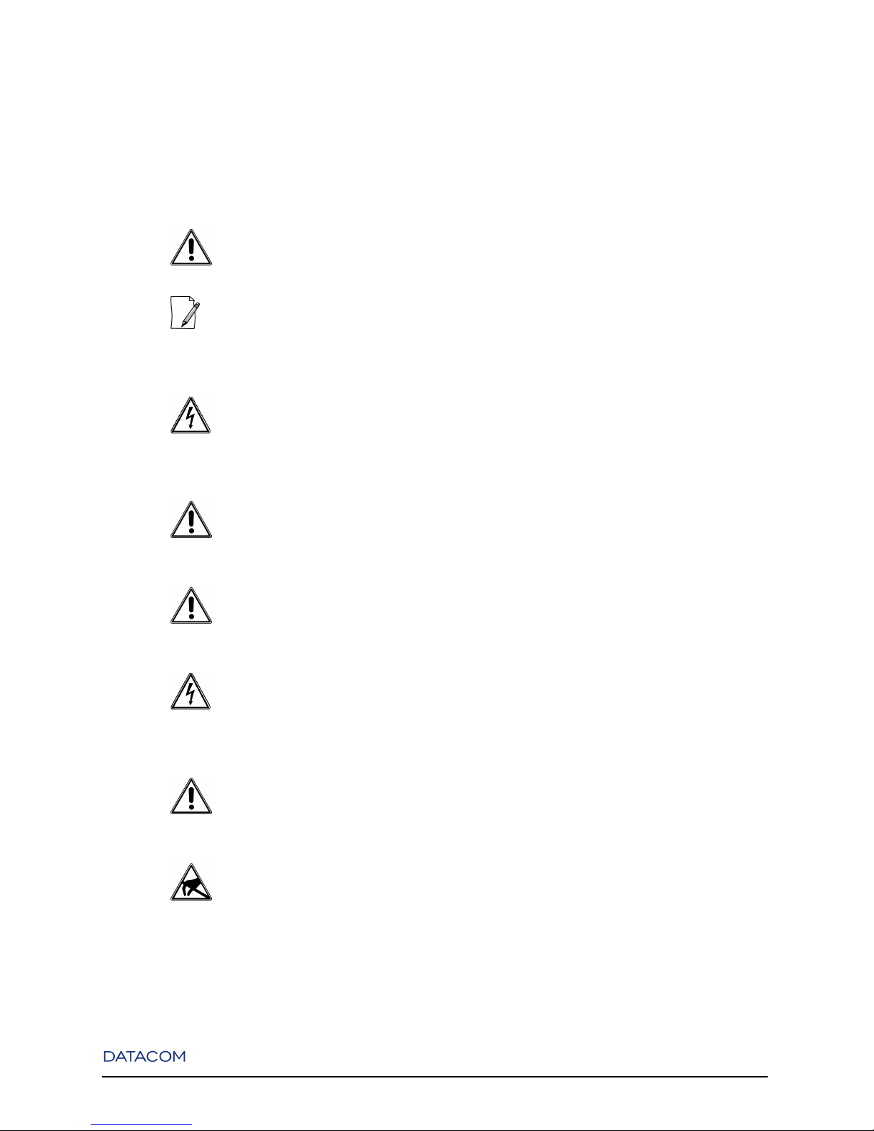
Safety information
Symbol Description
Generic alarm symbol: To suggest a general
safety
ESD protection symbol: To suggest
electrostatic-sensitive equipment
Electric shock symbol: To suggest a danger of
high voltage
Microwave symbol: To suggest a high-intensity
electromagnetic field
Laser symbol: To suggest a strong laser beam

Table of Contents
1. General Recommendation.....................................................................................................................1
1.1. Before the Installation.................................................................................................................1
2. Introduction............................................................................................................................................3
2.1. About this guide ..........................................................................................................................3
2.2. Overview.....................................................................................................................................3
3. Technical Specifications.........................................................................................................................7
3.1. Environmental Conditions...........................................................................................................7
3.2. Power Supply ..............................................................................................................................7
3.2.1. DM4001..........................................................................................................................7
3.2.2. DM4004..........................................................................................................................8
3.2.3. DM4008..........................................................................................................................9
3.2.4. Interface Modules...........................................................................................................9
3.3. Dimensions................................................................................................................................10
3.4. Weight .......................................................................................................................................10
4. DM4001 Chassis...................................................................................................................................13
4.1. Overview...................................................................................................................................13
4.2. Front Panel Description.............................................................................................................13
4.3. System Status LEDs..................................................................................................................14
4.4. Console and Ethernet Outband Management Ports ..................................................................15
4.5. Rear Panel Description..............................................................................................................16
5. DM4004 Chassis...................................................................................................................................17
5.1. Overview...................................................................................................................................17
5.2. Front Panel Description.............................................................................................................18
5.3. Rear Panel Description..............................................................................................................19
5.4. Console Management Port ........................................................................................................20
6. DM4008 Chassis...................................................................................................................................22
6.1. Overview...................................................................................................................................22
6.2. Front Panel Description.............................................................................................................22
6.3. Rear Panel Description..............................................................................................................23
6.4. Console Management Port ........................................................................................................24
7. DM4000 MPU192.................................................................................................................................26
7.1. Overview...................................................................................................................................26
7.2. Front Panel Description.............................................................................................................27
7.3. System Status LEDs..................................................................................................................27
7.4. Console and Ethernet Outband Management Ports ..................................................................28
8. DM4000 MPU384.................................................................................................................................30
8.1. Overview...................................................................................................................................30
8.2. Front Panel Description.............................................................................................................31
8.3. System Status LEDs..................................................................................................................31
8.4. Console and Ethernet Outband Management Ports ..................................................................32
vi

9. DM4000 MPU416.................................................................................................................................34
9.1. Overview...................................................................................................................................34
9.2. Front Panel Description.............................................................................................................35
9.3. System Status LEDs..................................................................................................................35
9.4. Console and Ethernet Outband Management Ports ..................................................................36
10. DM4000 ETH24GX ........................................................................................................................... 38
10.1. Overview.................................................................................................................................38
10.2. Front Panel Description...........................................................................................................39
10.3. System Status LEDs................................................................................................................39
10.4. Software and Hardware Features ............................................................................................40
10.4.1. Software......................................................................................................................40
10.4.2. Hardware ....................................................................................................................40
11. DM4000 ETH24GX H Series............................................................................................................42
11.1. Overview.................................................................................................................................42
11.2. Front Panel Description...........................................................................................................42
11.3. System Status LEDs................................................................................................................43
11.4. Software and Hardware Features ............................................................................................44
11.4.1. Software......................................................................................................................44
11.4.2. Hardware ....................................................................................................................44
12. DM4000 ETH12GX ........................................................................................................................... 46
12.1. Overview.................................................................................................................................46
12.2. Front Panel Description...........................................................................................................47
12.3. System Status LEDs................................................................................................................47
12.4. Software and Hardware Features ............................................................................................48
12.4.1. Software......................................................................................................................48
12.4.2. Hardware ....................................................................................................................48
13. DM4000 ETH12GX+1x10GX...........................................................................................................50
13.1. Overview.................................................................................................................................50
13.2. Front Panel Description...........................................................................................................51
13.3. System Status LEDs................................................................................................................51
13.4. Software and Hardware Features ............................................................................................52
13.4.1. Software......................................................................................................................52
13.4.2. Hardware ....................................................................................................................52
14. DM4000 ETH2x10GX ....................................................................................................................... 54
14.1. Overview.................................................................................................................................54
14.2. Front Panel Description...........................................................................................................55
14.3. System Status LEDs................................................................................................................56
14.4. Software and Hardware Features ............................................................................................56
14.4.1. Software......................................................................................................................56
14.4.2. Hardware ....................................................................................................................56
15. DM4000 ETH24GT ...........................................................................................................................58
15.1. Overview.................................................................................................................................58
15.2. Front Panel Description...........................................................................................................58
15.3. System Status LEDs................................................................................................................59
15.4. Software and Hardware Features ............................................................................................60
vii

15.4.1. Software......................................................................................................................60
15.4.2. Hardware ....................................................................................................................60
16. DM4000 ETH48GT ...........................................................................................................................62
16.1. Overview.................................................................................................................................62
16.2. Front Panel Description...........................................................................................................62
16.3. System Status LEDs................................................................................................................63
16.4. Software and Hardware Features ............................................................................................64
16.4.1. Software......................................................................................................................64
16.4.2. Hardware ....................................................................................................................64
17. DM4000 ETH48GX H Series............................................................................................................66
17.1. Overview.................................................................................................................................66
17.2. Front Panel Description...........................................................................................................66
17.3. System Status LEDs................................................................................................................67
17.4. Software and Hardware Features ............................................................................................68
17.4.1. Software......................................................................................................................68
17.4.2. Hardware ....................................................................................................................68
18. DM4000 ETH24GX+2x10GX H Series............................................................................................70
18.1. Overview.................................................................................................................................70
18.2. Front Panel Description...........................................................................................................70
18.3. System Status LEDs................................................................................................................71
18.4. Software and Hardware Features ............................................................................................72
18.4.1. Software......................................................................................................................72
18.4.2. Hardware ....................................................................................................................72
19. DM4000 ETH2x10GX H Series........................................................................................................74
19.1. Overview.................................................................................................................................74
19.2. Front Panel Description...........................................................................................................74
19.3. System Status LEDs................................................................................................................75
19.4. Software and Hardware Features ............................................................................................76
19.4.1. Software......................................................................................................................76
19.4.2. Hardware ....................................................................................................................76
20. DM4000 ETH4x10GX H Series........................................................................................................78
20.1. Overview.................................................................................................................................78
20.2. Front Panel Description...........................................................................................................78
20.3. System Status LEDs................................................................................................................79
20.4. Software and Hardware Features ............................................................................................80
20.4.1. Software......................................................................................................................80
20.4.2. Hardware ....................................................................................................................80
21. DM4000 GPC-OAB ........................................................................................................................... 82
21.1. Overview.................................................................................................................................82
21.2. Front Panel Description...........................................................................................................83
22. DM4000 GPC-OAP............................................................................................................................84
22.1. Overview.................................................................................................................................84
22.2. Front Panel Description...........................................................................................................85
viii

23. DM4000 GPC-DCM ..........................................................................................................................86
23.1. Overview.................................................................................................................................86
23.2. Front Panel Description...........................................................................................................87
24. Fan Board ...........................................................................................................................................88
24.1. Description ..............................................................................................................................88
24.2. Air Flow ..................................................................................................................................89
24.2.1. DM4004 and DM4008 Chassis ..................................................................................89
25. Installation Guide ..............................................................................................................................91
25.1. Installation Kit.........................................................................................................................91
25.2. Powering the Switch ...............................................................................................................92
25.2.1. Cables .........................................................................................................................94
25.3. Installing the FAN Module in the Chassis ..............................................................................96
25.4. Removing the FAN Module of the Chassis.............................................................................97
25.5. Inserting the Interface Board in the Chassis ...........................................................................98
25.6. SFP Module...........................................................................................................................100
25.6.1. Connecting a SFP Module........................................................................................ 101
25.6.2. Removing SFP Modules........................................................................................... 102
25.6.3. Transceivers Homologation Check...........................................................................103
A. Cable DB9-RJ-45 ..............................................................................................................................104
A.1. Construction ...........................................................................................................................104
B. Optical Amplifiers .............................................................................................................................106
B.1. How to connect an optical amplifier and a interface board....................................................106
C. Applicable Standards........................................................................................................................107
C.1. Applicable Standards for DM4000 family .............................................................................107
ix

List of Tables
3-1. Recommended Power Limits and Consumption Parameters for DM4001 ..........................................7
3-2. Absolute Power Limits for DM4001..................................................................................................??
3-3. Recommended Power Limits and Consumption Parameters for DM4004 ..........................................8
3-4. Absolute Power Limits for DM4004....................................................................................................8
3-5. Recommended Power Limits and Consumption Parameters for DM4008 ..........................................9
3-6. Absolute Power Limits for DM4008....................................................................................................9
3-7. Consumption and Fuse .........................................................................................................................9
3-8. Chassis................................................................................................................................................10
3-9. FANs...................................................................................................................................................10
3-10. MPUs................................................................................................................................................11
3-11. Interface Boards ...............................................................................................................................11
3-12. GPC Boards......................................................................................................................................11
3-13. Blank Panels .....................................................................................................................................11
4-1. System LEDs DM4001 Chassis ......................................................................................................... 15
4-2. Interface Pinout ..................................................................................................................................16
5-1. DB9 Pins Specification.......................................................................................................................21
6-1. DB9 Pins Specification.......................................................................................................................25
7-1. MPU192 System LEDs ...................................................................................................................... 28
7-2. Interface Pinout ..................................................................................................................................29
8-1. MPU384 System LEDs ...................................................................................................................... 32
8-2. Interface Pinout ..................................................................................................................................33
9-1. MPU416 System LEDs ...................................................................................................................... 36
9-2. Interface Pinout ..................................................................................................................................37
10-1. ETH24GX Port Status LEDs............................................................................................................40
10-2. Hardware DM4000 ETH24GX ........................................................................................................41
11-1. ETH24GX H Series Port Status LEDs .............................................................................................44
11-2. Hardware DM4000 ETH24GX H Series..........................................................................................45
12-1. ETH12GX Port Status LEDs............................................................................................................48
12-2. Hardware DM4000 ETH12GX ........................................................................................................49
13-1. ETH12GX+1x10GX Port Status LEDs............................................................................................52
13-2. Hardware DM4000 ETH12GX+1x10GX ........................................................................................53
14-1. ETH2x10GX Port Status LEDs........................................................................................................56
14-2. Hardware DM4000 ETH2x10GX ....................................................................................................57
15-1. ETH24GT Port Status LEDs ............................................................................................................??
15-2. Hardware DM4000 ETH24GT.........................................................................................................61
16-1. ETH48GT Port Status LEDs ............................................................................................................??
16-2. Hardware DM4000 ETH48GT.........................................................................................................65
17-1. ETH48GX H Series Port Status LEDs .............................................................................................??
17-2. Hardware DM4000 ETH48GX H Series..........................................................................................69
18-1. ETH24GX+2x10GX H Series Port Status LEDs.............................................................................72
18-2. Hardware DM4000 ETH24GX+2x10GX H Series..........................................................................73
19-1. ETH2x10GX H Series Port Status LEDs .........................................................................................76
19-2. Hardware DM4000 ETH2x10GX H Series......................................................................................77
20-1. ETH4x10GX H Series Port Status LEDs .........................................................................................80
20-2. Hardware DM4000 ETH4x10GX H Series......................................................................................81
21-1. Booster parameters ...........................................................................................................................83
x

21-2. DM4000 GPC-OAB Port Status LEDs ............................................................................................ 83
22-1. Pre-amplifier parameters ..................................................................................................................85
22-2. DM4000 GPC-OAP Port Status LEDs.............................................................................................85
23-1. DCM parameters ..............................................................................................................................87
25-1. Cable dimension according chassis..................................................................................................94
25-2. Gigabit SFP Modules .....................................................................................................................102
A-1. Cable DB9-RJ-45 ............................................................................................................................104
C-1. Applicable Standards .......................................................................................................................107
xi
Chapter 1. General Recommendation
1.1. Before the Installation
"Before the installation, read the entire manual attentively."
"The installation of any electric equipment must be in accordance with the current law in the place
where this equipment will be installed. This includes adequate devices of protection, sizing and protection
to the capacities of the equipment."
"Always observe the instructions of security during the installation, operation or maintenance of
this product. Installation, adjustment or maintenance must be carried through only by qualified, trained
and authorized people."
"The power supply, where the supply cable is connected, must be positioned near the equipment
and be on an easily accessible location, because the equipment is turned on and off through it."
"Follow intently every guidance included in this manual. In case of doubts, please contact the
authorized technical support."
"All slots that are not occupied with boards must be closed with a blank panel. Thus, you avoid the
exposure to the energized parts inside the equipment. This procedure must be performed only by a trained
and authorized person."
"When installing the equipment, always tighten screws and knurling screws until the end of their
thread and until they are completely tightened."
"The described equipment in this manual is sensible to the static electricity. Before handling
any equipment described in this manual, verify if the devices of protection against static electricity are
functioning correctly."
1
Chapter 1. General Recommendation
"Some equipment in this manual have laser emitting optical modules. Avoid the exposure to eyes
and skin."
"WEEE Directive Symbol (Applicable in the European Union and other European countries
with separate collection systems).This symbol on the product or its packaging indicates that this product
must not be disposed of with other waste. Instead, it is your responsibility to dispose of your waste equipment by handing it over to a designated collection point for the recycling of waste electrical and electronic
equipment. The separate collection and recycling of your waste equipment at the time of disposal will help
conserve natural resources and ensure that it is recycled in a manner that protects human health and the
environment. For more information about where you can drop off your consumer waste equipment for recycling, please contact your local city recycling office or the dealer from whom you originally purchased
the product."
2
Chapter 2. Introduction
2.1. About this guide
This guide can be used for all DATACOM DM4000 Metro Ethernet Series, providing information about
installation and characteristics of the DM4000 family.
This guide focuses on the physical, electrical, status indications and installation portion of the hardware. It
is assumed that the individual or individuals managing any aspect of this product have basic understanding
of Switching, Routing, Ethernet, and general Telecommunications.
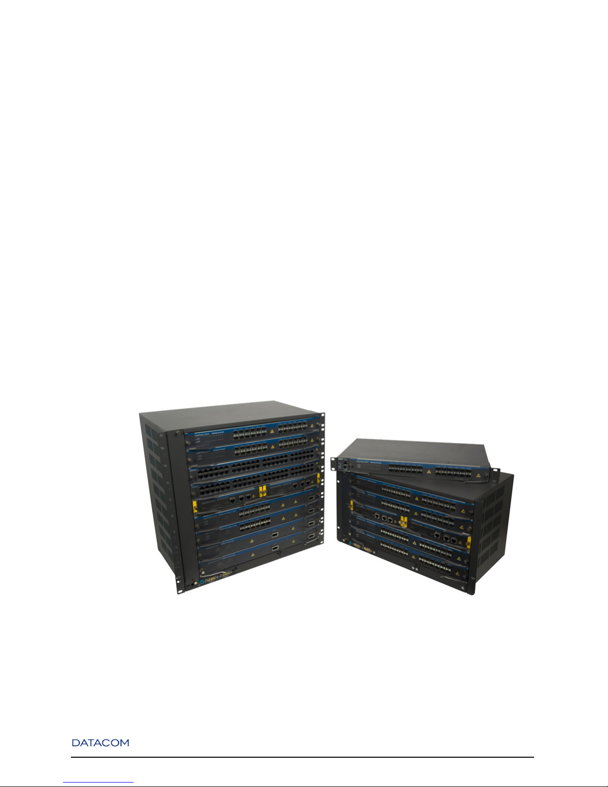
2.2. Overview
Figure 2-1. DM4000 Series - DM4008(left), DM4004(right, below) and DM4001(right, above)
The DM4000 Metro Ethernet Switches offer the best and most reliable solution for Fast, Gigabit and 10
Gigabit Ethernet deployments. Supporting copper and fiber connections, DATACOM DM4000 switches
3

Chapter 2. Introduction
can be used to connect to clients, servers or access devices (hubs, routers, LAN switches or WAN access
devices).
DM4000 Metro Ethernet Series provides multiple chassis options to connect and manage non-blocking
data between boards. Its scalable platform design allows future growth and investment protection from
the smallest to the largest chassis option.
The DM4000 Series provide several optional interface modules with all chassis sizes, and may be configured to support redundant MPUs (Main Processor Units), compatible with either the 6U (DM4004) and/or
the 10U (DM4008) height chassis, following your network growth and guaranteeing advanced reliability
for your network.
For complete management, CLI, Web, SNMP and DmView tools are available. The DmView tool is a
Graphical User Interface that allows complete state and fail monitoring conditions, configuration management and inventory, perfect for higher network sizes.
DM4000 Series is the perfect choice for the core of your network, ensuring its reliability and scalability.
The Chassis models available are as follows:
• DM4001 Chassis - 19" 1U height Chassis compatible with all DM4000 interface modules.
• DM4004 Chassis - 19" and 23" 6U height Chassis with 4 interface slots, 2 MPU slots and a FAN slot.
• DM4008 Chassis - 19" 10U height Chassis with 8 interface slots, 2 MPU slots and a FAN slot.
Interface Modules available in DM4000 Series:
• DM4000 ETH24GX - Hot swappable 24 ports SFP Gigabit Ethernet switch interface board. SFPs are
1000Base-X and SGMII compatible.
• DM4000 ETH24GX H Series - Hot swappable 24 ports SFP Gigabit Ethernet switch interface board.
SFPs are 100Base-FX, 1000Base-X and SGMII compatible.
• DM4000 ETH12GX - Hot swappable 12 ports SFP Gigabit Ethernet switch interface board. SFPs are
1000Base-X and SGMII compatible.
• DM4000 ETH12GX+1x10GX - Hot swappable 12 ports SFP Gigabit Ethernet switch plus one 10 Gi-
gabit XFP interface board. SFPs are 1000Base-X and SGMII compatible.
• DM4000 ETH24GX+2x10GX H Series - Hot swappable 24 ports SFP Gigabit Ethernet switch plus two
10 Gigabit XFP interface board. SFPs are 100Base-FX, 1000Base-X and SGMII compatible.
• DM4000 ETH2x10GX - Hot swappable 2 ports 10 Gigabit XFP interface board.
4

Chapter 2. Introduction
• DM4000 ETH2x10GX H Series - Hot swappable 2 ports 10 Gigabit XFP interface board.
• DM4000 ETH24GT - Hot swappable 24 ports 10/100/1000Base-T Ethernet switch interface board.
• DM4000 ETH48GT - Hot swappable 48 ports 10/100/1000Base-T Ethernet switch interface board.
• DM4000 ETH48GX H Series - Hot swappable 48 ports SFP Gigabit Ethernet switch interface board.
SFPs are 100Base-FX, 1000Base-X and SGMII compatible.
• DM4000 ETH4x10GX H Series - Hot swappable 4 ports 10 Gigabit XFP interface board.
MPUs (Main Processor Unit) available in DM4000 Series:
• DM4000 MPU192 - Non-blocking, redundant and hot swappable Main Processor Unit, capable of
switching 192Gbit/s of data.
• DM4000 MPU384 - Non-blocking, redundant and hot swappable Main Processor Unit, capable of
switching 384Gbit/s of data.
• DM4000 MPU416 - Non-blocking, redundant and hot swappable Main Processor Unit, capable of
switching 416Gbit/s of data.
FAN interfaces available in DM4000 Series:
• DM4004 FAN - Hot swappable FAN module for DM4004 Chassis 19".
• DM4004 23" FAN - Hot swappable FAN module for DM4004 Chassis 23".
• DM4008 FAN - Hot swappable FAN module for DM4008 Chassis.
GPC available in DM4000 Series:
• DM4000 GPC-OAB - Hot swappable optical booster amplifier.
• DM4000 GPC-OAP - Hot swappable optical pre-amplifier.
• DM4000 GPC-DCM - Hot swappable Dispersion Compensation Module.
Some combinations of Interface Boards and MPUs are unsupported due to the system internal architecture.
These combinations are listed bellow:
• DM4000 ETH2x10GX using a MPU192 in a DM4008 Chassis
• DM4000 ETH24GX using a MPU192 in a DM4008 Chassis
5

Chapter 2. Introduction
• DM4000 ETH12GX+1x10GX using a MPU192 in a DM4008 Chassis
Different MPUs cannot be used in the same chassis. You must use both MPUs of the same type (two
MPU192, MPU384 or MPU416)
6
Chapter 3. Technical Specifications
3.1. Environmental Conditions
Operating Temperature: 0 to 55 degrees Celsius
Storage Temperature: -20 to 65 degrees Celsius
Humidity: 10 to 90% non condensing
3.2. Power Supply
The DM4000 family has a DC power input range of -48 to -60 V
WARNING:
"Before connecting any cable to the equipment, be sure that the grounding system is functional."
WARNING:
"The power supply, where the supply cable is connected, must be positioned near the equipment and have
easy access, because the equipment is turned on and off through it."
3.2.1. DM4001
Table 3-1. Recommended Power Limits and Consumption Parameters for DM4001
Rec. Voltage Limits Power Type Power max. Current max.
min. max.
-48V -60V DC 200W 3.5A
7
Chapter 3. Technical Specifications
Table 3-2. Absolute Power Limits for DM4001
Absolute Voltage Limits Power Type Power max. Current max.
min. max.
-36V -72V DC 200W 4.7A
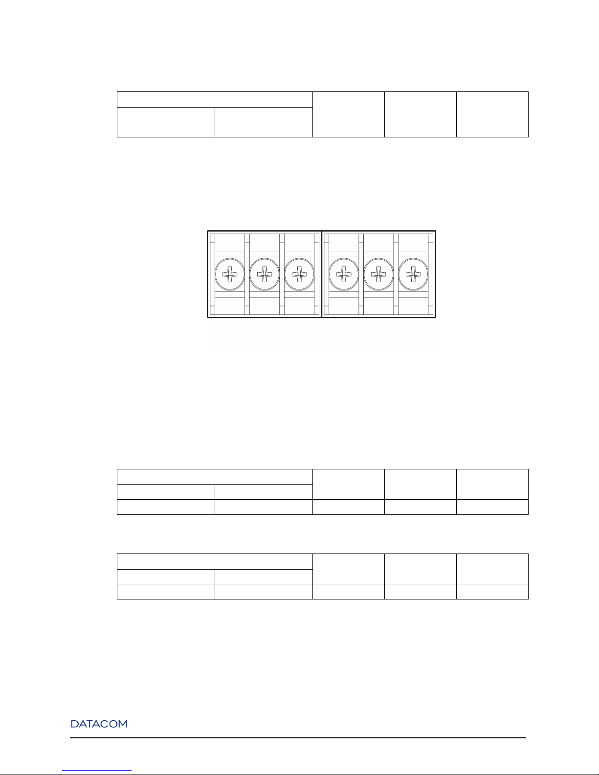
Follow Power information below screws to correct RET / -48V connections
Figure 3-1. DM4001 Power Supplies Connectors
3.2.2. DM4004
Table 3-3. Recommended Power Limits and Consumption Parameters for DM4004
Rec. Voltage Limits Power Type Power max. Current max.
min. max.
-48V -60V DC 576W 12.00A
Table 3-4. Absolute Power Limits for DM4004
Absolute Voltage Limits Power Type Power max. Current max.
min. max.
-36V -72V DC 576W 16.00A
8

Chapter 3. Technical Specifications
Figure 3-2. DM4004 Power Supplies Connectors
3.2.3. DM4008
Table 3-5. Recommended Power Limits and Consumption Parameters for DM4008
Rec. Voltage Limits Power Type Power max. Current max.
min. max.
-48V -60V DC 1200W 25.00A
Table 3-6. Absolute Power Limits for DM4008
Absolute Voltage Limits Power Type Power max. Current max.
min. max.
-36V -72V DC 1200W 33.33A
Figure 3-3. DM4008 Power Supplies Connectors
3.2.4. Interface Modules
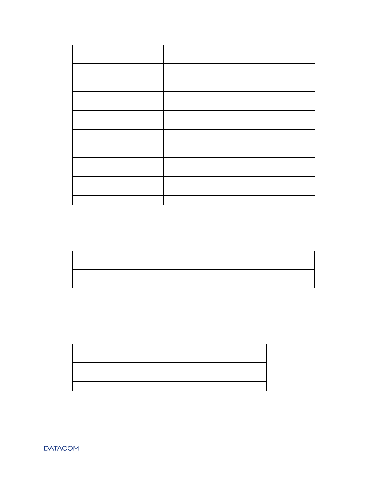
Table 3-7. Consumption and Fuse
Interface Module Fuse Consumption
ETH24GX 3.15A fuse, type T (delay), 250V 90W
ETH24GX H Series 3.15A fuse, type T (delay), 250V 70W
ETH12GX 3.15A fuse, type T (delay), 250V 45W
ETH12GX+1x10GX 3.15A fuse, type T (delay), 250V 80W
ETH24GX+2x10GX H Series 3.15A fuse, type T (delay), 250V 80W
9
Chapter 3. Technical Specifications
Interface Module Fuse Consumption
ETH2x10GX 3.15A fuse, type T (delay), 250V 70W
ETH2x10GX H Series 3.15A fuse, type T (delay), 250V 70W
ETH24GT 3.15A fuse, type T (delay), 250V 55W
ETH48GT 3.15A fuse, type T (delay), 250V 110W
ETH48GX H Series 3.15A fuse, type T (delay), 250V 85W
ETH4x10GX H Series 3.15A fuse, type T (delay), 250V 70W
MPU192 3.15A fuse, type T (delay), 250V 20W
MPU384 3.15A fuse, type T (delay), 250V 30W
MPU416 3.15A fuse, type T (delay), 250V 30W
GPC-OAB 3.15A fuse, type T (delay), 250V 10W
GPC-OAP 3.15A fuse, type T (delay), 250V 10W
GPC-DCM NA NA
DM4001 3.15A fuse, type T (delay), 250V 22W
DM4004 FAN 3.15A fuse, type T (delay), 250V 30W
DM4004 23" FAN 3.15A fuse, type T (delay), 250V 30W
DM4008 FAN 3.15A fuse, type T (delay), 250V 100W
3.3. Dimensions
Height 240 mm (DM4004), 400mm (DM4008) and 44mm (DM4001)
Width w/o brackets 440mm in 19” chassis and 541.4mm in 23” chassis
Width with brackets 483mm in 19” chassis and 584.2mm in 23” chassis
Depth 280 mm (DM4004, DM4008 and DM4001)
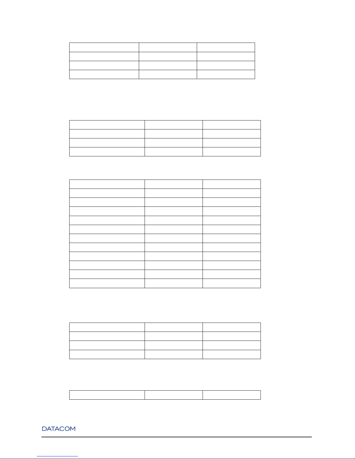
3.4. Weight
Table 3-8. Chassis
Chassis Kilograms (kg) Pounds (lbs)
DM4001 2.86 6.29
DM4004 19" 8.21 18.09
DM4004 23" 10.10 22.26
DM4008 11.57 25.51
Table 3-9. FANs
10
Chapter 3. Technical Specifications
FAN Kilograms (kg) Pounds (lbs)
DM4004 19" 1.49 3.28
DM4004 23" 1.31 2.89
DM4008 2.68 5.90
Table 3-10. MPUs
MPU Kilograms (kg) Pounds (lbs)
MPU192 0.97 2.13
MPU384 1.12 2.47
MPU416 1.12 2.47
Table 3-11. Interface Boards
Interface Board Kilograms (kg) Pounds (lbs)
ETH24GX 2.49 5.49
ETH24GX H Series 2.49 5.49
ETH12GX 2.30 5.07
ETH12GX+1x10GX 2.39 5.27
ETH24GX+2x10GX H Series 2.74 6.03
ETH2x10GX 2.35 5.17
ETH2x10GX H Series 2.35 5.17
ETH24GT 2.49 5.49
ETH48GT 2.78 6.12
ETH48GX H Series 2.91 6.42
ETH4x10GX H Series 2.52 5.54
Table 3-12. GPC Boards
GPC Kilograms (kg) Pounds (lbs)
GPC-OAB 0.41 0.90
GPC-OAP 0.41 0.90
GPC-DCM 0.41 0.90
Table 3-13. Blank Panels
Panel Kilograms (kg) Pounds (lbs)
11

Chapter 3. Technical Specifications
Panel Kilograms (kg) Pounds (lbs)
Interface Boards Blank Panel 2.68 5.90
MPUs Blank Panel 0.09 0.19
GPCs Blank Panel 0.05 0.11
12
Chapter 4. DM4001 Chassis
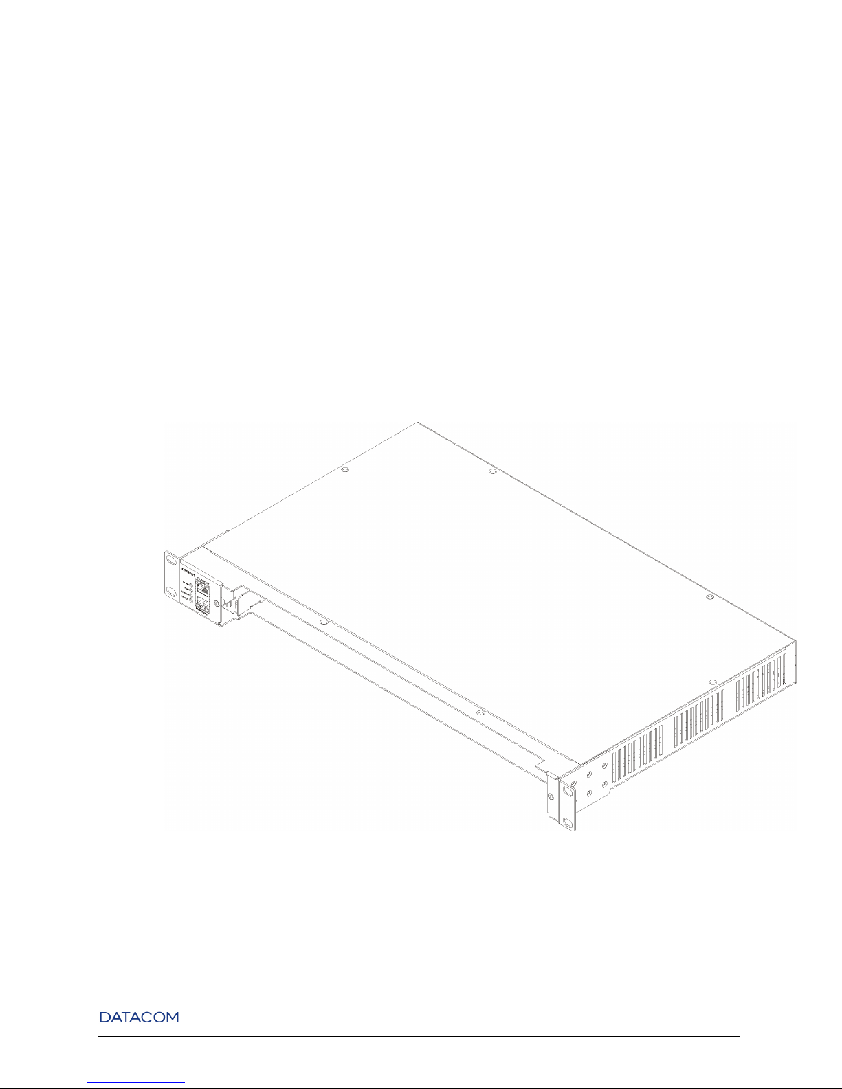
4.1. Overview
The DM4001 chassis is compatible with all interface boards of the DM4000 Series, allowing their utilization as a standalone version.
Its backplane interface allows non-blocking wire speed data of all interface boards connected.
Each interface board has temperature sensors that allow DM4001 chassis electronic fan control to manage
fan speed increasing equipment reliability and minimizing fan noise.
Figure 4-1. DM4001 Chassis
13
Chapter 4. DM4001 Chassis
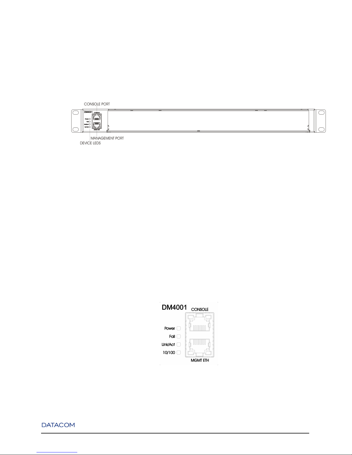
4.2. Front Panel Description
The Front Panel of the DM4001 chassis has a RS232 Console port, an Ethernet Outband Management
interface and Status LEDs.
Figure 4-2. DM4001 Chassis - Front Panel
4.3. System Status LEDs
The System Status LEDs on the front panel can be used to monitor system activity. The following figure
shows where the LEDs are located and the table below indicates the system status according to each LEDs
condition.
Figure 4-3. DM4001 Chassis - Front Panel LEDs
14
Chapter 4. DM4001 Chassis
Table 4-1. System LEDs DM4001 Chassis
LED CONDITION STATUS
Power ON Equipment on.
OFF Equipment off.
Fail ON Indicates fail (high temperature or fan fail).
OFF Equipment operates normally.
Link/Act ON/Blinking Connected with link up. Blinking indicates
activity.
OFF No connection established.
Speed ON 10Mbit/s connection established.
OFF Indicates a 100Mbit/s Connection when Link/Act
LED is ON or Blinking.
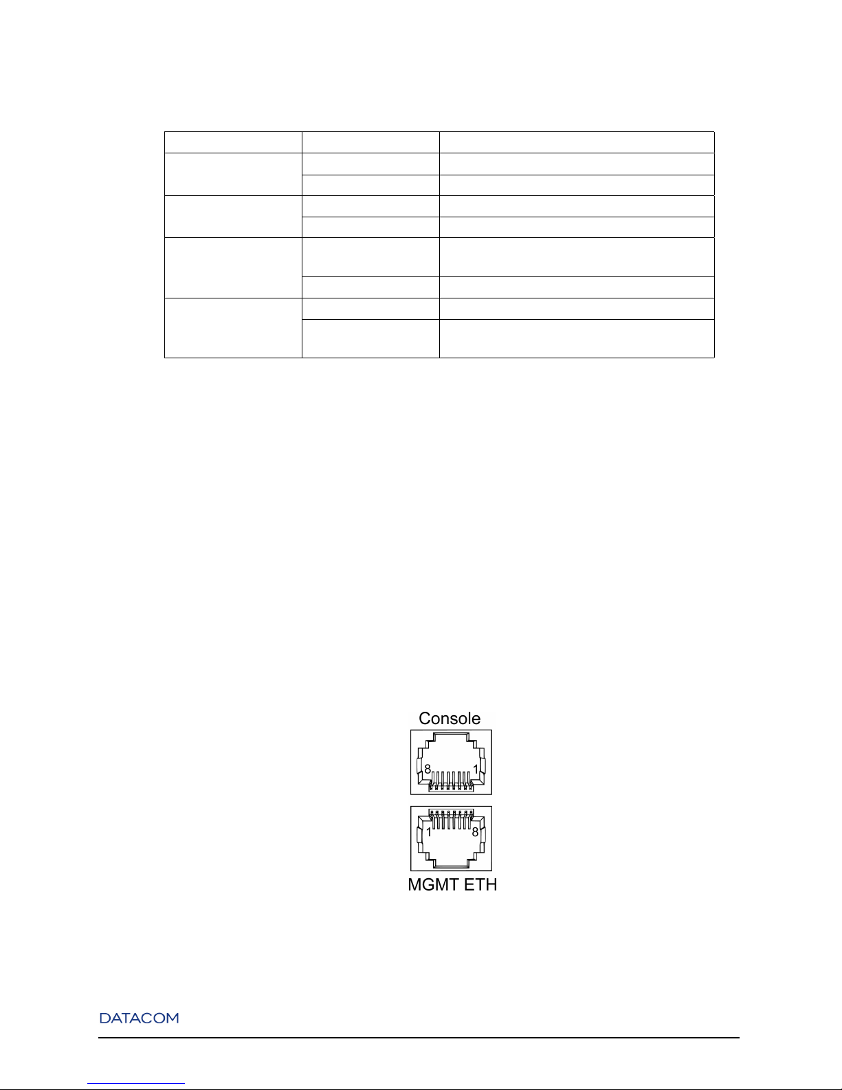
4.4. Console and Ethernet Outband Management Ports
The switch contains two RJ-45 connectors on its front panel. The upper connector is the Console port and
the lower is the Outband Management port.
The Management port can be connected to a desktop through a CAT 5 Ethernet cable.
The pinouts of both Console and Outband Management ports are shown in the following figure and table.
Figure 4-4. Double RJ-45 Connector
15
Chapter 4. DM4001 Chassis
Table 4-2. Interface Pinout
Management Port
RJ-45 Signal
1 Tx+
2 Tx-
3 Rx+
6 Rx-
4,5,7,8 -
RJ-45 Serial Port
1,2,7,8 -
3 Tx
4,5 GND
6 Rx
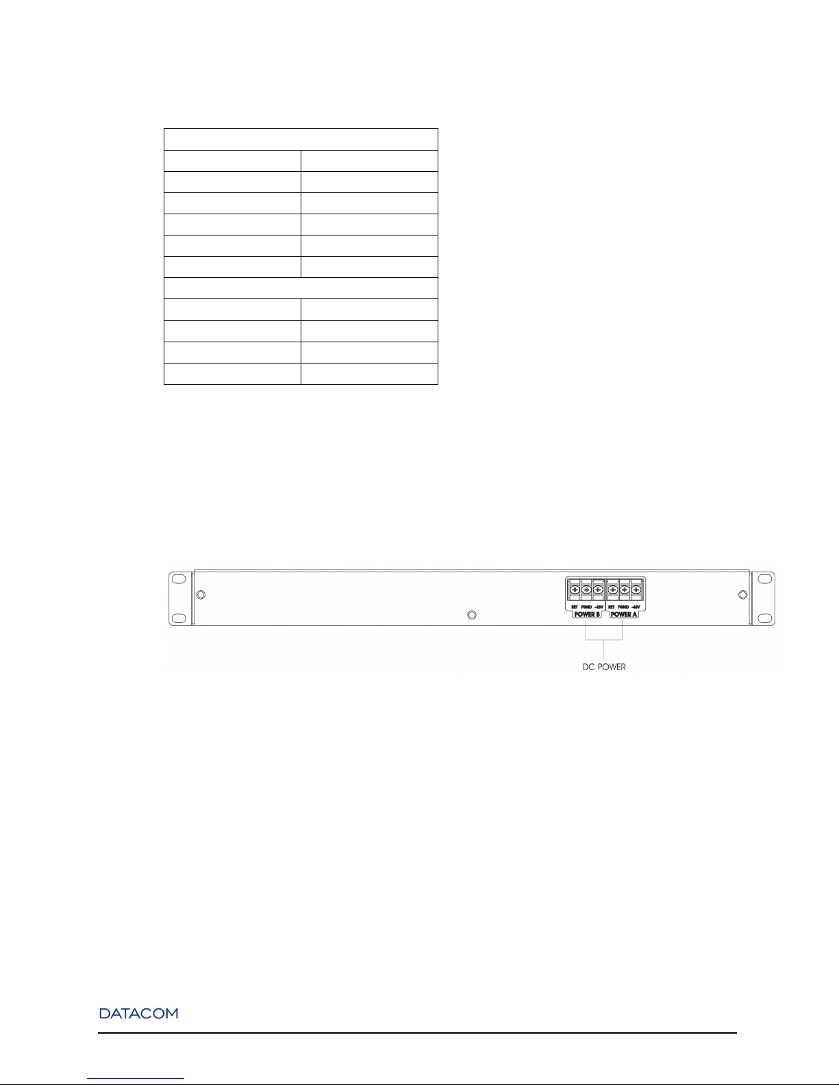
4.5. Rear Panel Description
The Rear Panel of the DM4001 chassis has two 48 to 60V DC power inputs.
Figure 4-5. DM4001 Rear Panel
Note: The figure above represents the last version of Rear Panel, another version could be different.
For your safety read the power indication.
16
Chapter 5. DM4004 Chassis
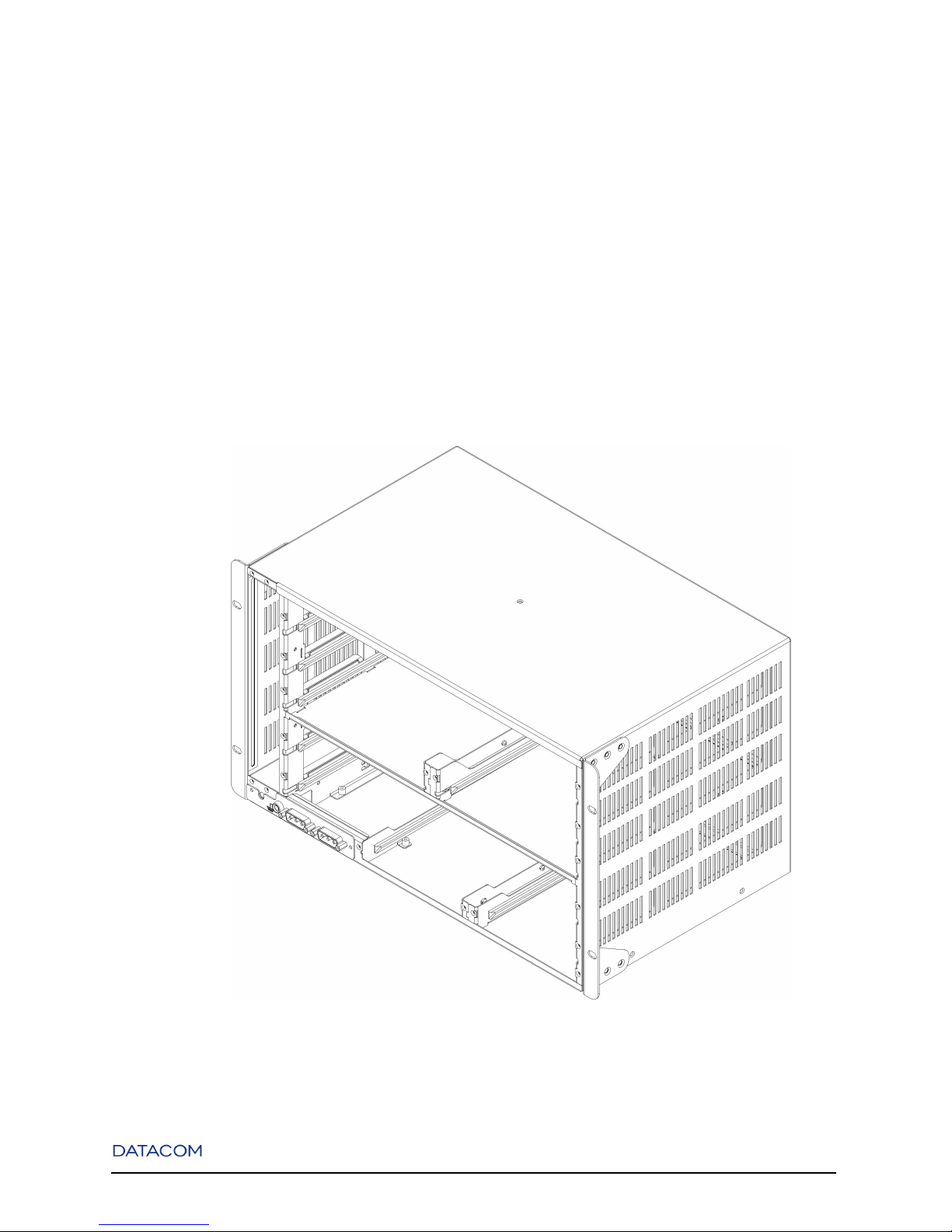
5.1. Overview
The DM4004 chassis is compatible with all MPUs and interface boards of the DM4000 Series. It is
available in two versions: for use in 19" and 23" racks. The 19" chassis is the standard version while the
23" has a better temperature perfomance and a dust filter option.
Both versions have a backplane that can handle up to 384Gbps of non-blocking data. They have four
interface board slots, two MPU slots, two general purpose slots and one FAN module slot.
Figure 5-1. DM4004 Chassis 19"
17
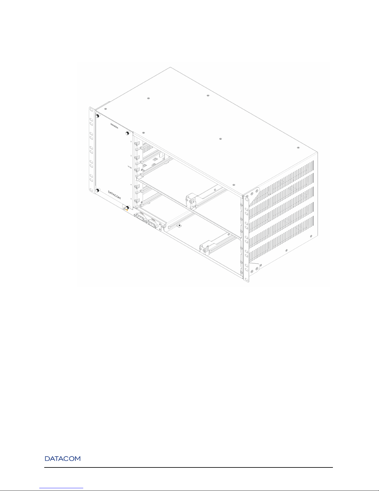
Chapter 5. DM4004 Chassis
Figure 5-2. DM4004 Chassis 23"
For normal operation blank panels are required for non slotted interface boards and MPUs.
5.2. Front Panel Description
The main power input connectors are located in the Front Panel of DM4004 chassis. It supports dual
redundant DC inputs for 48V DC nominal operation.
18
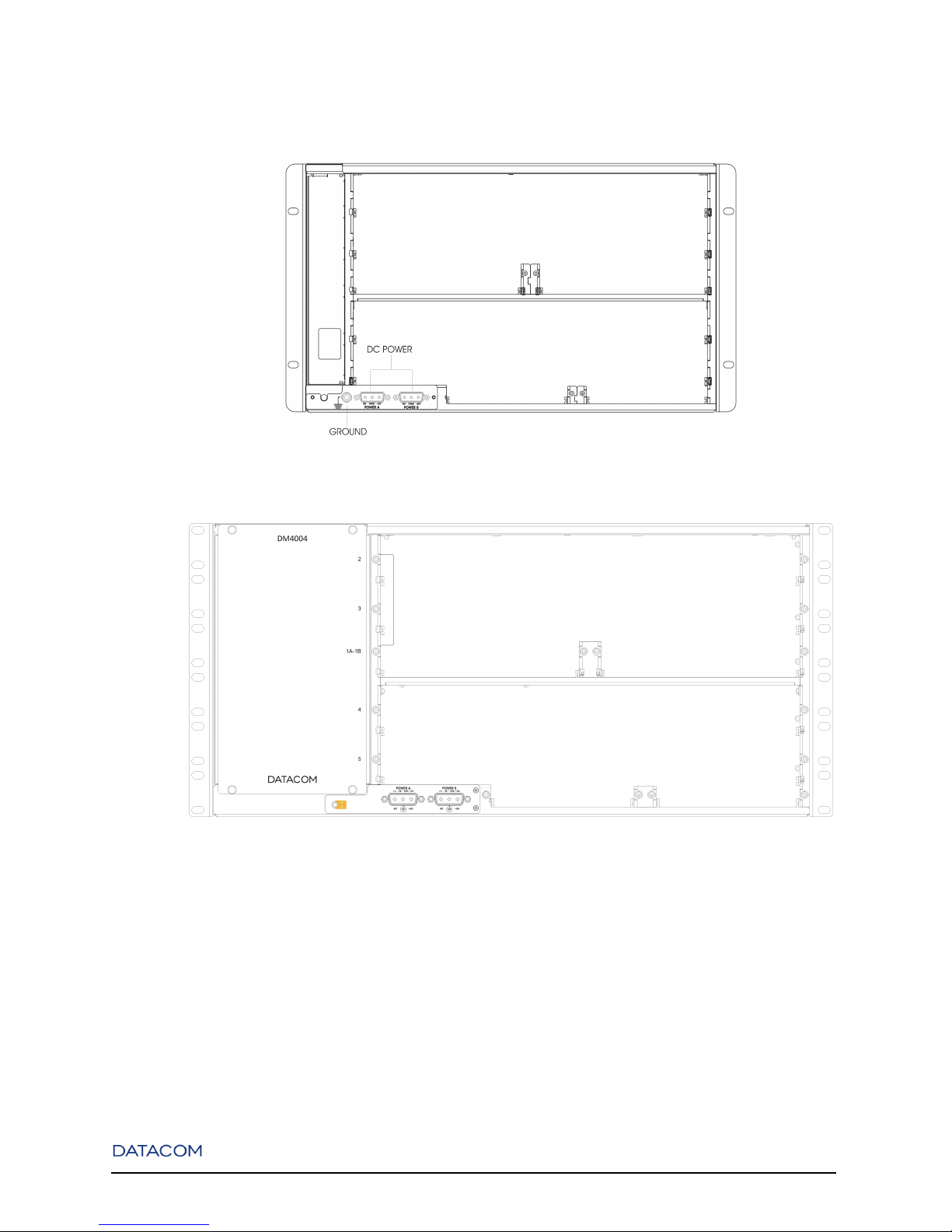
Chapter 5. DM4004 Chassis
Figure 5-3. DM4004 Chassis 19" - Front Panel
Figure 5-4. DM4004 Chassis 23" - Front Panel
5.3. Rear Panel Description
The DM4004 chassis Rear Panel has one console DB9 connector.
19
 Loading...