


ET-HF0101-TG200
ET-HF0101-RG200
VGA and Audio
Cat-X AV Extender
HDMI Fiber Optic Extender Kit
(Multi-mode SC type)
User Manual
◄ V1.0 ►
www.databay.com.tw
www.green-box.com.tw

- 1 -
Manual Contents
Manual Content P1
Product Description P2
System Requirements P3
Installation P4
Maintenance, Technical Support P5
Product Specifications P5
Regulatory Statements P6

Optical HDMI Extender user’s manual
Thank you for your purchase of the DataBay Optical HDMI (High Definition
Multimedia Interface) Extender. You now have a high quality and durable device to
extend high resolution content with the highest quality to 200 meters. This manual
contains will assist you in installing and operating the product.
Product Description
Shipping Group
¾ ET-HF0101-MG200 :
One (ET-HF0101-TG200) unit of transmitter
One (ET-HF0101-RG200) unit of receiver
¾ +5V AC/DC power adaptor:
Two power adapter with input 100~240V.
¾ HDMI cable :
1 pcs of length 1.8M
¾ User’s Manual
Figure 1 ET-HF0101-MG200 Transmitter and Receiver
US Plug EU Plug BS Plug
Figure 2 +5V AC/DC power adaptor (100~240V, 1A)
- 2 -

- 3 -
System Requirements for Setup
Hardware requirements
You have to have a HDMI port in your PC, DVD player or Multimedia playing device. It
should support the maximum graphic resolution feature of displays to be connected.
There is no other special requirement.
Software requirements
No special restrictions, if you’ve already properly installed your HDMI instrument.
Installation
Important: Please use the installation procedure below. Improper or no
operation may result if the start-up sequence is not correctly followed.
RX
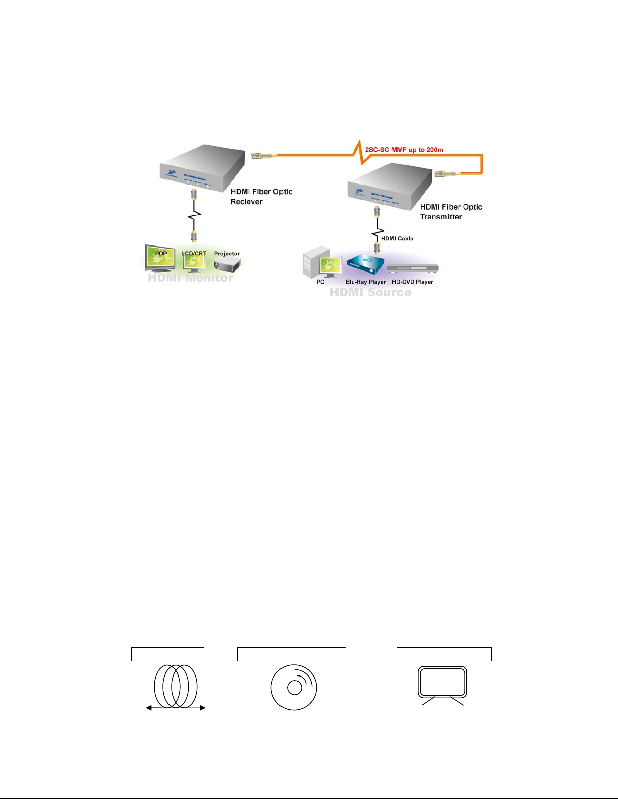
Figure 3 Installation of Optical HDMI extender
Installation Step
1. Put ‘TX’ module near to HDMI signal source, such as DVD players or
computers.
2. Put ‘RX’ module near to HDMI sink, such as LCD TVs or Projectors.
3. Connect HDMI cable from TX to Source. Also connect the HDMI cable from
RX to Sink.
4. Connect each duplex SC fiber cable as indicated number. The channel “1” of
TX corresponds to channel “1” of RX. The other channels are the same
connection.
5. Plug in the 5V adaptor to the electricity and TX/RX modules.
Note 1:Clean end face of fiber before plugging in. The dust will cause damage to the fiber.
Note 2:The length of HDMI cable should be NOT longer than 2 meters.
Note 3:These three figure s in front of the modules represent linking st atus. These 3 LEDs will be
bright greenly if all setups are complete and correct. The left one stands for the
connection of fiber. The middle one stands for the connection of HDMI sou rce. The right
one stands for the connection of HDMI source.
Optical fiber HDMI source cable HDMI sink cable
- 4 -

- 5 -
Maintenance
No special maintenance is required for the optical HDMI extender and power
supplies. Ensure that the TX, RX and power modules are stored or used in a
benign environment free from liquid or dirt contamination.
There are no user serviceable parts. Refer all service and repair issues to DataBay.
Technical Support and Service
For commercial or general product support, contact your reseller. For technical
service, contact DataBay by email sales@green-box.com
or visit its website at
www.green-box.com.tw
Product Specifications
PARAMETER SPECIFICATION NOTE
Max length 200M 62.5/125 MMF
Max resolution 1920 × 1080
HDCP compliant YES
CEC compliant YES
Operating voltage 5VDC
Electrical Power
consumption
TX: 3W
RX: 3W
5V/600mA
5V/600mA
Operating Temperature -10oC to 50 oC
Storage Temperatute -20 oC to 75 oC
Dimension 145 × 95 × 26 L × W × H (mm)
Weight 400g ± 5% TX or RX
Adaptor Specification
PARAMETER SPECIFICATION NOTE
Input 100~240VAC 0.2A 50~60Hz
Output DC 5V 1.0 A
DC Jack Inside 5V / Outside ground

- 6 -
FCC/CE Statement
This device complies with part 15 of FCC Rules and EN 55022/55024/61000-3 for CE
certification. Operation is subject to the following two conditions: (1) this device may
not cause harmful interference, and (2) this device must accept any interference
received, including interference that may cause undesired operation. This equipment
has been tested and found to comply with the limits for a Class A digital device,
pursuant to part 15 and 2 of FCC Rules and EN 55022/55024/61000-3 for CE
certification. These limits are designed to provide reasonable protection against
harmful interference when the equipment is operated in a residential installation. This
equipment generates, uses, and can radiate radio frequency energy and. if not
installed and used in accordance with the instruction guide, may cause harmful
interference to radio communications. However, there is no guarantee that
interference will not occur in a particular installation. If this equipment does cause
harmful interference to radio or television reception, which can be determined by
turning the equipment off and on, the user is encouraged to try to correct the
interference by one or more of the following measures:
¾ Re-orient or relocate the receiving antenna.
¾ Increase the separation between the equipment and the receiver.
¾ Connect the equipment into an outlet on a circuit different from that to which
the receiver is connected.
¾ Consult a service representative for help.
Properly shielded and grounded cables and connectors must be used in order to
comply with FCC/CE emission limits. Changes or modifications not expressly
approved by the party responsible for compliance could void the user s authority to
operate the equipment.

www.green-box.com.tw
GREEN-BOX TECHNOLOGY CO., LTD.
6F., No.20, Wuquan 8th Rd.,
Wugu District, New Taipei City 248, Taiwan (R.O.C.)
Tel: +886-2-2298-1289 Fax: +886-2-2298-0093
E-Mail:Sales@green-box.com.tw
- 7 -
 Loading...