

Page 1
ET-DF0101-TG500
ET-DF0101-RG500
User Manual
◄ V1.0 ►
www.databay.com.tw
www.green-box.com.tw
VGA and Audio
Cat-X AV Extender
DVI Fiber Optic Extender Kit
(Multi-mode LC type)
Page 2

- 1 -
Manual Contents
Manual Content P1
Product Description P2
System Requirements P3
Installation P4
Troubleshooting, Maintenance, Technical Support P5
Product Specifications P6
Warranty Information P7
Regulatory Statements P8
Pictorials
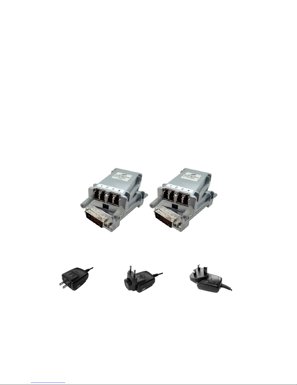
Figure 1 -- ET-DF0101-MG500 Transmitter and Receiver
P2
Figure 2 -- +5V AC/DC power adaptor (100~240V, 1A)
P2
Figure 3 -- Installation of Optical DVI extender P4
Page 3
- 2 -
Optical DVI Extender user’s manual
Thank you for your purchase of the DataBay Optical DVI (Digital Visual Interface)
Extender. You now have a high quality and durable device to extend high resolution
content with the highest quality to 500 meters. This manual contains will assist you in
installing and operating the product.
Product Description
Shipping Group
¾ ET-DF0101-MG500 :
One (ET-DF0101-TG500) unit of Transmitter
One (ET-DF0101-RG500) unit of Receiver.
¾ +5V AC/DC power adaptor:
Two power adapter with input 100~240V.
¾ User’s Manual
Figure 1 ET-DF0101-MG500 Transmitter and Receiver
US Plug EU Plug BS Plug
Figure 2 +5V AC/DC power adaptor (100~240V, 1A)
Page 4

- 3 -
System Requirements for Setup
Hardware requirements
You have to have a DVI graphic controller or card having a DVI port in your PC, SUN
or Mac systems. It should support the maximum graphic resolution feature of displays
to be connected. No special requirements memory size, CPU speed and chipsets, if
you’ve already properly installed your DVI graphic controllers or cards.
Software requirements
No special restrictions, if you’ve already properly installed your DVI graphic controller
in your OS.
Tip: In general, most of note PCs is not capable to supply sufficiently DC powers for two modules.
Page 5

- 4 -
Installation
Important: Please use the installation procedure below. Improper, or no
operation may result if the start-up sequence is not correctly followed.
Figure 3 Installation of Optical DVI extender
Installation Step
Step 1
Carefully unpack the contents of the shipping group.
Step 2
Connect each duplex LC fiber cable one by one as indicated number. The channel “1”
of TX corresponds to channel “1” of RX. The other channels are the same connection.
Step 3
Connect the AC/DC adaptor to the RX module.
Neglect AC/DC adaptor to the TX module. The PC may supply voltage source via DVI
receptacle.
Step 4
Plug directly the TX module in the DVI receptacle of PC. Do NOT use any
intermediate cable or adaptor between them.
Step 5
Plug the RX directly module in the DVI receptacle of display. Do NOT use any
intermediate cable or adaptor between them.
Step 6
Power on the PC and display.
Note1:The set-up of screen might be fitted to the display resolution. It is certain to happen such
unfitness if it is first time to boot up in using this extender module. Then, go to Display Properties in
Windows systems and click the tap of Settings. Then you can set the right display resolution to meet
your display. Once you set the right resolution, you could see displaying the initial screen at the same
resolution as just before you powered on.
Note2
:
You might not use the AC/DC adaptor at TX module, but use the power supplied through a DVI
pin from the graphic cards. After completing the installation instruction, if the system doesn’t work
properly, you could re-connect the AC/DC adaptor while all powers for the system are ON
Multimode Fiber (4LC)
Page 6

- 5 -
Troubleshooting
The display displays only black screen
Ensure that all AC and DC plugs and jacks used by external power supplies are
firmly connected. Ensure that the DVI ports are firmly plugged in to the PC and
display. Ensure that the Tx and Rx modules plug correctly to the PC and display,
respectively. Check if the PC and display are powered on and properly booted.
Reset the system by de-plugging and re-plugging the Tx DVI port or Rx DVI port, or
by de-plugging and re-plugging the power cord plugs of Tx and Rx modules. Re-boot
up the system while connecting the optical DVI cable system.
Screen is distorted or displays noises.
Check if the graphic resolution is properly set. Go to the display properties of
Windows and tap the settings. Ensure that the resolution sets less than SXGA
(1280x1024)@75Hz refresh ratio, but optionally UXGA at 60Hz. Reset the system.
Disconnect and reconnect the optical DVI cables or DC power adaptors.
Maintenance
No special maintenance is required for the optical DVI extender and power
supplies. Ensure that the TX, RX and power modules are stored or used in a
benign environment free from liquid or dirt contamination.
There are no user serviceable parts. Refer all service and repair issues to DataBay.
Technical Support and Service
For commercial or general product support, contact your reseller. For technical
service, contact DataBay by email sales@databay.com.tw or visit its website at
www.databay.com.tw
Page 7

- 6 -
Product Specifications
Specification
PARAMETER SPECIFICATION Remark
Max length
300M @ WUXGA
500M @ WUXGA
62.5/125 MMF 4-LC
50/125 MMF 4-LC
Max resoultion
1920 × 1200 Single link
Max DVI bandwidth
1.65 Gbps per channel
EDID support
Pseudo DDC Customers optional
HDCP compliant
No
Operating voltage
5VDC
Supply current
180mA±30
280mA±30
TX module
RX module
Optical property
4 channels 850nm @ -6dBm VCSEL
Operating Temperature
-0℃ to 50℃
Storage Temperatute
-20℃ to 75℃
Dimension
TX unit : 90 × 40 × 19.6
RX unit : 90 × 40 × 19.6
L × W × H (mm)
Weight
TX unit : 65g ; RX unit : 65g
Adaptor Specification
PARAMETER SPECIFICATION Remark
Input 100~240VAC 0.2A 50~60Hz
Output DC 5V 1.0 A
DC Jack Inside 5V / Outside ground
Resolution and Distance Reference
Resultion Mode Resultion Maximum Distance Remark
WUXGA 1920x1200 (16:10) 300m (62.5/125) / 500m(50/125)
UXGA 1600×1200 (4:3)
300m (62.5/125) / 500m(50/125)
1.65Gbps
TV 1080p 1920×1080p (16:9)
300m (62.5/125) / 500m(50/125)
SXGA 1280×1024 (5:4) 400m (62.5/125) / 600m (50/125) 1.25Gbps
XGA 1024×768 (4:3)
500m (62.5/125) / 700m (50/125)
TV 1080i 1920×1080i (16:9)
500m (62.5/125) / 700m (50/125)
800Mbps
TV 720p 1280x720p (16:9) 500m (62.5/125) / 700m (50/125)
SVGA 800x600 (4:3)
500m (62.5/125) / 700m (50/125)
Page 8

- 7 -
FCC/CE Statement
This device complies with part 15 of FCC Rules and EN 55022/55024/61000-3 for CE
certification. Operation is subject to the following two conditions: (1) this device may
not cause harmful interference, and (2) this device must accept any interference
received, including interference that may cause undesired operation. This equipment
has been tested and found to comply with the limits for a Class A digital device,
pursuant to part 15 and 2 of FCC Rules and EN 55022/55024/61000-3 for CE
certification. These limits are designed to provide reasonable protection against
harmful interference when the equipment is operated in a residential installation. This
equipment generates, uses, and can radiate radio frequency energy and. if not
installed and used in accordance with the instruction guide, may cause harmful
interference to radio communications. However, there is no guarantee that
interference will not occur in a particular installation. If this equipment does cause
harmful interference to radio or television reception, which can be determined by
turning the equipment off and on, the user is encouraged to try to correct the
interference by one or more of the following measures:
¾ Re-orient or relocate the receiving antenna.
¾ Increase the separation between the equipment and the receiver.
¾ Connect the equipment into an outlet on a circuit different from that to which
the receiver is connected.
¾ Consult a service representative for help.
Properly shielded and grounded cables and connectors must be used in order to
comply with FCC/CE emission limits. Changes or modifications not expressly
approved by the party responsible for compliance could void the user s authority to
operate the equipment.
GREEN-BOX TECHNOLOGY CO., LTD.
2F, No.198, Chung Yuan Rd.,
Chung-Li Ind. Zone, Chung-Li 320, Taiwan
Tel: +886-3-435-8189 Fax: +886-3-462-5477
E-Mail:Sales@databay.com.tw
 Loading...