

Page 1

Clarity Controls
Shodex RI-101
DET ENG
Code/Rev.: M159/70A
Date: 27.8.2016
Phone: +420 251 013 400 DataApex Ltd.
Fax: +420 251 013 401 Petrzilkova 2583/13
clarity@dataapex.com 158 00 Prague 5
www.dataapex.com The Czech Republic
Page 2

Clarity®, DataApex®and
®
are trademarks of DataApex Ltd. Microsoft®and Windows
TM
are
trademarks of Microsoft Corporation.
DataApex reserves the right to make changes to manuals without prior notice. Updated manuals can be
downloaded from www.dataapex.com.
Author: DM
Page 3

Shodex RI-101 Table of Contents
Contents
1 Shodex RI-101 Control Module 1
2 Requirements 2
3 Installation Procedure 3
3.1 Shodex RI-101 detector communication 3
3.2 Clarity Configuration 4
4 Using the control module 6
4.1 Method Setup - Acquisition 7
4.2 Method Setup - Advanced 9
4.3 Hardware Configuration 10
4.4 Device Monitor 11
4.5 DataApex UNI Setup 12
5 Report Setup 13
6 Troubleshooting 14
- i -
Page 4

Table of Contents Clarity Controls
To facilitate the orientation in the Shodex RI- 101 manual and Clarity chromatography station,
different fonts are used throughout the manual. Meanings of these fonts are:
Instrument (blue text) marks the name of the window to which the text refers.
OpenFile (italics) describesthe commands and names of fields in Clarity, parameters that can
be entered into them or a window or dialog name (when you already are in the topic describing
the window).
WORK1 (capitals) indicates the name of the file and/or directory.
ACTIVE (capital italics) marks the state of the station or its part.
The bold text is sometimes also used for important parts of the text and the name of the Clarity
station. Moreover, some sections are written in format other than normal text. These sections are
formatted as follows:
Note: Notifies the reader of relevant information.
Caution: Warns the user of possibly dangerous or very important
information.
▌ Marks the problem statement or trouble question.
Description: Presents more detailed information on the problem, describes its causes,
etc.
Solution: Marks the response to the question, presents a procedure how to remove it.
- ii -
Page 5
Shodex RI-101 1 Shodex RI-101 Control Module
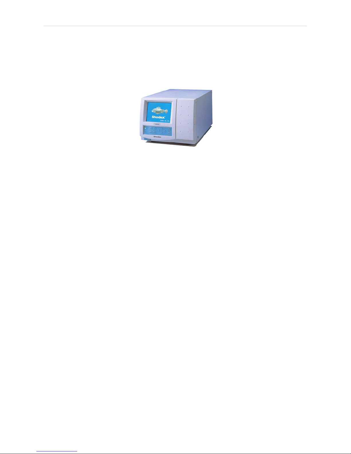
1 Shodex RI-101 Control Module
This manual describes the setting of the Shodex RI-101 , RI-102 and RI-
104 detector. The control module enables direct control of the instrument
over serial line.
Fig 1: Sh odex RI-101 detector
Direct control means that the detector can be completely controlled from
the Clarity environment. The Instrument method controlling the analysis
conditions will be saved in the measured chromatograms.
The control is performed via the UNI Ruby control module and the
Shodex RI-101 script.
- 1 -
Page 6

Shodex RI-101 2 Requirements
2 Requirements
l Clarity Installation DVD- ROM with LC Control (p/n A24) or GC Control
module (p/n A23) license.
l Free serial COM port in the PC.
Note: Modern computers usually have only one (if any) serial (COM) port
installed. To use more devices requiring the RS232 port, the MultiCOM
adapter (p/n MC01) is available.
l Serial DB9F-DB9M straight cable (p/n SK02).
Note: Cables are not part of Clarity Control Module. It is strongly
recommended that you order the required cables together with the
Control Module.
- 2 -
Page 7

Shodex RI-101 3 Installation Procedure
3 Installation Procedure
3.1 Shodex RI-101 detector communication
The Shodex RI-101 is controlled by serial (RS232) communication. It uses
a standard serial DB9F-DB9M straight cable (p/n SK02) described in the
picture below.
Fig 2: Serial DB9F-DB9M straight cable
- 3 -
Page 8

3 Installation Procedure ClarityControls
3.2 Clarity Configuration
Fig 3: How to Add Shodex RI-101 module
l
Start the Clarity station by clicking on the icon on the desktop.
l Invoke the System Configuration dialog accessible from the Clarity
window using the System - Configuration... command.
l Press the Add button (① on Fig 3 on pg 4.) to invoke the Available Control
Modules dialog.
l You can specify the search filter ② to simplify the finding of the driver.
- 4 -
Page 9

Shodex RI-101 3 Installation Procedure
l Select the correct item and press the Add (③ on Fig 3 on pg 4 .) button.
Each device with already created UNI profile should have its own item
named accordingly in the Available Control Modules dialog.
l The DataApex UNI Setup dialog will appear.
Fig 4: DataApex UNI Setup
l Set the correct communication Port and click on the AutoDetect button to
establish communication with the device.
l You may fill in the custom Device Name.
Note: The DataApex UNI Setup dialog is described in detail in the chapter
"DataApex UNI Setup" on pg 12.
l The Shodex RI-101 item ④ will appear in the Setup Control Modules list
of the System Configuration dialog.
l Drag the appropriate item from the Setup Control Modules list on the left
side to the desired Instrument tab ⑤ on the right side ⑥ , or click on the
button ⑦ .
- 5 -
Page 10

Shodex RI-101 4 Using the control module
4 Using the control module
After adding and setting up the detector a new Acquisition tab will appear
in the Method Setup dialog. A new Shodex RI-101 detector section
enabling the monitoring of the current detector state will be also created in
the Device Monitor window.
- 6 -
Page 11

4 Using the control module ClarityControls
4.1 Method Setup - Acquisition
The Method Setup - Acquisition tab serves for setting the common
parameters of the Shodex RI-101 detector. If more than one detector is
available, it is possible to select between them by using the Select
Detector combobox on the top of the dialog.
Fig 5: Method Setup - Acquisition
Sampling Period [s]
Defines the frequency of data being gathered in the detector. The
frequency of the data being sent to Clarity from the detector is defined by
Response Time parameter. Valid values for the Shodex RI-101 detector
range from 0.1 to 2.0 s.
Range for Integrator Output [µRIU/V]
Sets the output range for the Integrator Output analog output, as well as
digital signal sent to Clarity. The available range is dependent on the
Detector Model as set in the DataApex UNI Setup dialog.
Range for Recorder Output [µRIU/FS]
Sets the output range for the Recorder Output analog output, as well as
digital signal sent to Clarity.
Polarity of the Output Signals
Determines the polarity of the output signal.
Balance of the Output Signals [mV]
Defines the value to which the signal level will be reset when Autozero
function is used.
- 7 -
Page 12

Shodex RI-101 4 Using the control module
Response Time [s]
Sets the frequency of the data being sent to Clarity from the detector.
Setting this parameter to other value than Sampling Period means that the
detector will filter the data and only send averaged values to Clarity.
Temperature [°C]
Defines the working temperature of the Shodex RI-101 detector.
Equilibration Temperature Tolerance [°C]
Serves for the setting of the target temperature tolerance. When the
temperature reaches the desired value with the tolerance set here, the
detector gets to the READY state.
Autozero before Run
Sets whether the detector should be autozeroed at the beginning of the
analysis run.
From Det
Loads the detector control parameters from the detector to Clarity.
Det Status
When invoked, opens the Hardware Configuration dialog showing the
information regarding the connected detector.
- 8 -
Page 13

4 Using the control module ClarityControls
4.2 Method Setup - Advanced
The Method Setup - Advanced tab serves for setting the usage of auxiliary
signals of the Shodex RI-101 detector.
Fig 6: Method Setup - Advanced
The list of available auxiliary signals is shown in the table in the lower part
of the dialog. By checking the checkbox in the Store column for the
particular row, the given auxiliary signal will be stored into the measured
chromatogram.
- 9 -
Page 14

Shodex RI-101 4 Using the control module
4.3 Hardware Configuration
The Hardware Configuration dialog (invoked by using the Det Status
button from the Method Setup - Acquisition dialog) displays the
configuration of the Shodex RI-101, namely the communication type and
its parameters.
Fig 7: Hardware Configuration
- 10 -
Page 15

4 Using the control module ClarityControls
4.4 Device Monitor
The window with the detector status can be invoked by the Monitor Device Monitor command from the Instrument window or using the
Device Monitor icon.
Fig 8: Device Monitor - Detector
Autozero
Zeroes the connected detector.
Valve Current Position
Shows the state of the purge valve. The valve position can be changed
using the Purge Valve row.
Purge Valve
Allows to set the purge valve on or off. The current state of the Purge valve
is visible in the Valve Current Position row. Such action can only be
performed outside of the analysis run.
Current Temperature [°C]
Shows the current temperature of the detector cell.
Set Temperature [°C]
Shows the set temperature of the detector cell.
- 11 -
Page 16

Shodex RI-101 4 Using the control module
4.5 DataApex UNI Setup
The appearance of the DataApex UNI Setup dialog depends on the
presence of the selected Ruby Script - if the script is not present, only the
Ruby Script field is visible.
Fig 9: DataApex UNI Setup
Ruby Script
Displays the selected Ruby Script. The correct SHODEXRI101DET.RB
script for the Shodex RI-101 detector can be found in the UTILS/UNI_
DRIVERS/SHODEX subdirectory (accessible through the button) of
the Clarity installation folder (C:\CLARITY\BIN by default).
Port
Defines the communication port used, possible values dependent on the
type of communication of the device and/or available ports in the PC.
AutoDetect
It is used for verifying the device communication over the serial port
selected above.
Detector Name
Allows you to set the custom name of the detector. This name (entered
into the Value column) will be used throughout the Clarity station.
Detector Model
Allows you to set the type of the detector. The selection influences several
settings further in Method Setup - Acquisition dialog.
- 12 -
Page 17

Shodex RI-101 5 Report Setup
5 Report Setup
The detector section on the method report can be enabled by checking
the Instrument Control checkbox on the Method tab of the Report Setup
dialog. Auxiliary signals setting made on Method Setup - Advanced tab
will be also printed.
Fig 10: Report Setup
All of the parameters set in the Method Setup - Acquisition dialog are
reported, as well as the custom Detector Name and other parameters set
in the DataApex UNI Setup dialog.
- 13 -
Page 18

Shodex RI-101 6 Troubleshooting
6 Troubleshooting
When the solution to a problem cannot be found easily, a recording of the
communication between Clarity and the detector will significantly help
DataApex support.
The data recording can be enabled by adding or amending the
COMMDRV.INI file in the Clarity installation directory (C:\CLARITY\CFG
by default). The file can be edited in any text editor (e.g. Notepad). The
following section should be edited or added:
[COM1]
echo=on
textmode=on
filename=CommDrvCOM1_%D.txt
reset=off
Note: Instead of COM1, type the communication port used to communicate with
the Shodex RI-101 detector. This port number is displayed when the Det
Status button in the Method Setup - Acquisition dialog is invoked.
Note: %D (or %d) in the filename parameter means that the log will be created
separately for each day. The reset=off parameter disables deleting the
content of the log each time the station is started during the same day.
The created *.TXT files will be of great help in the diagnosis of not
documented errors and communication issues.
- 14 -
 Loading...