

Page 1

Clarity Controls
Shimadzu GC-201x
GC ENG
Code/Rev.: M113/70A
Date: 21.4.2016
Phone: +420 251 013 400 DataApex Ltd.
Fax: +420 251 013 401 Petrzilkova 2583/13
clarity@dataapex.com 158 00 Prague 5
www.dataapex.com The Czech Republic
Page 2

Clarity®, DataApex®and
®
are trademarks of DataApex Ltd. Microsoft®and Windows
TM
are
trademarks of Microsoft Corporation.
DataApex reserves the right to make changes to manuals without prior notice. Updated manuals can be
downloaded from www.dataapex.com.
Author: JK
Page 3

Shimadzu GC-201x Table of Contents
Contents
1 Shimadzu GC-201x Control module 1
2 Requirements 2
3 Installation Procedure 3
3.1 Hardware - Wiring 3
3.2 Shimadzu GC-201x setup - communication 3
3.3 Clarity Configuration 4
4 Using the control module 7
4.1 Hardware Configuration 7
4.2 Method Setup - GC 8
4.2.1 Method Setup - GC - Oven/Zones 8
4.2.2 Method Setup - GC - FLOW 1(2) 9
4.2.3 Method Setup - GC - DET 1 (..4) 12
4.2.4 Method Setup - GC - Time Events 15
4.2.5 Method Setup - GC - Pre Run 17
4.2.6 Method Setup - GC - APC 18
4.2.7 Method Setup - GC - AMC 19
4.2.8 Method Setup - GC - Other 20
4.2.9 Method Setup - GC - Gradients 21
4.3 Method Setup - Acquisition 22
4.4 Device Monitor 23
4.5 Shimadzu GC-201x Setup 24
5 Report Setup 30
6 Troubleshooting 31
- i -
Page 4

Table of Contents Clarity Controls
To facilitate the orientation in the Shimadzu GC- 201x manual and Clarity chromatography
station, different fonts are used throughout the manual. Meanings of these fonts are:
Instrument (blue text) marks the name of the window to which the text refers.
OpenFile (italics) describesthe commands and names of fields in Clarity, parameters that can
be entered into them or a window or dialog name (when you already are in the topic describing
the window).
WORK1 (capitals) indicates the name of the file and/or directory.
ACTIVE (capital italics) marks the state of the station or its part.
The bold text is sometimes also used for important parts of the text and the name of the Clarity
station. Moreover, some sections are written in format other than normal text. These sections are
formatted as follows:
Note: Notifies the reader of relevant information.
Caution: Warns the user of possibly dangerous or very important
information.
▌ Marks the problem statement or trouble question.
Description: Presents more detailed information on the problem, describes its causes,
etc.
Solution: Marks the response to the question, presents a procedure how to remove it.
- ii -
Page 5
Shimadzu GC-201x 1 Shimadzu GC-201x Control module
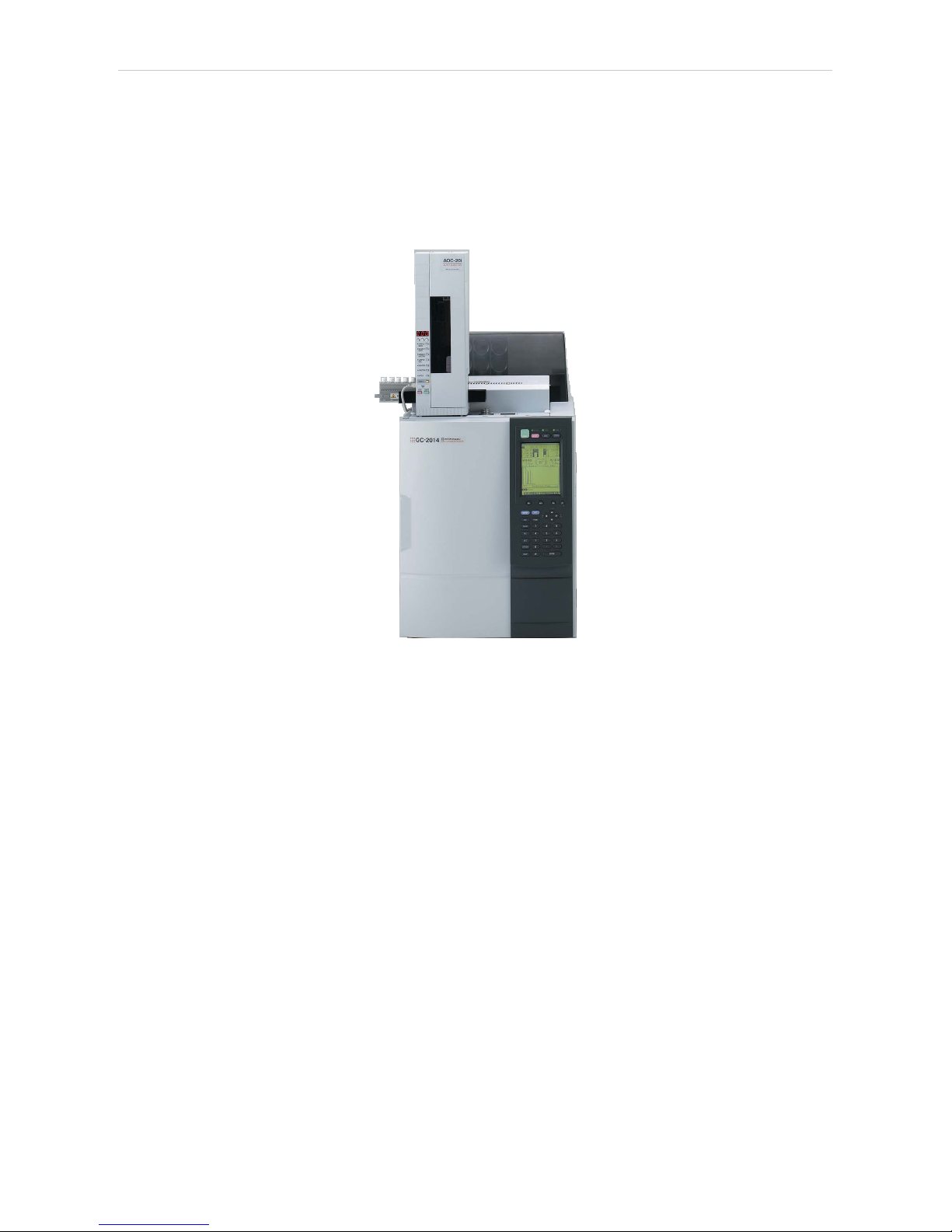
1 Shimadzu GC-201x Control module
This manual describes the setting of the Shimadzu GC- 201x control
module. The control module enables direct control of chromatographs of
Shimadzu GC2010, GC2014 , GC2014C and GC2014 APC/AFC types
over serial line.
Fig 1: Shimadzu GC-2014C (with AOC-20i autosampler)
- 1 -
Page 6

Shimadzu GC-201x 2 Requirements
2 Requirements
l Clarity Installation CD ROM with GC Control module (p/n A23).
l Free serial COM port in the PC.
Note: Modern computers usually have only 1 (if any) serial (COM) port installed.
To use more devices requiring the RS232 port, the MultiCOM adapter
(p/n MC01) is available.
Caution: Models 2014C and 2014C AFC/APC require manual setup.
l Serial cross DB9F-DB9F cable (p/n SK01).
Note: Cables are not part of Clarity Control Module. It is strongly
recommended to order required cables together with the Control Module.
- 2 -
Page 7
Shimadzu GC-201x 3 Installation Procedure
3 Installation Procedure
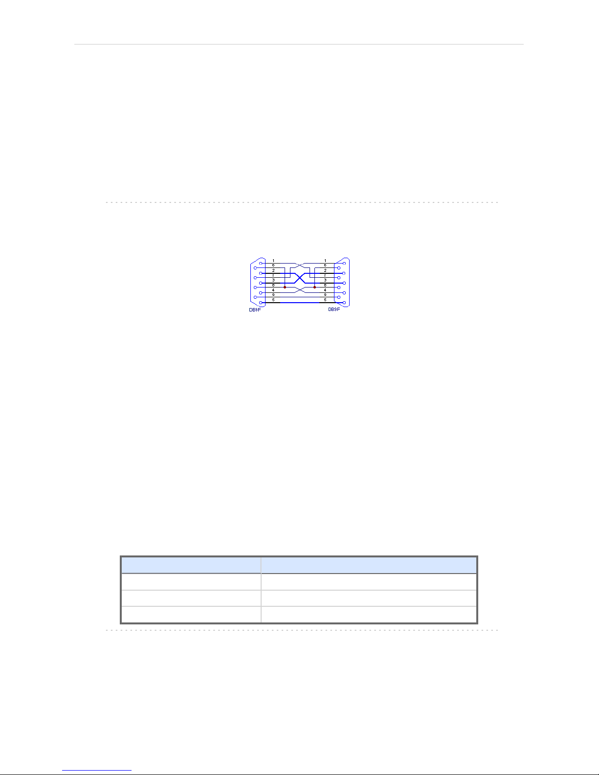
3.1 Hardware - Wiring
Start and Ready signals are communicated with Clarity through the Serial
cross DB9F- DB9F cable, so it is not necessary to connect additional
starting cables. The signal cable has to be connected according to the
following scheme.
In a set with the Autosampler synchronization cables might be necessary.
Note: Typicalconnections of a set with Autosampler can be found in the Getting
Started manual (chapter Device Setup and Wiring).
Typical serial cable wiring is described in the picture.
Fig 2: Serial cross cable DB9F - DB9F
3.2 Shimadzu GC-201x setup - communication
The GC must be fully configured prior to connecting to Clarity. No special
settings have to be made on the Shimadzu GC-201x chromatograph, only
the communication protocol of the instrument (set on the FUNC key
screen by using 6. GC CONFIGURATION - 3. TRANSMISSION
PARAMETER) has to be set to LEVEL3 . Baud rate set in the instrument
must correspond to the Baud Rate set in the Shimadzu GC-201x Setup
dialog. For locally connected instruments with short interconnecting cable
the Baud Rate set as default (115200 ) is recommended. With the rising
length of the cable or when connected via the network the Baud Rate
should be set lower. Maximum Baud Rate depends on the length of cable
and its capacitance. For standard type of cable recommended maximum
Baud Rate is following:
Length of the cable Maximum recommended speed
3 m 115200 bps
6 m 57600 bps
15 m 19200 bps
Note: When controlling Shimadzu AOC20 autosampler, a separate serial line
is required, connecting the autosampler directly to PC.
- 3 -
Page 8
3 Installation Procedure ClarityControls
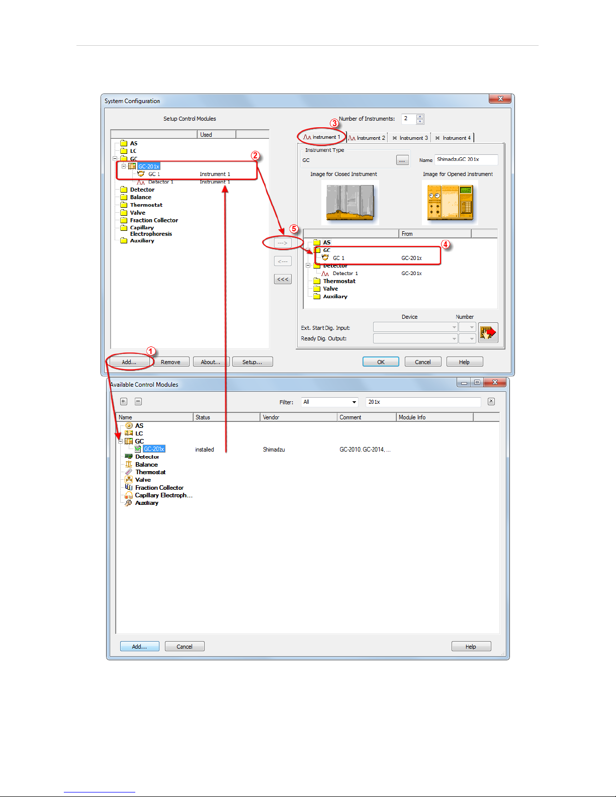
3.3 Clarity Configuration
Fig 3: System Configuration
- 4 -
Page 9
Shimadzu GC-201x 3 Installation Procedure
l In the System Configuration dialog press the Add button ① to invoke the
Available Control Modules dialog.
l Select the Shimadzu GC- 201x in the GC section and press the Add
button.
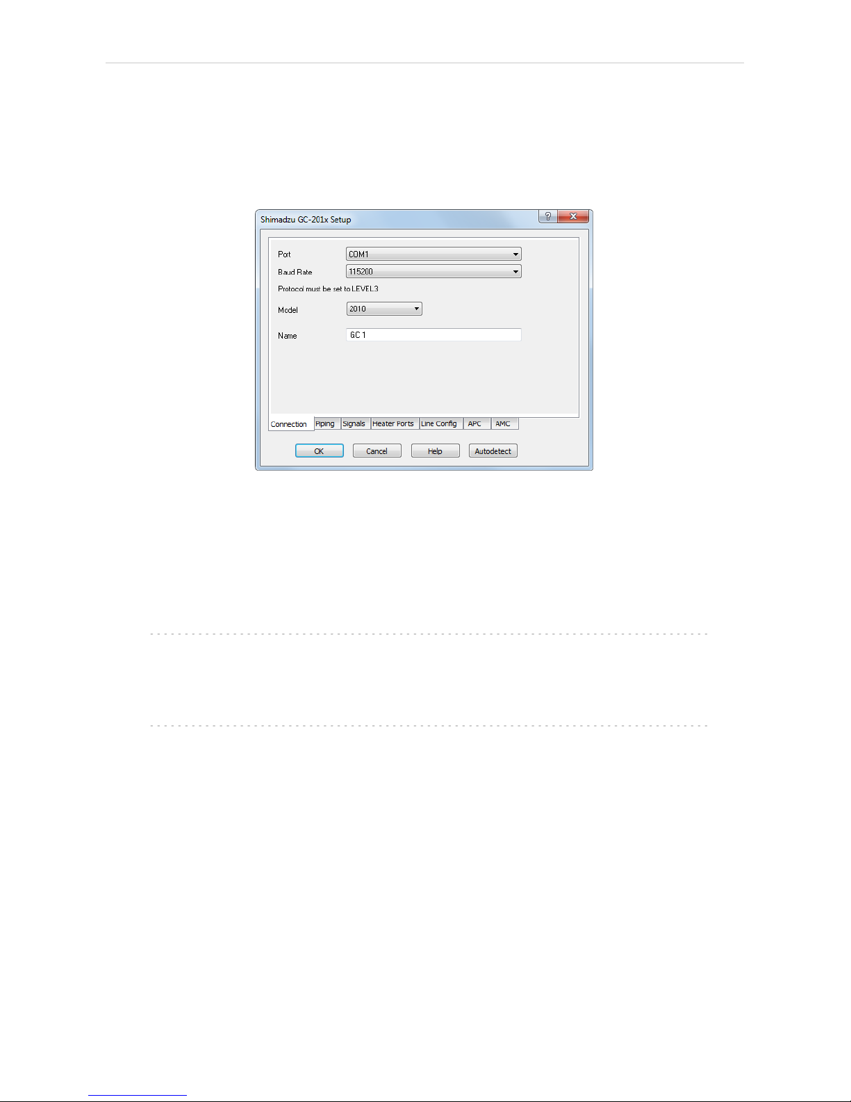
l The Shimadzu GC-201x Setup dialog will appear.
Fig 4: Shimadzu GC-201x Setup
l Fill in the Port, Baud Rate and Name according to the settings and the
connection of the GC (for more details see the chapter Shimadzu GC201x Setup on pg 24)..
l Press the Autodetect button to read all settings from the instrument and
apply them in the Shimadzu GC-201x Setup dialog.
Note: It is strongly recommended not to change the settings gained through the
Autodetect function. When opening the Instrument window, those
settings are checked against the settings of the GC and in case they are
not the same the warning message is issued and no control is possible.
Note: Only GC2010 and GC2014 models are autodetected properly. When
using GC2014C or GC2014 APC/AFC , the exact type used needs to be
selected after autodetection.
l Switch to the Signals tab (for more details see the Shimadzu GC- 201x
Setup dialog section later in the manual), select the correct number of
signals you want to acquire, name them and possibly check the This
Device Starts the Run in Clarity / Clarity Starts This Device radiobutton.
The Clarity Starts This Device option should be checked only when the
GC will not start the acquisition (that means it will not be triggered by the
GC Start button, external start contact or autosampler). Press the OK
button.
- 5 -
Page 10

3 Installation Procedure ClarityControls
l The Shimadzu GC-201x item ② will appear in the Setup Control Modules
list of the System Configuration dialog.
l Drag the GC icon from the Setup Control Modules list on the left side to
the desired Instrument tab ③ on the right side ④ , or use the button ⑤
to do so.
- 6 -
Page 11
Shimadzu GC-201x 4 Using the control module
4 Using the control module
New GC tab appears in the Method Setup dialog, enabling the setting of
the GC control method.
From GC
Reads the actual values from the GC and loads them into the method.
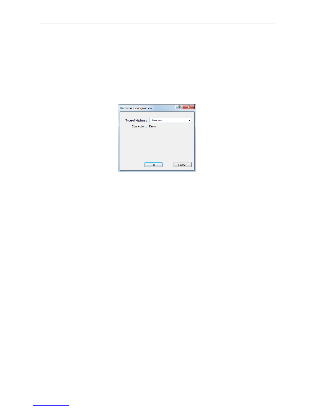
4.1 Hardware Configuration
Fig 5: Hardware Configuration
This dialog is invoked by pressing the GC Status button in the Method
Setup - GC dialog. Hardware Configuration dialog displays the type of the
chromatograph and the COM port to which it is connected.
- 7 -
Page 12

4 Using the control module Clarity Controls
4.2 Method Setup - GC
4.2.1 Method Setup - GC - Oven/Zones
Fig 6: Method Setup - GC - Oven/Zones
Oven Max
Sets the maximal allowed temperature for the column oven. Possible
values are: 0 - 470.
Note: Please note that the maximum value may differ for certain GC models -
listed values for it range between 350 and 470 °C.
Equilibration Time
Time that the GC needs to reach the temperature equilibrium after the
temperature program gets to the set initial temperature. This time is used
to distribute the heat evenly in the oven.
Gradient Table
Sets the Heat Rate, desired temperature ( Final Temp ) and time to hold
this temperature (Hold Time). The Total Time column will be calculated
automatically. In other words, for isothermal part of the temperature
gradient, the temperature set in Final Temp will be kept for the interval set
in Hold Time. To delete a row, simply delete the value in the Heat Rate
column on that row.
Temperature Zones
Sets the temperature and maximum temperature of the zones that have
been set in the Shimadzu GC-201x Setup - Heater Ports dialog (for more
details see also chapter Shimadzu GC-201x Setup on pg 24).
- 8 -
Page 13

Shimadzu GC-201x 4 Using the control module
Description
Description of the method (this description is not sent to or read from GC, it
serves for the information purposes only).
4.2.2 Method Setup - GC - FLOW 1(2)
Fig 7: Method Setup - GC - FLOW 1
This tab governs the settings concerning the injection port of the
Shimadzu GC- 201x chromatograph. Up to two injection ports may be
configured and used at the same time. The tab is only present when some
inlet is configured in the Shimadzu GC-201x Setup - Piping dialog for a
given injector port. The fields dealing with flow of gases are available only
for models of chromatograph equipped with Advanced Flow Control
(AFC). These are GC2010, GC2014 and GC2014 APC/AFC.
On/Off
Turns on/off the inlet.
Split Mode
Defines the operation mode for the injector port. The possible options are
Split, Splitless and Direct (see Shimadzu GC-201x hardware manual for
more details on these injection modes). Available for SPL inlet only.
Control Mode
Sets the mode of operation of the dual- packed injector - this injector may
work in the Dual, Single Land Single R modes. When Single L or Single R
is selected either on the Flow 1 or Flow 2 tab, commands located on Flow
3 tab are automatically disabled from altering.
Sampling Time [min.]
Sets the sampling time in minutes for the Splitless Sampling Mode.
- 9 -
Page 14

4 Using the control module Clarity Controls
Column i.d.
Sets the inner diameter of the column.
Column length
Sets the length of the column.
Film thickness
Sets the thickness of the column inner coating.
Flow Control Mode
Selects the flow control mode for the inlet.
Inlet Pressure
Sets the gas pressure for the inlet.
Column Flow
Sets the flow for the inlet.
Linear Velocity
Sets the linear velocity of gas for the inlet. This value is linked with two
preceding values ( Inlet Pressure and Column Flow ) by mutual
recalculation performed by chromatograph itself. Thus it is possible to
enter only one of them, the others will be calculated by chromatograph
and can be downloaded using From GC button.
Split Ratio
Sets the split ratio for split operation. Available for SPL inlet only.
Total Flow
Sets the total flow for the inlet.
Carrier Gas
Sets the type of gas used as the carrier.
Purge Flow
Sets the purge flow for the inlet. Available for SPL inlet only.
- 10 -
Page 15

Shimadzu GC-201x 4 Using the control module
Program …
Opens the dialog for setting the pressure/flow program. The tables allows
to set the pressure/flow program for the analysis and for purging the inlet.
Fig 8: Method Setup - GC - FLOW 1 - Program
Advanced …
Opens the dialog for setting the advanced parameters of the inlet - split
time program, high- pressure injection parameters, carrier gas saver
program and splitter hold parameter.
Fig 9: Method Setup - GC - FLOW 1 - Advanced
- 11 -
Page 16

4 Using the control module Clarity Controls
4.2.3 Method Setup - GC - DET 1 (..4)
Fig 10: Method Setup - GC - DET 1
This tab allows to set the parameters for a detector configured in the
Shimadzu GC- 201x Setup dialog. Particular fields may vary, according to
the type of the detector set. The fields dealing with flow of gases are
available only for models of chromatograph equipped with Advanced
Pressure Control (APC). These are GC2010 and GC2014 APC/AFC.
On/Off
Switches the detector on and off. The detector switched off gives 0 as a
resulting signal.
Filter Time Const.
The value set here influences the processing of the detector signal. It
works as a noise filter, the higher the constant, the lower the noise. On the
other hand, usage of the higher values will flatten peaks and may cause
lower or smaller peaks to disappear.
Control Mode
Sets the mode of operation of the particular detector. Two option sets are
available in this field, depending on the type of the detector used:
l Dual flame ionization detector (WDFID) may work in the Dual mode or use
the signal from one cell only. Dual detector can also measure only on
single cell - then select Single L for the left cell or Single R for the right
cell.
l Flame thermionic detector (FTD and WFTD) allows to use two possible
control modes - Current and Voltage.
- 12 -
Page 17

Shimadzu GC-201x 4 Using the control module
Signal Polarity
This field is only present when using the dual detector in the Dual mode or
one of TCD detectors. Sets the polarity of the dual data, or in other words,
the method of data calculating (either the signal of the right cell minus the
signal of the left cell (polarity -) or vice versa (polarity +)). Available for
TCD and WDFID detector only.
Range
Applies on the detector signal before its processing to the analog output in
the Shimadzu GC-201x. This value serves for the compensation of the
overly high signals.
Current
Serves for entering the value of current set on the detector. Possible range
and units depend on the type of the detector - FTD detector has the range
of values 0.00-10.00 pA, ECD detector 0.00- 2.00 nA and TCD detector 0-
200 mA. This field is only present for Electron capture (ECD), Thermal
conductivity (TCD) and Flame thermoionic (FTD and WFTD) detectors.
Signal Output Port
Specifies the signal output of the particular detector. Shimadzu GC-201x
provides up to 4 signal outputs set in the Shimadzu GC- 201x Setup -
Signals dialog
Power Controller
This field is only present on tabs of Flame thermoionic detectors (FTD and
WFTD).
- 13 -
Page 18

4 Using the control module Clarity Controls
Adjust Time
This field can only be edited when the Power Controller checkbox is
selected.
Interference Filter
Possible values are P, S and Sn. This field is only present when using the
Flame photometric detector (FPD or WFPD).
Signal Type
Sets the type of the signal - Wide or Linear. The selection influences the
possible values present in the Range field.
H2 Flow
Turns On/Off the flow of hydrogen and sets its value. Available for FID,
WFID, WDFID, FPD, WFPD, SID, WSID, FTD and WFTD detector.
Make Up
Turns On/Off the flow of make-up gas and sets its value and type of the
gas. Available for FID, WFID, WDFID, FPD, WFPD, SID, WSID, FTD and
WFTD detector.
Air Flow
Turns On/Off the flow of the air and sets its value. Available for FID, WFID,
WDFID, FPD, WFPD, SID, WSID, FTD and WFTD detector.
Program …
Opens the dialog for setting the flow program. The tables allows to set the
flow program for the detector during the analysis. Available for FID, WFID,
WDFID, FPD, WFPD, SID, WSID, FTD and WFTD detector.
Fig 11: Method Setup - GC - DET1 - Program
- 14 -
Page 19

Shimadzu GC-201x 4 Using the control module
4.2.4 Method Setup - GC - Time Events
Fig 12: Method Setup - GC - Time Events
This tab allows to set the events that should happen during the run based
on the analysis time. This includes events like switching the detector
polarity, range or current (where applicable), setting temperatures to
detector/injector/auxiliary zones etc. To delete a row, simply delete the
value in the Time column on that row.
Note: This tab uses the same functions as the Pre Run tab, so these are
described together.
The table should be filled with the Time of the event in the first column (in
minutes, decimal format - 2 minutes 45 seconds should be set as 2.75),
the event type in the Event column, event value in the Value column and
the Line selected as set on the Shimadzu GC- 201x Setup - Line Config
tab. Possible events are:
Det 1(..4) Polarity
Sets the polarity of the detector (if the polarity for the given detector has
any sense). Polarity + corresponds to the value 1, polarity - corresponds to
the value 2.
Det 1(..4) Range
Changes the detector range (as set before the analysis on the DET X tab)
during the course of the analysis. Range x1 corresponds to value 0, range
x10-1to value 1, x10-2to value 2, x10-3to value 3 and x10-4to value 4.
- 15 -
Page 20

4 Using the control module Clarity Controls
Det 1(..4) Current
Changes the current value of the detector (if the current for the given
detector has any sense). The new value should be in range and units
dependent on the type of the detector - FTD detector has the range of
values 0.00-10.00 pA , ECD detector 0.00-2.00 nA and TCD detector 0-
200 mA.
Note: All 4 possible detectors are listed, even if they are not present and
configured in the Shimadzu GC-201x Setup dialog. Those not configured
will have the text in the format Det #X Polarity etc. with the # character -
these shouldn't be used in the Time Events table.
Event Operation
Performs an event operation defined by the event code. These codes may
be used as a positive number or negative number, in which case the
opposite of the operation is performed. For example, event code 51
performs the autozero operation on detector 1, while - 51 event code
cancels the zero adjustment on detector 1. The basic event codes and
their functions are:
Tab 1: Event codes
Event Code Function
51 Autozeroes the Detector 1
52 Autozeroes the Detector 2
53 Autozeroes the Detector 3
54 Autozeroes the Detector 4
Note: For more event codes please see Shimadzu hardware documentation.
Temperature of INJ1(2), DET1(2), AUX3(..5)
Changes the temperature of the particular temperature zone. The initial
temperature is set on the Oven/Zones tab, but can be changed later
during the analysis this way. The Value column should hold the
temperature in °C.
Program stop
Stops the GC control program. The value entered into the Value column
should be set to XY, where X is the number of runs before the program
stop command is sent and Y is the number of file (in the GC) to be loaded
after that. For example value 16 corresponds to the program stop
command sent after one run of the method, after which the FILE6 is
loaded. The number of method runs doesn't have any meaning for Clarity
as the method is usually sent after each injection, thus resetting the
counter after each injection. For more details, consult Shimadzu manual.
- 16 -
Page 21

Shimadzu GC-201x 4 Using the control module
4.2.5 Method Setup - GC - Pre Run
Fig 13: Method Setup - GC - Pre Run
This tab has the same functionality as the Time Events tab, so the
functions are described there together. The Pre Run tab serves for setting
of the program that takes place before the analysis start.
- 17 -
Page 22

4 Using the control module Clarity Controls
4.2.6 Method Setup - GC - APC
Fig 14: Method Setup - GC - APC
This tab allows you to set the parameters of your Auxiliary Pressure
Control device.
Mode
Allows you to choose between Pressure and Flow modes.
Gas
Select the type of gas.
Pneumatic Resistance
Set the pneumatic resistance of the column.
Initial Pressure [kPa]
Set the initial pressure of the gas in kPa.
- 18 -
Page 23

Shimadzu GC-201x 4 Using the control module
4.2.7 Method Setup - GC - AMC
Fig 15: Method Setup - GC - AMC
This tab allows you to set the parameters of your Auxiliary Media Control
device.
Gas
Select the type of gas.
Initial Flow [mL/min.]
Set the initial flow of the gas in mL/min.
- 19 -
Page 24

4 Using the control module Clarity Controls
4.2.8 Method Setup - GC - Other
Fig 16: Method Setup - GC - Other
This tab allows to set the behavior of some parts of the Shimadzu GC201x chromatograph.
Shutdown
Defines the behavior of the chromatograph after the analysis end.
Keep State
The chromatograph will do nothing when the analysis is completed.
Set Off after analysis
The chromatograph performs the System Off function (check
Shimadzu GC-201x manual for more details). This function is useful
for switching the chromatograph off after the last sample in the
sequence. When the Clarity Instrument is set to send a method
without prompting in the System Configuration - Instrument Method
Sending dialog and there is another method opened in the Instrument
window at the analysis end, the chromatograph will be turned off by
the current method and then turned on by the sending of the
instrument method.
Caution: Be careful when switching off instruments without automatic pressure
control and automatic flow control - the manually controlled gases flow is
not switched off, which may end in the leakage of possibly dangerous
gases (hydrogen) into the laboratory environment.
- 20 -
Page 25

Shimadzu GC-201x 4 Using the control module
Zero at ready
When checked, the chromatograph performs the autozero action after it
becomes READY.
Auto flame ON
When checked, the chromatograph will try to ignite the flame in the
detector after sufficient temperature and gasses pressure was reached.
Re-ignite
While checked, the chromatograph will try to re-ignite the flame in the
detector when it is quenched. This may be important during the start of the
chromatograph as the auto ignition may not be successful on the first try.
4.2.9 Method Setup - GC - Gradients
Fig 17: Method Setup - GC - Gradients
This tab displays the temperature gradient as set on the Method Setup -
GC - Oven/Zones tab.
- 21 -
Page 26

4 Using the control module Clarity Controls
4.3 Method Setup - Acquisition
Fig 18: Method Setup - Acquisition
Each detector allows to set the particular Sampling Rate on the
appropriate tab. This sampling rate in fact states the frequency of the data
sending from the Shimadzu GC-201x detector to Clarity, it has nothing to
do with the frequency of actual data acquisition in the instrument. To
switch to another detector, use the Select Detector field on the top of the
Method Setup - Acquisition dialog.
- 22 -
Page 27

Shimadzu GC-201x 4 Using the control module
4.4 Device Monitor
Fig 19: Shimadzu GC-201x Device Monitor
The Monitor window for the Shimadzu GC-201x chromatograph displays
all set and actual temperatures in each temperature zone and the column
oven. Besides that, it also shows the run time of the analysis.
System On
Allows to switch the chromatograph on. It starts the temperature program
in the column oven, detectors and injectors.
System Off
Switches the Shimadzu GC-201x off by switching off the oven thermostat
and injector/detector heating.
Ignite
When this button is used, the chromatograph will try to ignite the flame in
the detector. The status of the flame is visible in the Detectors section of
the Monitor window (Flame row).
- 23 -
Page 28

4 Using the control module Clarity Controls
4.5 Shimadzu GC-201x Setup
Dialog tabs: Connection - Piping - Signals - Heater Ports - Line Config
Shimadzu GC- 201x Setup dialog (accessible through the System
Configuration dialog) allows to view and manually set the hardware
configuration of the chromatograph. All fields (with the exception of Name
field and the Signals tab) can be read from the chromatograph by using
the Autodetect button.
Caution: It is highly recommended not to change any data read from the
chromatograph by the Autodetect function, because these settings are
checked against those in the GC when opening the Instrument window. If
they don't match, the control is not possible. The only parts of the dialog
that can be modified without risk is the Name parameter on the
Connection tab and any data on the Signalstab.
Connection tab
Fig 20: Shimadzu GC-201x Setup - Connection
Main page of the Shimadzu GC-201x Setup dialog.
Port
Selects the COM port to which the Shimadzu GC-201x chromatograph is
connected.
Baud Rate
Sets the baud rate of the communication. For a chromatograph directly
connected to the PC via short cable it is recommended to set the Baud
Rate to 115200, for the chromatograph connected by long serial cable or
through LAN it will be necessary to set the Baud Rate lower. Default value
is 115200.
Caution: The baud rate set in this dialog must correspond to the baud rate value set
in the chromatograph.
- 24 -
Page 29

Shimadzu GC-201x 4 Using the control module
Model
Selects the exact type of instrument.
Name
Specifies the name of the chromatograph.
Autodetect
Reads the hardware configuration from the Shimadzu GC- 201x
chromatograph and sets it to the Shimadzu GC-201x Setup dialog.
Piping tab
Fig 21: Shimadzu GC-201x Setup - Piping
Car 1 (..3)
Allows to set the possible operation modes for carrier gasses. For
Shimadzu GC- 201x chromatographs (without automatic flow control
function), only the SPLITTER and PACKED options will be used, others
are saved for instruments equipped with AFC control.
Inj 1 (2)
Lists the type of the injector(s) installed.
Det 1 (..4)
Lists all detectors and other signal sources (e.g. temperature of the
measuring cell) from which the signals will be transferred into Clarity .
Each Det X field with any type of detector other than None will have its
own sub- tab with options relevant to the detector type selected in the
Method Setup - GC dialog.
- 25 -
Page 30

4 Using the control module Clarity Controls
Signals tab
Fig 22: Shimadzu GC-201x Setup - Signals
Shimadzu GC-201x Setup - Signals tab defines the number of signals that
will be processed by Clarity. These signals will be assigned to particular
detectors (hardware) in the Method Setup - GC - DET X dialog.
Count
Defines the number of signals that will be transferred to the Clarity. These
signals correspond to Clarity detectors and will have their own sub- tabs
in the Method Setup - Acquisition dialog, if configured on the given Clarity
Instrument.
Ch1(..4)
Sets the name of the particular signal.
This Device Starts the Run in Clarity / Clarity Starts This Device
This radiobutton enables to start the analysis run from the Clarity. With
This Device Starts the Run in Clarity checked, the device is started prior to
Clarity by its front button or autosampler connected to this device and
passes the start to Clarity. When Clarity Starts This Device is checked,
Clarity is started prior to this device by separately wired autosampler,
Start button in Single Run or different device and then starts this device.
Note: The This Device Starts the Run in Clarity option is checked by default.
- 26 -
Page 31

Shimadzu GC-201x 4 Using the control module
Heater Ports tab
Fig 23: Shimadzu GC-201x Setup - Heater Ports
This tab specifies the presence of individual components of the Shimadzu
GC-201x chromatograph and displays their exact position. These settings
can all be read from the instrument by using the Autodetect button.
Ports
Shows the default names of particular temperature zones as set in the
Shimadzu GC-201x chromatograph.
Names
Allows to set desired names for particular temperature zones. By default,
these names are the same as shown in the Ports column.
Type
Sets the type of the device installed in the particular temperature zone.
Position
Defines the location where the particular compartment is installed on the
Shimadzu GC-201x chromatograph. Numbers and positions of particular
locations are listed in the instruction manual of the chromatograph.
- 27 -
Page 32

4 Using the control module Clarity Controls
Line Config tab
Fig 24: Shimadzu GC-201x Setup - Line Config
This tab shows the position of particular components on the analytical
lines in the chromatograph. Up to four independent lines may be
configured. All settings on this tab may be read from the chromatograph
by using the Autodetect button.
Fig 25: Shimadzu GC-201x Setup - APC
This tab shows the presence of Auxiliary Pressure Control devices. State
of all checkboxes are autodetected, it is strongly recommended not to
change them manually.
- 28 -
Page 33

Shimadzu GC-201x 4 Using the control module
Fig 26: Shimadzu GC-201x Setup - AMC
This tab shows the presence of Auxiliary Media Control devices. State of
all checkboxes are autodetected, it is strongly recommended not to
change them manually.
- 29 -
Page 34

Shimadzu GC-201x 5 Report Setup
5 Report Setup
Fig 27: Shimadzu GC-201x report preview
All chromatograph- specific settings (e.g. temperatures set to particular
temperature zones) are reported as a part of the data displayed by the use
of Instrument Control checkbox of the Report Setup - Method dialog.
- 30 -
Page 35

Shimadzu GC-201x 6 Troubleshooting
6 Troubleshooting
When the remedy for some problem cannot be discovered easily, the
recording of communication between Clarity and the chromatograph can
significantly help the DataApex support to discover the cause of the
problem.
The recording can be enabled by adding or amending the COMMDRV.INI
file in the Clarity installation directory ( C:\CLARITY\CFG by default). The
file can be edited in any text editor (e.g. Notepad). Following section
should be edited or added:
[COM1]
echo=on
textmode=on
filename=ShimadzuGC201x.txt; %D or %d could be used to include a
current date (recommended in combination with the Reset=Off option
reset=off
Note: Instead of COM1 type the correct serial port used to communicate with
the Shimadzu GC-201x chromatograph. This port number is displayed
when the GC Status button in the Method Setup - GC dialog is invoked or
in the Shimadzu GC-201x Setup dialog.
The created *.TXT files will greatly help in diagnosis of unrecognized
errors and problems in communication.
- 31 -
 Loading...