

Page 1

Clarity Controls
Agilent 7890
GC ENG
Code/Rev.: M144/70B
Date: 1/10/2017
Phone: +420 251 013 400 DataApex Ltd.
Fax: +420 251 013 401 Petrzilkova 2583/13
clarity@dataapex.com 158 00 Prague 5
www.dataapex.com The Czech Republic
Page 2

Clarity®, DataApex®and
®
are trademarks of DataApex Ltd. Microsoft®and Windows
TM
are
trademarks of Microsoft Corporation.
DataApex reserves the right to make changes to manuals without prior notice. Updated manuals can be
downloaded from www.dataapex.com.
Author: MP
Page 3

Agilent 7890 Table of Contents
Contents
1 Agilent 7890 Control module 1
1.1 General Conditions of Agilent Autosampler Control 1
2 Requirements 3
3 Installation Procedure 4
3.1 Agilent 7890 Setup - Communication 4
3.2 Clarity Configuration 5
4 Using the control module 8
4.1 Hardware Configuration 8
4.2 Method Setup - Autosampler 9
4.3 Method Setup - GC 11
4.3.1 Oven/Zones 11
4.3.2 Front (Back) Inlet 13
4.3.3 Column # 15
4.3.4 Front (Back) Detector 17
4.3.5 Time Table 19
4.3.6 PCM 20
4.3.7 Gradients 22
4.4 Method Setup - Acquisition 23
4.5 Method Setup - Valves 25
4.6 Using Dual Injector 26
4.7 Device Monitor 27
4.8 Agilent 7890 Setup 28
4.8.1 Connection tab 28
4.8.2 GC tab 29
4.8.3 Signals tab 30
4.8.4 Sampler tab 31
4.8.5 Valves tab 32
4.8.6 Aux tab 32
4.8.7 PCM tab 33
5 Report Setup 34
6 Troubleshooting 35
- i -
Page 4

Table of Contents Clarity Controls
To facilitate the orientation in the Agilent 7890 manual and Clarity chromatography station,
different fonts are used throughout the manual. Meanings of these fonts are:
Instrument (blue text) marks the name of the window to which the text refers.
Open File(italics) describes the commands and names of fields in Clarity, parameters that can
be entered into them or a window or dialog name (when you already are in the topic describing
the window).
WORK1 (capitals) indicates the name of the file and/or directory.
ACTIVE (capital italics) marks the state of the station or its part.
The bold text is sometimes also used for important parts of the text and the name of the Clarity
station. Moreover, some sections are written in format other than normal text. These sections are
formatted as follows:
Note: Notifies the reader of relevant information.
Caution: Warns the user of possibly dangerous or very important
information.
▌ Marks the problem statement or trouble question.
Description: Presents more detailed information on the problem, describes its causes,
etc.
Solution: Marks the response to the question, presents a procedure how to remove it.
- ii -
Page 5
Agilent 7890 1 Agilent 7890 Control module
1 Agilent 7890 Control module
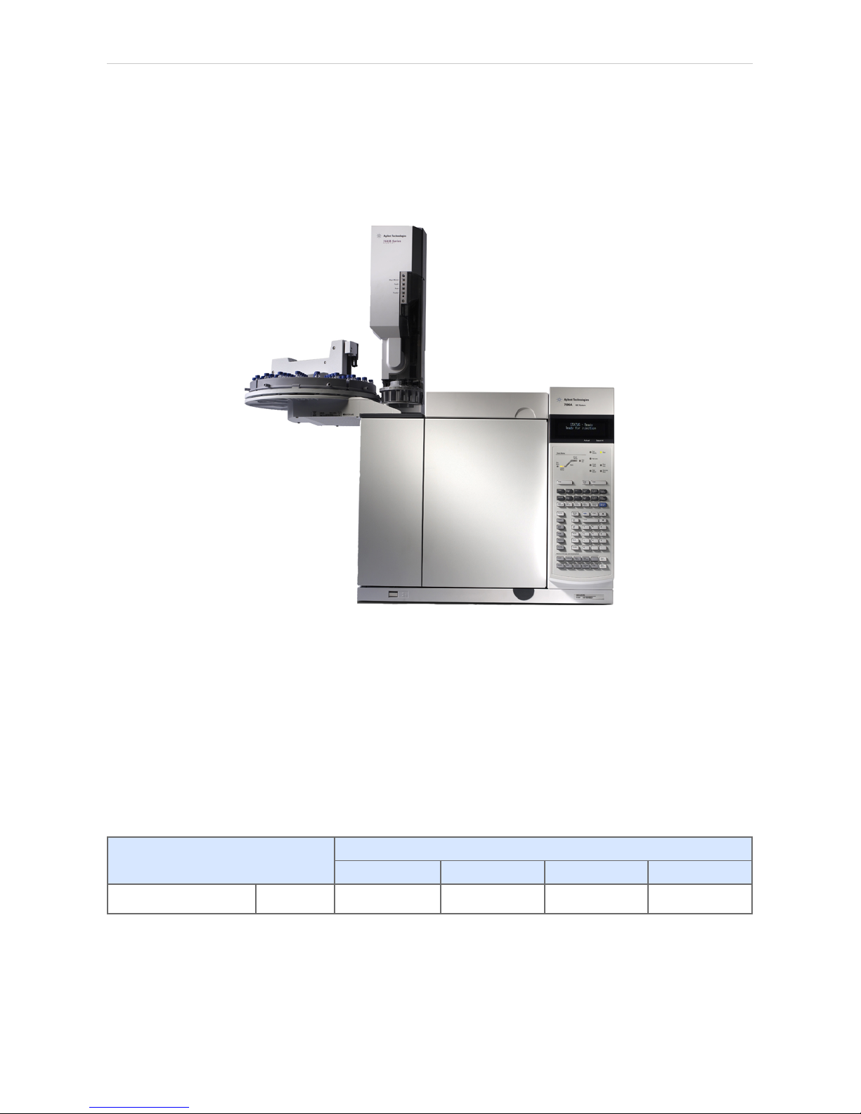
This manual describes the setting of the Agilent 7890 chromatograph
control module. Supported versions of the chromatograph are 7890A and
7890B. The control module enables direct control of the instrument over
Local Area Network (LAN).
Fig 1: Agilent 7890A Gas Chromatograph (with 7683 autosampler)
1.1 General Conditions of Agilent Autosampler Control
Clarity allows controlling all Agilent GC autosamplers and for their control
is always required to purchase AS Control Module (p/n A26) license. Not
all combinations of autosamplers and 7890 GCs are possible. To find out
if desired combination of autosampler and 7890 GC is available refer to
following table.
Tab 1: Possible combinations of Agilent autosamplers and Agilent gas chromatographs:
Autosamplers
7673 (A, B, II) 7683 7693 6850
Chromatograph 7890
û ü ü û
The autosampler 7683 (or 7693) is connected to GC via Agilent
proprietary connection and its hardware configuration is described in the
section Sampler tab on pg 31 because the autosampler control is
implemented through DataApex 7980 Control Module.
- 1 -
Page 6

1 Agilent 7890 Control module Clarity Controls
There is a Dual Injection mode support implemented for 7890 GCs. In
case of 7890 CGs Dual Injection hardware configuration is described in
the section Sampler tab on pg 31 because the autosampler control is
implemented through DataApex 7890 Control Module.
- 2 -
Page 7

Agilent 7890 2 Requirements
2 Requirements
l Clarity Installation CD ROM with GC Control module (p/n A23).
Caution: Minimal firmware version required for 7890A and 7890B is A.01.10.0.
l LAN card in the PC.
l Cross LAN cable (p/n SK08).
Note: Cables are not part of Clarity Control Module. It is strongly
recommended to order required cables together with the Control Module.
- 3 -
Page 8

Agilent 7890 3 Installation Procedure
3 Installation Procedure
3.1 Agilent 7890 Setup - Communication
The GC must be fully configured prior to connecting to Clarity. No special
settings have to be made on the Agilent 7890 chromatograph, only the
correct IP address of the instrument (set on the OPTIONS key screen by
using COMMUNICATION - IP item). A default IP address of most Agilent
GC's is 10.1.1.101 which is suitable only in case the GC is connected
directly to computer using separate network.
Caution: Do not use the Agilent 7890 DHCP server feature.
When using the LAN communication it is recommended to attach the GC
chromatograph directly to the PC avoiding hubs, switches etc. Contact
your local LAN administrator who can make the appropriate settings.
In case your network uses firewall for protection, make sure that
connection is not blocked in both directions. (chromatograph uses
separate connection for control communication and for data sending).
Caution: Cross LAN cable is primarily used for the direct connection of the
chromatograph and the PC. This cable can also be used for the
connection of the device to the switch or network socket, but with older
switches, the straight LAN cable might be necessary.
- 4 -
Page 9
3 Installation Procedure Clarity Controls
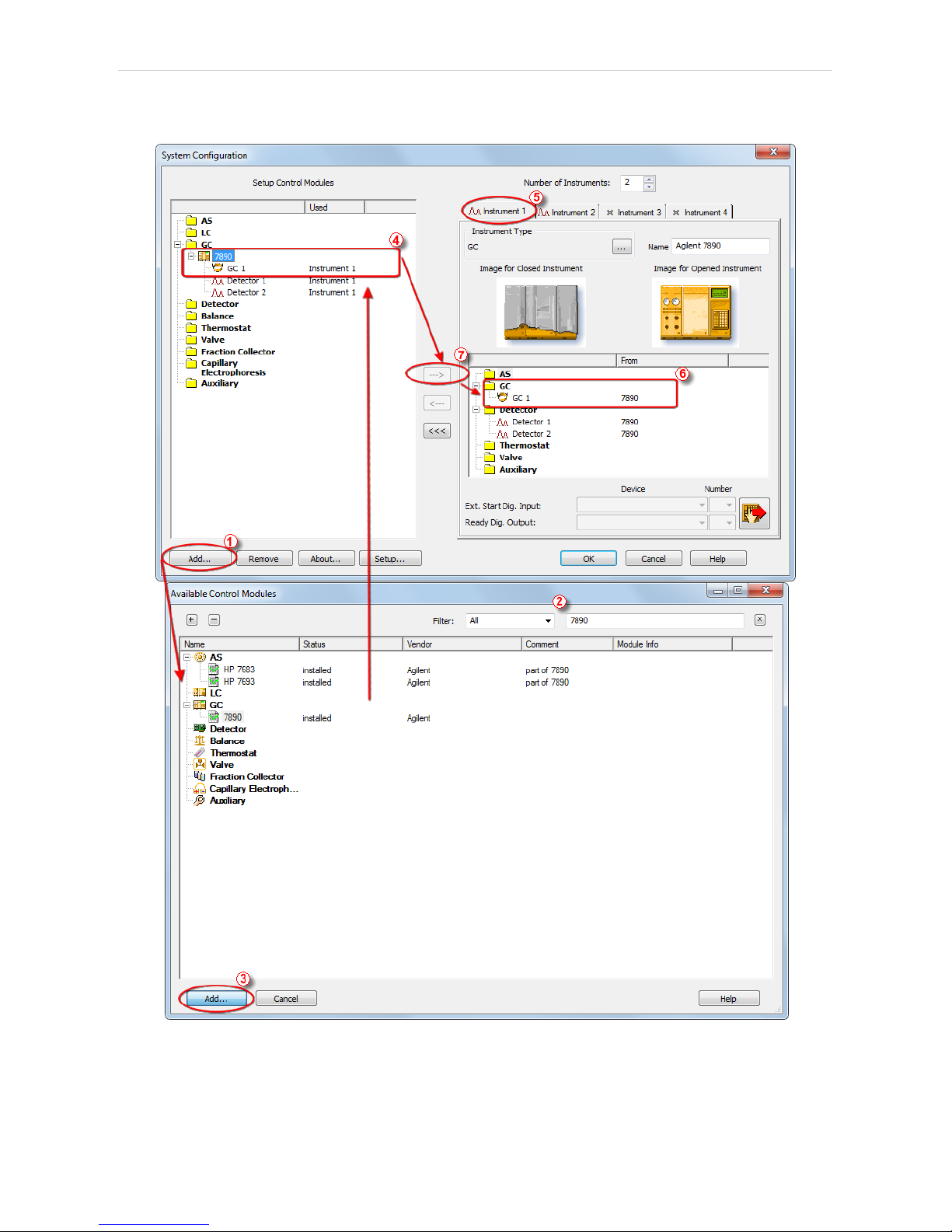
3.2 Clarity Configuration
Fig 2: System Configuration
- 5 -
Page 10

Agilent 7890 3 Installation Procedure
l In the System Configuration dialog press the Add button ① to invoke the
Available Control Modules dialog.
l Type "7890" into the searching field on the top of the dialog ② for quick
filtering out the desired instrument.
l Select the Agilent 7890 in the GC section and press the Add button.③
l The Agilent 7890 Setup dialog will appear.
Fig 3: Agilent 7890 Setup
l Fill in the IP address of the 7890 and IP address for receiving data (i.e. IP
address of computer with installed Clarity datastation). Ask your
company's IT person if you don't know them. A default IP address of most
Agilent GC's is 10.1.1.101 which is suitable only in case the GC is
connected directly to computer using separate network.
l Press the Autodetect button to read all settings from the instrument. Upon
successful detection the serial number of the GC will be displayed.
Note: In most cases it is recommended not to change the settings obtained
through the Autodetect function. However some modules (e.g. PCM,
valves or Aux Pressure modules) are not autodetected correctly and in
certain systems it is necessary to set them manually.
l Check the Keyboard Lock checkbox for ensuring the exclusive access to the
chromatograph. Apart from locking the keyboard of the device, this will also
prevent other users connected to the same network from connecting to the
chromatograph.
l Switch to the GC tab to verify the correct detection of injectors, inlets, detectors
and columns. Do not change the autodetected values.
l Switch to the Signals tab (for more details see the Agilent 7890 Setup
dialog section later in the manual ), select the correct number of signals
- 6 -
Page 11

3 Installation Procedure Clarity Controls
you want to acquire, name them and possibly check This Device Starts the
Run in Clarity / Clarity Starts This Device radiobutton. The Clarity Starts
This Device option should be checked only when the GC will not start the
acquisition (that means it will not be triggered by the GC Start button,
external start contact or autosampler). Press the OK button.
l On the Sampler tab verify the auto detected sampler version and
components, set the Syringe Size and Solvent Wash Mode.
l On Valves tab verify the identified valves, on the Aux tab verify the
detected auxiliaries.
l Press OK. The Agilent 7890 item ④ will appear in the Setup Control
Modules list of the System Configuration dialog.
l Drag the GC icon from the Setup Control Modules list on the left side to
the desired Instrument tab ⑤ on the right side ⑥ , or use the button ⑦
to do so.
Note: In case there is no detector used with 7890 it is necessary to add other
detector to the same Instrument (e.g. DEMO detector available on each
station), otherwise it would be not possible to send the method and start
the GC by Clarity.
- 7 -
Page 12
Agilent 7890 4 Using the control module
4 Using the control module
New GC tab appears in the Method Setup dialog, enabling the setting of
the GC control method. With an automatic sampler configured, AS tab also
appears, allowing the setting of the autosampler method.
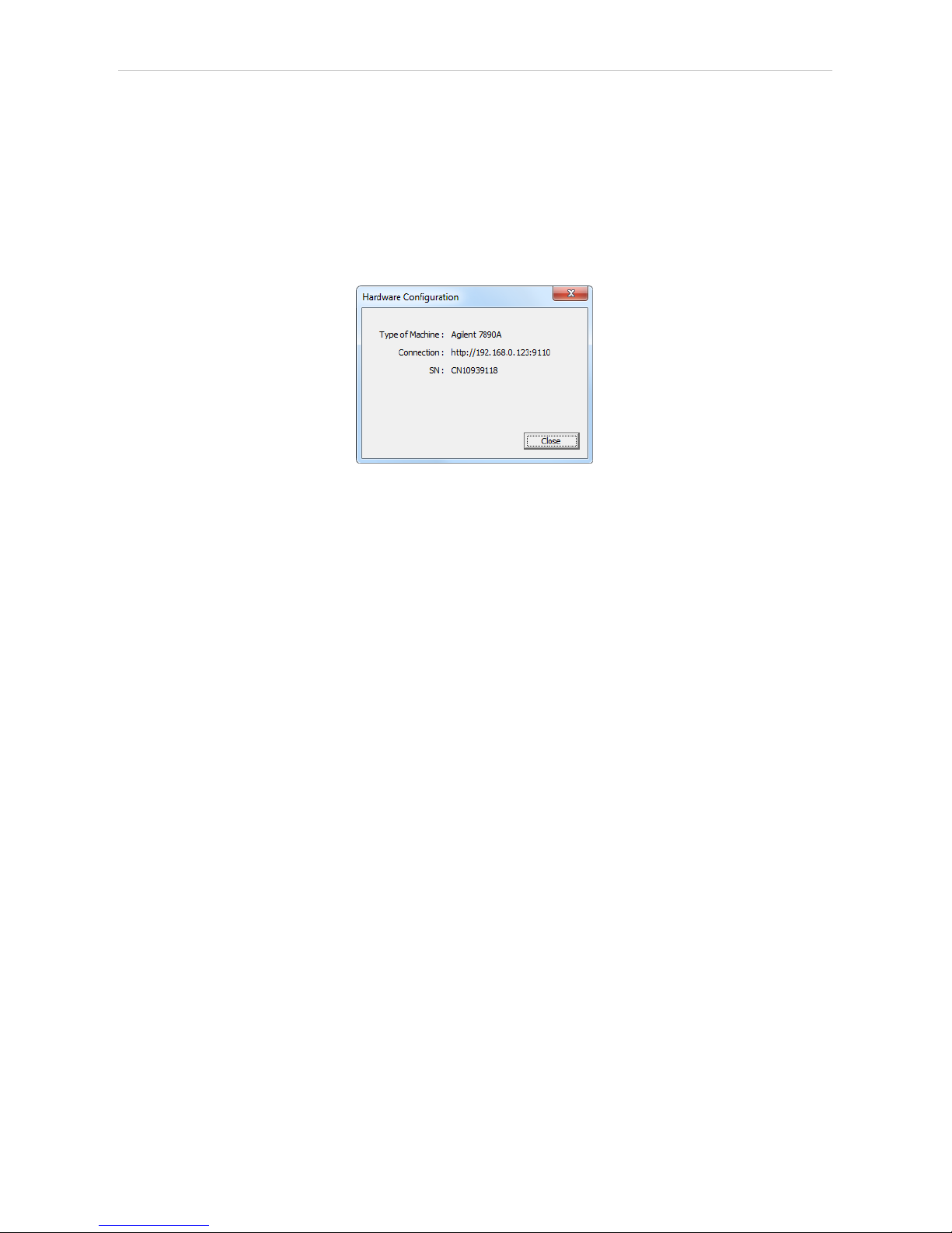
4.1 Hardware Configuration
Fig 4: Hardware Configuration
This dialog is invoked by pressing the GC Status button in the Method
Setup - GC dialog. Hardware Configuration dialog displays the type of the
chromatograph, it's serial number and the IP address and port to which it
is connected.
- 8 -
Page 13

4 Using the control module Clarity Controls
4.2 Method Setup - Autosampler
Fig 5: Method Setup - AS - Mode
Use Injector
Selects the injector which will be used.
Use Tray
Checks if Tray will have to be used.
Vial No. Shift
Sets the shift between numbers of vials injected by both injectors. Active
with both injectors and tray used.
- 9 -
Page 14

Agilent 7890 4 Using the control module
Fig 6: Method Setup - AS - Injector
Number of Injections
Sets the number of injections performed with every sample.
Multiple Injection Delay
Sets the delay between individual injections in case of multiple injections.
Pre Injection Dwell Time
Sets the time the needle remains in the inlet before the injection.
Post Injection Dwell Time
Sets the time the needle remains in the inlet after the injection.
Pre Washes
Sets how many times the syringe will be washed by a particular solvent or
sample before the injection.
Post Washes
Sets how many times the syringe will be washed by a particular solvent
after the injection.
Volume
Sets the percentage of the syringe volume washed.
Sample Pumps
Sets how many times the syringe plunger is moved up and down with the
needle in the sample.
Draw Speed
Sets the speed of drawing the sample.
Dispense Speed
Sets the speed of injecting the sample.
- 10 -
Page 15

4 Using the control module Clarity Controls
Viscosity Delay
Sets how many seconds the plunger pauses at the top of the pump and
injection strokes.
Depth offset
Sets the depth offset of the syringe needle.
4.3 Method Setup - GC
4.3.1 Oven/Zones
Fig 7: Method Setup - GC - Oven/Zones
This tab allows to set the parameters for oven and temperature zones.
Particular fields may vary, according to the configuration.
Oven : Max
Sets the maximal allowed temperature for the column oven.
Note: Please note that the maximum value may differ for certain GC models.
Equilibration
Sets the time of oven temperature equilibration.
Gradient Table
Sets the Heat Rate, desired temperature (Final Temp ) and time to hold
this temperature (Hold Time). The Total Time column will be calculated
automatically. In other words, for isothermal part of the temperature
gradient, the temperature set in Final Temp will be kept for the interval set
- 11 -
Page 16

Agilent 7890 4 Using the control module
in Hold Time. To delete a row, simply delete the value in the Heat Rate
column on that row.
Temperature Zones
Sets the temperature of particular zones.
Cryo Temp
Sets the temperature setpoint for the cryogenic cooling.
Quick Cool
Turns on/off the Quick Cool feature.
Fault
When checked, GC shuts the oven down if it does not reach setpoint
temperature after 16 minutes of continuous Cryo operation.
Timeout
Turns on/off and setting the setpoint for Cryo Timeout.
Post Run (Time and Temp)
Sets the time and temperature of the Post Run period.
- 12 -
Page 17

4 Using the control module Clarity Controls
4.3.2 Front (Back) Inlet
Fig 8: Method Setup - GC - Inlet
This tab governs the settings concerning the inlets of the Agilent 7890
chromatograph. According to configuration of particular chromatograph,
there can be Front Inlet or Back Inlet tabs, both with the same appearance.
Particular fields may vary, according to the type of the inlet set.
Temperature Mode
Defines the temperature mode for the inlet. Available for COC and PTV
inlets.
Carrier Gas
Sets the type of carrier gas used on this GC.
Temperature Gradient Table
Allows to edit temperature ramp for the inlet (up to three rates and
plateaus). Available for COC and PTV inlets.
Injection Pulse (Press + Time)
Sets the pressure and duration of pressure pulse during injection of the
sample. Available for PTV and Split/Splitless inlets.
Pneumatic Mode
Defines the operation mode for the injector port. Available for PTV and
Split/Splitless inlets.
Total Flow
Turns on/off and sets the flow rate for carrier gas. The value entered here
is used only when there are no columns defined on the GC, however the
- 13 -
Page 18

Agilent 7890 4 Using the control module
checkbox have to be checked in order to the inlet work properly. Available
for PTV, Purged Packed and Split/Splitless inlets.
Split Ratio
The ratio of split vent flow to column flow. This line appears only if the
columns in the flow path are defined. Available for PTV and Split/Splitless
inlets.
Purge Flow
Sets the flow rate from the purge vent. Available for PTV and Split/Splitless
inlets.
Purge Time
Sets the time, after the beginning of the run, when you want the purge
valve to open. Available for PTV and Split/Splitless inlets.
Saver (Flow +Time)
Turns on/off and setting the flow and time for the Gas Saver. Available for
PTV and Split/Splitless inlets.
Cryo Temp
Sets the temperature setpoint for the cryogenic cooling.
Quick Cool
Turns on/off the Quick Cool feature.
Fault
When checked, GC shuts the oven down if it does not reach the setpoint
temperature after 16 minutes of continuous Cryo operation.
Timeout
Turns on/off and setting the setpoint for Cryo Timeout.
Vent Flow
Sets the flow rate for venting. Available for PTV inlet.
Vent Press
Sets the pressure of gas used for venting. Available for PTV inlet.
Vent Time
Sets the time of venting. Available for PTV inlet.
Septum Purge
Turns on/off the Septum Purge function.
Septum Purge Flow
Sets the flow rate for Septum Purge.
Septum Purge Switching
Turns on/off the Septum Purge Switching function. Available for splitless
pneumatic mode.
Switch Time [min]
Sets the time of Septum Purge Switching function.
- 14 -
Page 19

4 Using the control module Clarity Controls
4.3.3 Column #
Fig 9: Method Setup - GC - Column
This tab allows to set the parameters for a column configured in the
Agilent 7890 Setup dialog. Particular fields may vary, according to the
column mode selected.
Length
Sets the length of the column.
Ins.Diameter
Sets the internal diameter of the column.
Film
Sets the thickness of coating of the column.
Inlet
Sets to which inlet is the particular column connected.
Detector
Sets to which detector is the particular column connected.
Mode
Sets the temperature mode of the column.
Pressure/Flow Gradient Table
Allows to edit the pressure or flow ramp for the column (up to three rates
and plateaus). Active in Pressure Ramp or Flow Ramp mode only.
Pressure
Sets the pressure of a carrier gas in the column. Active in Constant
Pressure mode only.
- 15 -
Page 20

Agilent 7890 4 Using the control module
Flow
Sets the flow rate of a carrier gas in the column. Active in Constant Flow
mode only.
Post Run (Flow or Pressure)
Sets the flow or pressure rate of a carrier gas after finishing the gradient.
Active in Pressure Ramp or Flow Ramp mode only.
- 16 -
Page 21

4 Using the control module Clarity Controls
4.3.4 Front (Back) Detector
Fig 10: Method Setup - GC - Detector
This tab allows to set the parameters for the detector configured in the
Agilent 7890 Setup dialog. Particular fields may vary, according to the
type of the detector set.
Makeup Flow
Turns the makeup gas flow on and off, eventually sets the flow. Available
for most detectors.
Makeup Gas
Sets the type of makeup gas used for detector. Available for most
detectors.
Constant Makeup Flow
Sets the constant makeup flow into the detector. In this mode, GC will
keep the actual makeup flow regardless of changes in the total flow during
the GC run. Available for most detectors.
Constant Column + Makeup Flow
Sets the constant combined flow into the detector. In this mode, GC will be
adjusting the actual makeup flow in order to keep the total flow constant.
Available for most detectors.
Flame
Turns the detector flame on and off. After turning on turns on the air and
hydrogen and initiates the ignition sequence.The temperature of the
detector must be greater than 150 °C for the flame to light. Available for
FID and FPD detectors.
- 17 -
Page 22

Agilent 7890 4 Using the control module
H2 Flow
Sets the hydrogen flow into the detector. The flow of hydrogen will be
turned off automatically after turning off the flame. Available for FID, FPD
and NPD detectors.
Air Flow
Sets the air flow into the detector. The flow of air will be turned off
automatically after turning off the flame. Available for FID, FPD and NPD
detectors.
Negative Polarity
Reverses the polarity of detector signal. Available for TCD detector.
Reference Flow
Sets the flow of reference gas for the detector. Available for TCD detector.
Dual
Turns on/off the Dual mode. Available for FPD detector.
Electronics
Turns on/off the detector electronics. Available for ECD detector.
Auto Adjust
Turns on/off the automatic bead voltage adjusting. When checked, Offset
field becomes active, allowing to set the desired current offset value.
When unchecked, Bead Voltage field becomes active, allowing to set the
voltage manually. Available for NPD detector.
Lit Offset
Sets the lit offset value. Available for FID, NPD and FPD detectors.
Bead Voltage
Sets the bead voltage. Field is active only with Auto Adjust checkbox
unchecked. Available for NPD detector. It is important to set the proper
voltage for actually installed bead because setting the voltage too high
can destroy the bead irreversibly.
Dry Bead during Warm-up
Turns on/off the Dry Bead function. This causes the detector to wait 5
minutes at 150°C during warming up. Available for NPD detector.
Bead Type
Sets the type of bead installed. It is important to set the proper type of
bead because improper setting can destroy the bead irreversibly.
Available for NPD detector.
- 18 -
Page 23

4 Using the control module Clarity Controls
4.3.5 Time Table
Fig 11: Method Setup - GC - Time Table
This tab allows to set the events that will be triggered during the run based
on the analysis time. This includes events like switching the detector
polarity, range or signal source (where applicable), setting temperatures
to detector / injector / auxiliary zones, controlling the valves etc. To delete
a row, simply delete the value in the Time column on that row.
- 19 -
Page 24

Agilent 7890 4 Using the control module
4.3.6 PCM
Fig 12: Method Setup - GC - Inlet
This tab governs the settings concerning the Pressure Control Modules
installed in the Agilent 7890 chromatograph. According to configuration of
particular chromatograph, there can be several tabs, both with the similar
appearance.
Pneumatics
Turns on/off the pneumatic control of a particular channel.
Mode
Sets the working mode of PCM Channel A.
Pressure
Sets the initial pressure (available only in Pressure mode).
Total Flow
Sets the initial Flow (available only in Flow mode).
Postrun Pressure
Sets the postrun pressure (available only in Pressure mode).
Postrun Flow
Sets the postrun Flow (available only in Flow mode).
- 20 -
Page 25

4 Using the control module Clarity Controls
Gradient Table
Sets the Pressure/Flow/Temperature rate, desired value and time to hold
this value (Hold Time). To delete a row, simply delete the value in the
Rate column on that row.
Heater
Turns on/off the heater.
Postrun Temperature
Sets the postrun temperature.
- 21 -
Page 26

Agilent 7890 4 Using the control module
4.3.7 Gradients
Fig 13: Method Setup - GC - Gradients
This tab displays the temperature gradient as set on the Method Setup -
GC - Oven/Zones tab.
- 22 -
Page 27

4 Using the control module Clarity Controls
4.4 Method Setup - Acquisition
Fig 14: Method Setup - Acquisition
Each detector allows to set the source of signal on the appropriate tab. To
switch to another detector, use the Select Detector field in the upper left
corner of the Method Setup - Acquisition dialog.
Signal Source
Selects the source of the signal (signal from a particular detector or
various internal and auxiliary signals, used for monitoring the state of the
device).
Signal Type
Selects the type of signal from the particular Signal Source.
Note: In case your GC has some non- standard detector installed (so called
Channel Partner detectors), it would be not possible to configure it in
Agilent 7890 Setup window, however its signal would be available for
acquisition. In such a case you have to select the signal according to
position of the detector.
Specific Signal
Selects the specific signal available for selected Signal Type.
Channel #
Selects the channel of the signal. Available for some signals only.
Sample Rate
Sets the frequency of the data sent from the Agilent 7890 detector to
Clarity , it has nothing to do with the frequency of the actual data
- 23 -
Page 28

Agilent 7890 4 Using the control module
acquisition in the instrument. The sample rate is common to all signals of
the same instrument.
Note: Onlyfor detector signal it is possible to change the sample rate, all auxiliary
signals are collected at 50 Hz sample rate. In case some of the collected
signals are auxiliary (e.g. oven temperature or column gas flow), all
signals will be sampled at 50 Hz.
Signal Range
Sets the range for the output signal. As the range is increasing, sensitivity
is decreasing, so the overall resolution is still the same (24 bit).
- 24 -
Page 29

4 Using the control module Clarity Controls
4.5 Method Setup - Valves
Fig 15: Method Setup - Valves
Each valve allows to set its parameters on the appropriate tab. To switch
to another valve, use the Select Valve field in the upper left corner of the
Method Setup - Valves dialog. Each type of valve has different parameters
available, thus the appearance of Valves panel depends on the type of
selected valve.
Initially On
Selects the initial state of the valve. Available for Switch and Other valves
only.
BCD Inverted
Available for Multiposition valves only.
Step Time [s]
Sets the Step Time. Available for Multiposition valves only.
Position
Sets the position. Available for Multiposition valves only.
Loop Volume [cm3]
Sets the Loop Volume. Available for Gas Sampling valves only.
Load Time [min]
Sets the Load Time. Available for Gas Sampling valves only.
Inject Time [min]
Sets the Inject Time. Available for Gas Sampling valves only.
- 25 -
Page 30

Agilent 7890 4 Using the control module
4.6 Using Dual Injector
In case your GC is equipped with two injectors, it is possible to use them
simultaneously. For this purpose it is necessary to have two unused
Instrument available.
l At first, ensure the GC has two injectors and tray correctly detected. See
also 7890 Setup - Sampler.
l Configure the GC, Sampler and Detector 1 on the first Instrument. See
also Clarity Configuration.
l Configure the Detector 2 on the second Instrument.
l First instrument serves as a master, all GC and AS method parameters will
be set here. In the method setup, AS tab, select the option Use Both
Injector and fill in the Vial No. Shift.
l On the second instrument, the AS and GC tabs are not available in
method setup. Only the Acquisition tab is available to set the configured
detector Range and Sample rate.
The sequence on first Instrument defines the vial numbers for first injector
and injection volume for both. The injection vial and injection volume in
the second instrument sequence are just informative, injection volume is
equal to that on first instrument, the vial number is equal to the vial
number in first instrument and the specified vial shift. To run the system,
prepare methods and sequences for both instruments, start the sequence
on second instrument and then the sequence on first instrument.
Sequence on the master Instrument (controlling the GC) needs to have
Active Sequence checkbox checked, the sequence on the second
Instrument needs to have it unchecked (passive sequence). Checkbox is
available on the Sequence Options dialog.
- 26 -
Page 31
4 Using the control module Clarity Controls
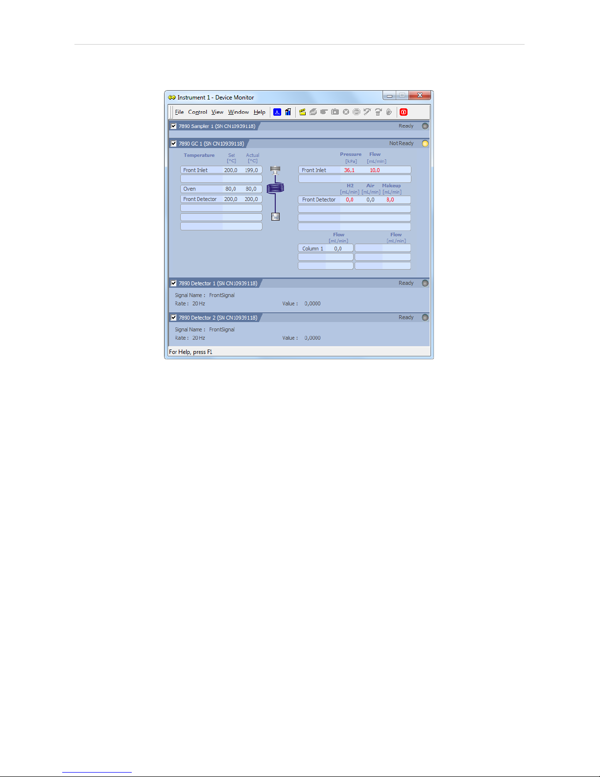
4.7 Device Monitor
Fig 16: Agilent 7890 Device Monitor
The Monitor window for the Agilent 7890 chromatograph displays all set
and actual temperatures in each temperature zone and the column oven.
It also displays gas flows and pressures for all important parts of the GC.
An unequilibrated values are displayed in red letters. Besides that, there
are sections for each detector and autosampler present. Detector section
shows names of the signals, its sampling rates and the actual value of a
particular signal.
- 27 -
Page 32

Agilent 7890 4 Using the control module
4.8 Agilent 7890 Setup
Agilent 7890 Setup dialog (accessible through the System Configuration
dialog) allows to view and manually set the hardware configuration of the
chromatograph. Most fields (with the exception of IP addresses ) can be
read from the chromatograph by using the Autodetect button, however it is
recommended to check the settings after autodetection. In case some part
of the GC cannot be autodetected, user has to set it manually.
4.8.1 Connection tab
Fig 17: Agilent 7890 Setup - Connection
IP address of 7890
Fill in the IP address of the Agilent 7890 chromatograph.
IP Address of This Computer
The IP address of the computer with installed Clarity datastation. In case
the computer is connected to more than one network, select the IP
address corresponding to the network with Agilent 7890 connected.
Autodetect
Read all settings from the instrument. Upon successful detection the serial
number of the GC will be displayed.
Please note that some modules (e.g. PCM, valves or Aux Pressure
modules) are not autodetected correctly and in certain systems it is
necessary to set them manually.
Keyboard Lock
Use this checkbox to ensure the exclusive access to the chromatograph.
Apart from locking the keyboard of the device, this will also prevent other
users connected to the same network from connecting to the
chromatograph.
- 28 -
Page 33

4 Using the control module Clarity Controls
4.8.2 GC tab
Fig 18: Agilent 7890 Setup - GC
After successful autodetection of GC parameters it is advisable to verify
them manually.
Front (Back) Inlet
Sets the type of inlet installed in the GC.
Front (Back, etc.) Detector
Sets the type of detector installed in the GC.
Column #
Check the presence of the columns installed in the GC.
Pressure Units
Sets the pressure units used for setting the pressure of a carrier gas. After
changing the units the values in the methods will be converted
automatically.
- 29 -
Page 34

Agilent 7890 4 Using the control module
4.8.3 Signals tab
Fig 19: Agilent 7890 Setup - Signals
This tab defines the number of signals that will be processed by Clarity.
Count
Defines the number of signals received by Clarity . These signals
correspond to Clarity detectors and will have their own sub-tabs in the
Method Setup - Acquisition dialog, if configured on the given Clarity
Instrument.
Signal 1 (..4)
Sets the name of the particular signal.
This Device Starts the Run in Clarity / Clarity Starts This Device
This radiobutton enables to start the analysis run from the Clarity. With
This Device Starts the Run in Clarity checked, the device is started prior to
Clarity by its front button or autosampler connected to this device and
passes the start to Clarity. When Clarity Starts This Device is checked,
Clarity is started prior to this device by separately wired autosampler,
Start button in Single Run or different device and then starts this device.
Note: The This Device Starts the Run in Clarity option is checked by default.
- 30 -
Page 35

4 Using the control module Clarity Controls
4.8.4 Sampler tab
Fig 20: Agilent 7890 Setup - Sampler
This tab displays the settings of the automatic liquid sampler
(autosampler) connected directly to GC. Settings on this tab may be read
from the chromatograph using the Autodetect button, however it is
advisable to verify them manually.
Use Sampler
Enables the autosampler for use with Agilent 7890 chromatograph.
Needs to be unchecked if you want to start the acquisition from the
Clarity.
Name
Allows to set the arbitrary name for the autosampler.
Type
Sets the type of the autosampler installed.
Front (Back) Injector
Enables the use of the particular injector.
Syringe Size
Sets the size of the syringe installed.
Solvent Wash Mode
Sets the solvent wash mode for the autosampler.
Tray
Sets the presence of an autosampler tray.
- 31 -
Page 36

Agilent 7890 4 Using the control module
4.8.5 Valves tab
Fig 21: Agilent 7890 Setup - Valves
This tab displays the settings of valves in the GC. Settings on this tab may
be read from the chromatograph using the Autodetect button, however it is
advisable to verify them manually.
4.8.6 Aux tab
Fig 22: Agilent 7890 Setup - Aux
This tab displays the settings of auxiliary devices in the GC. Settings on
this tab may be read from the chromatograph using the Autodetect button,
however it is advisable to verify them manually.
- 32 -
Page 37

4 Using the control module Clarity Controls
4.8.7 PCM tab
Fig 23: Agilent 7890 Setup - PCM
This tab displays the settings of Pneumatic Control Modules in the GC.
Settings on this tab may be read from the chromatograph using the
Autodetect button, however it is advisable to verify them manually.
- 33 -
Page 38

Agilent 7890 5 Report Setup
5 Report Setup
Fig 24: Agilent 7890 - report preview
All chromatograph- specific settings (e.g. temperatures set to particular
temperature zones) are reported as a part of the data displayed by the use
of Instrument Control checkbox of the Report Setup - Method dialog.
- 34 -
Page 39

Agilent 7890 6 Troubleshooting
6 Troubleshooting
When the remedy for some problem cannot be discovered easily, the
recording of communication between Clarity and the chromatograph can
significantly help the DataApex support to discover the cause of the
problem.
The recording can be enabled by adding or amending the COMMDRV.INI
file in the Clarity installation directory (C:\CLARITY\CFG by default). The
file can be edited in any text editor (e.g. Notepad). Following section
should be edited or added:
[TCP_IP 192.168.0.100:9110]
echo=on
textmode=on
filename=Agilent7890_%D.txt
reset=off
Note: Instead of 192.168.0.100:9110 type correct IP address and port used to
communicate with the Agilent 7890 chromatograph. This port number is
displayed when the GC Status button in the Method Setup - GC dialog is
invoked or in the Agilent 7890 Setup dialog.
Note: %D (or %d) in the filename parameter means that the log will be created
separately for each day. The reset=off parameter disables deleting the
content of the log each time the station is started during the same day.
The created *.TXT files will greatly help in diagnosis of unrecognised
errors and problems in communication.
- 35 -
 Loading...