

Page 1

Page 2

Data Aire, Inc. reserves the right to make design changes for the purpose
of product improvement or to withdraw any design without notice.
Page 3

Table of Contents
1.0 Introduction ............................................................................................................ 4
1.1 Standard Features .......................................................................................... 4
1.2 Operational Features ...................................................................................... 4
1.3 Diagnostics and Service Features .................................................................. 5
1.4 Conditions and Data Displayed ...................................................................... 5
1.5 Functions Displayed ....................................................................................... 5
1.6 Warnings and Alarm Displayed ....................................................................... 5
1.7 Historical Data Displayed ............................................................................... 6
1.8 Programmable Selections .............................................................................. 6
2.0 Getting Started ......................................................................................................7
2.1 Powering the Unit ON/OFF ............................................................................. 8
2.2 Accessing Menus/Passwords .........................................................................8
2.2.1 Changing the Service Level Password ................................................... 9
3.0 Menu Settings ...................................................................................................... 10
3.1 Menu A - ON/OFF ......................................................................................... 10
3.2 Menu B - Setpoints ....................................................................................... 10
3.3 Menu C - Clock/Scheduler ............................................................................ 11
3.4 Menu D - Input/Output .................................................................................. 15
3.5 Menu E - Historical Data ............................................................................... 17
3.6 Menu F - Information..................................................................................... 19
3.7 Menu G - Network Cong ............................................................................. 20
3.8 Menu H - Calibrate Sensors.......................................................................... 21
3.9 Menu I - Manual Control ............................................................................... 23
3.10 Menu J - Factory Settings ............................................................................ 24
3.11 Menu K - Alarms and Limits .........................................................................28
3.12 Menu L - Congure I/O ................................................................................35
4.0 Alarms/Clearing Alarms ...................................................................................... 40
4.1 Acknowledging an Alarm ............................................................................... 40
4.2 Clearing Alarms.............................................................................................42
5.0 Mini dap4 Control Logic ......................................................................................43
Temperature Sensor Chart ......................................................................................... 51
Addendum for the gPod Model ..................................................................................55
3 • Mini dap4 User Manual
Page 4

1.0 INTRODUCTION
The Mini dap4 continues the tradition of advanced electronic devices from Data Aire for monitoring and control of
computer room air conditioning units which began in 1977. Each generation has provided more accurate monitoring
information and exibility in controlling the unit.
The Mini dap4 offers the denite answer for precision environmental control. The Mini dap4 control system not only
controls and monitors temperature, humidity, airow and cleanliness, but also provides component run times, alarm
history and an automatic self-test of the microprocessor. All messages are sequentially displayed on a backlit LCD
(liquid crystal display). The Mini dap4 can interface with a variety of building management systems (BMS).
1.1 STANDARD FEATURES
Stand Alone Panel: Service terminals or additional devices are not required for programming or monitoring functions
Microprocessor Based: 32 bit, 44 MHz Micro controller. State-of-the-Art technology and reliability in a program-
mable logic control module
LED Illuminated Keys: Six highly reliable keys allow movement through the menus
Backlit Liquid Crystal Display (LCD): Information is displayed and presented in a format that is easily viewed and
understood
All Settings are Programmable from the Face of the Panel: Expedient and user friendly
Layered and Forward and Backward Menu Access: Facilitates programming with exible operation
USB Port: Allows download/upload of software
Multi-Level Password Access: Controls any unauthorized changes to settings and system functions
Database of Unit and Room Conditions: Historical data that facilitates service, apparatus set-up and ne tuning of
setpoints
Factory Programmed Menus: Menus that pertain to the type and method of cooling, reheat and humidication
based on the unit’s components and options
Programmed Settings and Historical Data are Saved in Flash Memory: Non-volatile memory stored so all control
settings and operational parameters are secured indenitely even during a power outage
Calibrated Temperature and Humidity Sensors: Accurate and consistent regulation especially in multiple unit applications
1.2 OPERATIONAL FEATURES (Optional features may require additional components and/or sensors)
Sequential Load Activation: Time and temperature based logic that sequentially starts and stops stages of cooling
and reheat
Compressor Short-Cycle Control: Prevents excessive compressor wear by using restart and anti-cycle limits
Automatic or Manual Restart: Restart methods are programmable in the event of a power failure
Humidity Anticipation: Modies the humidity setpoint to reduce excess humidication and dehumidication
Dehumidication Mode Lockout: Inhibits dehumidication if not required for system performance
Start Time Delay:
Automatic Compressor Rotation: Periodically rotates the lead/lag compressor sequence to balance run times
4 • Mini dap4 User Manual
Programmable time delay staggers the start-up of multiple units to prevent high power demand peaks
Page 5

1.3 DIAGNOSTICS AND SERVICE FEATURES
Alarms Displayed in Order of Occurrence: Sequence with time of occurrence assist in diagnosing the cause of
alarm(s)
Programmable Delays for Optional Alarms: Reduces nuisance and false alarms caused by temporary or transient
conditions
Manual Diagnostics Program: Provides accessible procedures to test the processor and major system components
Adjustable Alarm Limits: Threshold levels for temperature and humidity alarms are programmable
Optional Programmable Alarm Contact: Allows selection of an alarm matrix that will operate the contact
Audio Alarm Tone: Three (3) programmable alarm tones are available
Alarm History: 100 alarms are stored for system follow-up
1.4 CONDITIONS and DATA DISPLAYED
UNIT TYPE: Data Aire model type TEMPERATURE SETPOINT: Current temperature setpoint (°F or °C)
TIME: Current time (hour/minute) UNIT ID/ZONE ID: Assigned unit ID and Zone Number*
UNIT STATUS: ON or OFF TEMPERATURE: Current return air temperature (°F or °C)
HUMIDITY: Current return air humidity (%) HUMIDITY SETPOINT: Current humidity setpoint (%)
DATE: Current date (month/day/year) DISCHARGE AIR: Current chilled water temperature (°F or °C)*
CHILLED WATER TEMPERATURE: Current Temperature (°F or °C)*
1.5 FUNCTIONS DISPLAYED
COOLING: 1st stage, 2nd stage* HUMIDIFICATION: Appears when operating*
DEHUMIDIFICATION: Appears when operating REHEAT: Appears when operating
CHILLED WATER FLOW: Valve Opening: 0 - 100%
1.6 WARNINGS and ALARMS DISPLAYED
HIGH TEMPERATURE WARNING LOW TEMPERATURE WARNING
HIGH HUMIDITY WARNING LOW HUMIDITY WARNING
POWER FAILURE RESTART NO AIRFLOW
DIRTY FILTER* FIRESTAT TRIPPED
MANUAL OVERRIDE* HUMIDIFIER PROBLEM*
MAINTENANCE REQUIRED TEMPERATURE SENSOR FAILURE
HUMIDITY SENSOR FAILURE SMOKE DETECTOR*
CUSTOM MESSAGE* FAN MOTOR OVERLOAD*
DISCHARGE AIR SENSOR ERROR* HIGH CONDENSATE WATER LEVEL
STANDBY PUMP ON* PERSON TO CONTACT ON ALARM
HIGH PRESSURE/COMP FAILS COMP 1 NO WATER FLOW*
HIGH PRESSURE/COMP FAILS COMP 2*
For Chilled Water units, 3 optional alarms can be selected
For DX units, single circuit, 2 optional alarms can be selected
For DX units, dual circuits, 1 optional alarm can be selected
* This optional feature or data display may require additional components and/or sensors
5 • Mini dap4 User Manual
Page 6

1.7 HISTORICAL DATA DISPLAYED
EQUIPMENT RUNTIMES: Blower, compressor 1, compressor 2 (as applicable), reheat, dehumidication, Energy
Saver*, humidier, condenser and chilled water
ALARM HISTORY: Alarm list with time and date of occurrence
LAST 24 HOURS: High and low temperature, high and low humidity
AVERAGE PERCENT OF CAPACITY LAST HOUR: Compressor(s), humidier, reheat strips and water valve
1.8 PROGRAMMABLE SELECTIONS
TEMPERATURE SETPOINT TEMPERATURE DEADBAND
HIGH TEMPERATURE ALARM LIMIT LOW TEMPERATURE ALARM LIMIT
HUMIDITY SETPOINT HUMIDITY DEADBAND
HIGH HUMIDITY ALARM LIMIT LOW HUMIDITY ALARM LIMIT
COMPRESSOR LEAD/LAG SEQUENCE RESET EQUIPMENT RUNTIMES
AUDIO ALARM MODE HUMIDITY ANTICIPATION
COMPRESSOR SHORT CYCLE ALARM DEHUMIDIFICATION MODE
LOW DISCHARGE TEMPERATURE ALARM LIMIT* POWER RESTART/RESTART MODE
SYSTEM START DELAY MANUAL DIAGNOSTICS
MESSAGE FOR OPTIONAL ALARM 1, 2, 3 PERSON TO CONTACT ON ALARM
DELAY FOR OPTIONAL ALARM 1, 2, 3 TEMPERATURE SCALE
COMPRESSOR ASSIST TO ENERGY SAVER REHEAT STAGES
REMOTE ALARM SELECTION COMPRESSORS
FIRESTAT TEMPERATURE ALARM LIMIT HUMIDIFIER
CALIBRATE TEMPERATURE SENSOR WATER VALVE VOLTAGE RANGE
CALIBRATE HUMIDITY SENSOR REVERSE ACTING WATER VALVE
SCHEDULED NORMAL MAINTENANCE COOLING STAGE to STAGE BAND
NETWORK PROTOCOL* ANALOG OUTPUT for MOD CW
CALIBRATE DISCHARGE AIR SENSOR* ANALOG OUTPUT for MOD HUMID
CALIBRATE CHILLED WATER TEMPERATURE SENSOR* WATER VALVE MODE
6 • Mini dap4 User Manual
Page 7
2.0 GETTING STARTED
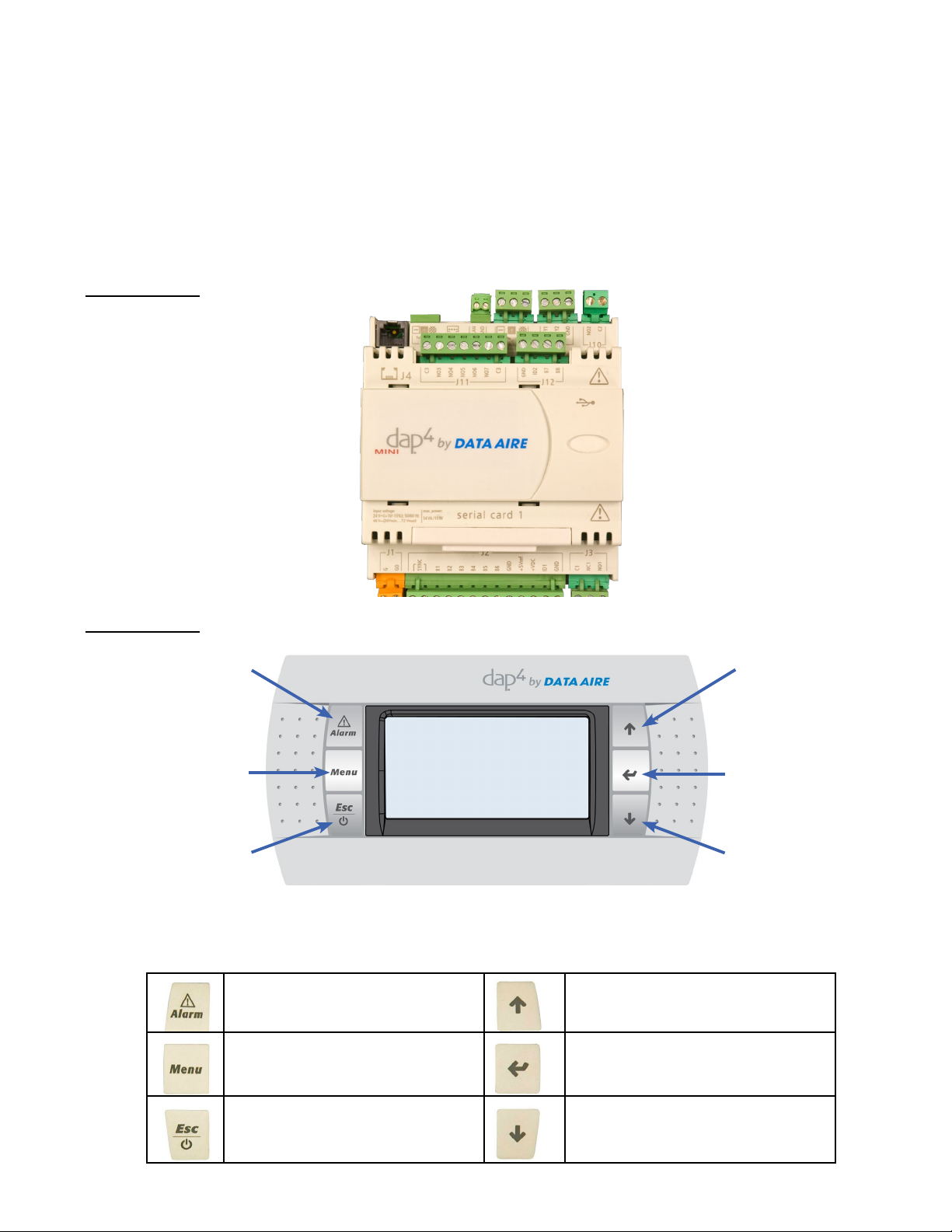
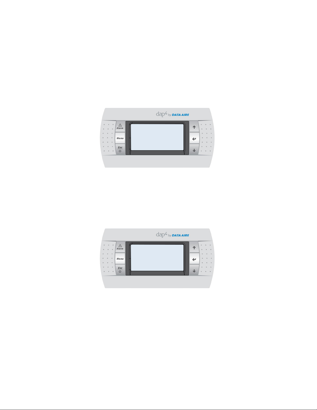
The Mini dap4 consists of two main components: the control module and the display panel. The control module is
located in the electrical panel. The display panel is remotely mounted. The two are connected by special telephone
type cable harness (units may be ordered with longer cables for optional remote wall mounting).
Note: Factory cable is required. This is a custom made cable and must be ordered from Data Aire. A regular telephone cable will not operate.
All data displayed on the display screen originates from the control module. The display panel has a backlit LCD (liquid crystal display). There are six keys on the face of the display panel to retrieve or enter settings.
Control Module
Display Module
Display Alarm
Enter Menu
Return to
previous
screen or
hold to turn
On or OFF
Button Functions
Allows viewing of active alarms
Silences audible alarms
Resets active alarms
Allows entry to Main Menu
Up
Enter/Select
Down
Allows scrolling to next screen
Allows values changes (increase)
Allows entry to Menus
Advances cursor
Return to previous screen
Hold ve seconds to turn ON or
OFF
7 • Mini dap4 User Manual
Returns to previous screen
Allows value changes (decrease)
Page 8

The main loop will ip though a series of screens that allow you to see set-points, current unit status (temperature,
relative humidity and operating mode – cooling, humidication, etc.).
MINI-PLUS
08/02/11 08:25
Unit Status: UnitOn
Temp SP 72.00 Hum SP 50%
2.1 POWERING the Unit ON/OFF
Before powering unit ON, check that power is available and proper connections have been completed.
Turn the disconnect switch to the ON position. The controller display keys and screen will illuminate and the processor will conduct a self-test (the screen will remain illuminated with no messages until the testing is complete). The
self-test takes approximately 20 seconds. Once completed, the Main Menu screen will be displayed. For initial programming of setpoints, alarms, delays, etc., it is not necessary to have the unit ON. With the unit in the “OFF by Key”
mode, all settings are available to view and change (other than Menus J – Factory Settings and L – Congure Inputs/
Outputs) if the proper password is entered.
The Main Menu screen will display the unit type, date and time, and unit status. In addition, the screen will scroll and
display the temperature, relative humidity and operating mode.
The Unit Status will indicate the unit: ”OFF by Key”
The unit may be turned ON at any time. Hold the ESC key for approximately 5 seconds. The display will continue to
scroll and display messages. At the same time the unit status is changed to “Unit On”. Once powered there will be a
5-600 second start delay indicated by “Time Before Start: XXs”.
Note: The start time delay is programmable from 5-600 seconds (Menu J – Factory Settings). The factory setting is 5
seconds.
2.2 ACCESSING MENUS/PASSWORDS
To access any Menu a numerical password is required. There are two levels of password:
• SERVICE LEVEL • FACTORY LEVEL
The SERVICE LEVEL password allows viewing and changes to the following Menus:
A. On/Off D. Input/Output G. Network Conguration K. Alarms/Limits
B. Setpoint E. Historical Data H. Calibrate Sensors
C. Clock/Scheduler F. Information I. Manual Control
The FACTORY LEVEL password allows changes to the SERVICE LEVEL Menus plus the following Menus:
J. Factory Settings L. Congure Inputs/Outputs
The ZONE MASTER is an optional feature and requires a factory provided activation code. Contact factory if ZONE
MASTER control is required.
8 • Mini dap4 User Manual
Page 9
To enter the Menu and Sub-Menu screens, press the MENU key on the display panel. A password will be requested.
The password is a four digit entry (including 0). Units are shipped from the factory with the password requirement
bypassed to accommodate start-up and set-up.
The display screen will have the following message:
The Service Level Password setting from the factory is: 0000
Security Access
Insert Service/Factory
level password: 0000
The cursor will be ashing at the top of the screen. Press the ENTER key to move the cursor to the rst eld. Press
the UP or DOWN keys to increase or decrease the value. Once the value is entered, press the ENTER key to move
to the next input. Increase or decrease t
he value by pressing the UP or DOWN keys. Once the desired value is shown,
press the ENTER key to move to the next eld.
Once the correct password is entered and accepted, the Menus will display on the screen. Only those Menus allowed
through the Service Password will be available. Use the UP or DOWN keys to scroll through the available Menus.
Note: Factory Level Menus are for conguring the unit. The Mini dap4 controller is used for a variety of equipment
types. The controller is based on the unit type, unit components and options. Under normal circumstances these
menus should not be changed. If they need to be changed, please consult with Data Aire engineering or service personnel before proceeding.
2.2.1 Changing the Service Level Password
The Service Level password can be changed while the service level menu is active.
▼ After entering the Service password press Menu key again then press Down key, the screen will display the following message:
Service Security
Change service level
password (PWI): 0000
▼ Press the ENTER key. The cursor will highlight the rst input. Change the input by pressing the UP or
DOWN
Once the selected number is displayed, press the ENTER key to move to the next input. Repeat the same steps for
each input.
After the last input has been entered the new password is stored. Press the MENU key to return to Main Menu.
9 • Mini dap4 User Manual
key.
Page 10
3.0 ENTERING MENU SETTINGS
3.1 MENU A – ON/OFF
Use the UP or DOWN key to scroll through the menus. Once the desired menu is highlighted, press the ENTER key.
MENU A allows Start-Up Delay Time, Start-Up Mode and ON/OFF to be changed from the factory settings (the Service Level password is required for entry).
The following will appear on the display screen:
On/Off Unit
Start-up Delay: 5s
Start-up Mode: On
Hold ESC for 5 seconds
to turn unit ON or OFF
The cursor will be ashing at the upper left hand corner. Press the ENTER key. The cursor will move to the “Start-up
Delay”. The start-up delay is the time before the blower starts after being powered ON and the processor has completed its self-test. Press either the UP or DOWN button to change the delay time. The range is 5 to 600 seconds.
Once a time is selected, press the ENTER key to save the setting and move to the next line “Start-Up Mode”.
Press the UP or DOWN keys to change the mode from ON to OFF or from OFF to ON. The setting will determine
what the unit will do if power is interrupted. With the setting ON, the unit will automatically start once the self-test is
completed. With the setting OFF, the unit will require manually starting by holding the ESC key for ve (5) seconds.
Depending on which selection is made (ON or OFF), the Status will display – Unit On or Unit Off by Key
Once selections are made, leave MENU A by pressing the MENU key. The Main Menu screen will continue to display
other menus (B, C, E and F). To look at any of these menus scroll to the desired menu. Press the ENTER key. If you
choose to return to the Main Screen, press the ESC key.
3.2 MENU B - SETPOINTS
MENU B allows viewing and changing of Setpoints (Service Level password is required for entry)
Press the UP or DOWN key until “B. Setpoint” appears and is highlighted. Press the ENTER key.
Use the UP or DOWN key to scroll through the screens. Menu B has two screens.
The following will appear on the rst Menu B screen (values are for reference only):
Setpoints
Temp Setpoint: 72.0oF
Temp Deadband: 2.0oF
Stage-To-STAGE: 0.3oF
10 • Mini dap4 User Manual
Page 11
Press the UP or DOWN key. The following will appear on the screen:
Setpoints
Humidity Setpoint: 50%
Humidity Deadband: 3%
Engy Svr SetPt: 50.0oF
Deadband: 1.0oF
Change Over: 2.0oF
FACTORY SETTINGS:
TEMPERATURE: 72.0°F (Temperature range: 65 - 85°F)
DEADBAND: 2.0°F (Temperature Deadband range: 1 - 5°F)
STAGE TO STAGE: 0.3°F (Stage-to-Stage range: 0.3 - 3.0°F)
HUM SETPOINT: 50% (Humidity range: 25-70%)
HUM DEADBAND: 3% (Humidity deadband range: 1 - 15%)
ENGY SVR SETPT: 50.0°F (Setpoint range: 40.0 - 60.0°F)
DEADBAND: 1.0°F (Deadband range: 1.0 - 5.0°F)
CHANGE OVER: 2.0°F (Change over range: 2.0 - 5.0°F)
If Humidity Anticipation is turned ON in humidity setting under Menu J - Factory Settings, the following page appears
for reference (non-edit able):
Humidity Anticipation Setpoints
Humidity Setpoint: 50%
Temperature Offset: 3%
Anticipation SP: 5.3%
To change the value of any one of the setpoint values, move the cursor by pressing the ENTER key to the desired setpoint. The cursor will ash on the input value. Press the UP or DOWN button to increase or decrease the value. Once
the desired setpoint value has been changed, press the ENTER key to move to the next setting or until the cursor is at
the top of the screen.
Exit the Setpoint Menu by pressing the ESC Key. The display screen will return to the MAIN MENU. Use the UP or
DOWN Keys to advance to another Menu or press the ESC Key to return to the normal operating mode.
Note: Changes to any Setpoint input will remain and can only be changed manually (as described above).
3.3 MENU C – CLOCK/SCHEDULER
MENU C allows programming for setting night set-back, week-end and special day schedules.
Menu C should only be used for non-critical applications where units may be cycled off without any damage
to sensitive electronic equipment. The typical application is comfort cooling where units may be shut down
during non-working hours.
11 • Mini dap4 User Manual
Page 12
Enter Menu C by pressing the ENTER key. The following message will be displayed (values are for reference only):
Clock Settings
Day: Saturday
Date: 05/16/11
Hour 09:39
To change the date or time, move the cursor by pressing the ENTER key to the date. To change the date, use the UP
or DOWN keys. By pressing the ENTER key the cursor will move from segment to segment. Only the UP and DOWN
keys will change the value. The day will automatically change when the date has been altered.
Press the ENTER key until the cursor is in the title block (upper left hand corner). Press the UP or DOWN key to see
the next screen.
The following will be displayed (values are for reference only):
Set-Back Setting
Set-Back Enable: No
Override Time: 12Hrs
Cooling Offset 5.0oF
Humidity Offset: 10%
Dehumidify Offset: 10%
Note: Leaving the “Set-Back Enable” as NO, the set-back feature is non-operational and is the recommended
setting for applications with constant load and cooling requirements.
The factory setting is NO
Ranges:
Override Time - the range is 1-12 hours
Cooling Offset - the range is 0-30°F
Heating Offset - the range is 0-30°F
Humidify Offset - the range is 0-30%
Dehumidify Offset - the range is 0-30%
If Set-Back enable is YES, the Override Schedule will appear as the following (values are for reference only):
Set-Back Setting
Set-Back Enable: Yes
Override Schedule No
Override Time: 12Hrs
Cooling Offset 5.0oF
Humidity Offset: 10%
Dehumidify Offset: 10%
To change values, move the cursor to the desired input by pressing the ENTER key. Change the value by pressing
either the UP or DOWN key. Once all changes are made to inputs on screen, move the cursor to the top and press
the UP or DOWN keys to move to the next screen or press the MENU key to return to Main Menu screen.
12 • Mini dap4 User Manual
Page 13

Week Day Scheduler (only appears if the above Set-Back Enable selection was YES)
From the “Set-Back Settings” screen (with cursor at the top), press the DOWN key.
The following will be displayed (values are for reference only):
Week Day Scheduler
Day: MONDAY
Copy to: Monday No
1: 06:00 Normal SP
2: 17:00 Normal SP
3: --:-- ---------
4. --:-- ______
Setting
Screen Inputs
Press the ENTER key to move the cursor. The cursor will ash at the day (Monday). By pressing the UP or DOWN
key all the days of the week can be viewed (or selected).
Press the ENTER key. The cursor will ash on the “Copy to: Day” Pressing the UP or DOWN key all the days of the
week can be viewed.
The “Copy to:” function allows the user to copy setting from other days without going through the settings routine. By
pressing the ENTER key, position the cursor on the Day: Press the UP or DOWN keys to scroll through the days
of the week. Select the day that has been programmed and is to be copied. Press the ENTER key. The cursor
will ash on the “Copy to:”. Scroll through the days using the UP or DOWN key. Select the day to copy. Press the
ENTER key. The cursor will ash by the NO message. Press the UP or DOWN key to change for to YES. Press the
ENTER key. The display will have a SUCCESSFUL COPY message (which quickly is automatically removed).
The cursor will return to the title block. Repeat the same step for each day to be copied or select ALL.
▼ Press the ENTER key. The cursor will ash on the “NO or YES” setting. Pressing the UP or DOWN key will
change from YES to NO or NO to YES. Leave in the NO setting until selections have been made.
▼ Press the ENTER key. The cursor will ash on the rst time setting. All time is on a 24 hour clock (i.e. 6:00 PM =
1800 hours). The start time (line # 1) is selected by pressing the UP or DOWN key.
▼ Press the ENTER key to change the hour. By pressing the UP or DOWN key, the hour will change. Once the correct hour is selected, press the Enter key.
The cursor will ash on the minutes. By pressing the UP or DOWN key, the minutes will change. Once the correct
minutes are selected, press the Enter key.
The cursor will be positioned on the settings input. Press the DOWN key to view the available selections:
Set-Back
Normal SP (setpoint)
Turn Off
▼ Press the ENTER key. The cursor will ash on the second time setting.
Repeat the steps to set the second time setting (and third and fourth if used).
Once the settings are complete, with the cursor in the title block, press the DOWN key to advance to the next screen
or press ESC to return to the Main Menu or press the ESC key to return to normal operation.
13 • Mini dap4 User Manual
Page 14
The following will be displayed (values are for reference only):
Holiday Scheduler
Date Date
Start Stop Settings
07/04 07/05 Turn Off
--/-- --/-- -----------
--/-- --/-- -----------
Available settings:
Normal SP
Turn Off
Set-Back
Once the settings are complete, with the cursor in the title block, press the DOWN key to advance to the next screen
or press ESC to return to the Main Menu or press the ESC key to return to normal operation.
The following will be displayed (values are for reference only):
Special Day Scheduler
Day Day Setting
SD:1 --/-- -------- SD:2 --/-- -------- SD:3 --/-- -------- SD:4 --/-- -------- SD:5 --/-- -------- SD:6 --/-- ---------
Available settings:
Normal SP
Turn Off
Set-Back
Once the settings are complete, with the cursor in the title block, press the DOWN key to advance to the next screen
or press ESC to return to the Main Menu or press the ESC key to return to normal operation.
14 • Mini dap4 User Manual
Page 15
3.4 MENU D – INPUT/OUTPUT
MENU D is a view only menu allowing the user to view the various input and outputs.
To view, press the Menu key. A prompt for the password will be displayed on the display module. Once the password
is entered, the Main Menu screen will display the various menus. Scroll through the menus using either the UP or
DOWN keys. Move Menu D to the highlighted area and press the ENTER key.
The following will be displayed (values are for reference only):
Digital Inputs
Digital Inputs
1 2 5 6 7 8
q = Input is Active
▼ Press the DOWN key to view the next screen.
The following will be displayed (values are for reference only):
Digital Outputs
q q q 4 5 6 q q
q = Output is Energized
▼ Press the DOWN key to view the next screen.
The following will be displayed (values are for reference only):
Analog Input
Humidity
Input B02: 44.2
▼ Press the DOWN key to view the next screen.
15 • Mini dap4 User Manual
Page 16
The following will be displayed (values are for reference only):
Analog Input
Retur n Air Temp
Input B07: 70.8F
▼ Press the DOWN key to view the next screen.
The following will be displayed (values are for reference only):
Analog Output 2
Chilled Water Valve
Output 8.50vdc
▼ Press the MENU key to return to the Main Menu. Choose another Menu by pressing the UP or DOWN keys or
press ESC to return the normal operating mode.
16 • Mini dap4 User Manual
Page 17
3.5 MENU E – HISTORICAL DATA
MENU E allows viewing alarms, component runtimes and resetting of component runtimes
The rst screen will display the most recent alarm (if any had occurred).
The following will be displayed (values are for reference only):
Time and Date of Alarm
Alarm Type
Humidity at time of occurrence
Chilled Water temperature at time of occurrence (if applicable)
Discharge Air Temperature at time of occurrence (if applicable)
18:29:26 9/10/11
-> Scroll Up/Down?
Humidity High
Humidity: 59%
Return Air: 74.2oF
Chilled Water: 0.0
o
F
To view consecutive alarms press the ENTER key moving the cursor into the -> eld.
▼ Press the UP key and the display will show the previous alarm, with time and date. Continue to press the UP key
to view all alarms. Once the last listed alarm is viewed, press the ENTER to move the cursor back to the top of the
screen.
The screen will display the following:
Run Hours 1 Reset
Blower: 0000 No
Comp 1: 0000 No
Comp 2: 0000 No
Reheat: 0000 No
Humidity: 0000 No
Dehum 0000 No
▼ Press the ENTER key to move the cursor. The cursor will ash the reset choice of NO or YES. To reset and clear
runtimes, press the UP or DOWN key.
▼ Press the ENTER key until the cursor is ashing on the title line. Press the DOWN key to move to next screen.
▼ Press the ENTER key to move the cursor. The cursor will ash the reset choice of NO or YES. To reset and clear
runtimes, press the UP or DOWN key.
▼ Press the ENTER key until the cursor is ashing on the title line. Press the DOWN key to move to next screen.
17 • Mini dap4 User Manual
Page 18

The screen will display the following:
Run Hours 2 Reset i
Engy Svr: 0000 No
CW Cool: 0000 No
Cond Aux: 0000 No
Reset all Runtimes: No (or Yes)
With the cursor ashing on the title line, press the UP or DOWN key to review the alarms or runtimes or press the
MENU key to return to the Main Menu.
▼ Press the ESC key to return to the normal operating screen.
18 • Mini dap4 User Manual
Page 19

3.6 MENU F – INFORMATION
MENU F allows viewing of the processor version (Service Level password is required for entry). This is a view only
menu.
Once password has been entered scroll until Menu F – Information is highlighted. Press the ENTER key to view.
There two screens. The rst screen will display the following:
Information
Data Aire Inc.
Ver: 0.00 07/18/11
Controller ID 001
Bios: 5.16 05/10/11
Boot: 4.1 11/03/10
▼ Press the UP or DOWN key to view second screen. The second screen will display the following:
Information
Control Type: dap4
Total flash: 2048KB
Ram: 512KB
User save writes: 10
T memory writes: 2824
Main cycle:
5.2 cycle/s 192ms
▼ Press the MENU key to return to the main menu or press ESC to return to the normal operating mode.
19 • Mini dap4 User Manual
Page 20

3.7 MENU G – NETWORK CONFIG
MENU G allows selection of the BMS protocol (Service Level password is required for entry)
Once password has been entered, press the UP or DOWN key until “G. Network Cong” appears and is highlighted.
Press the ENTER key.
The following will be displayed (values are for reference only):
Bms Configuration
BMS Port 1
Protocol: MOBUS
Heartbeat OK:
Only the protocol can be changed. The selections are as follows:
LON BACnet MSTP MODBUS N/A
PCOLOAD* MODEM* CAREL* BACnet TCP/IP
*PCOLOAD, MODEM, Modbus Ext and CAREL are for future use and should not be used.
Once the selection has been made, press the ENTER key and the cursor will move to the title block.
If MODBUS protocol is selected, the MODBUS network address and port baud rate can be programmed on the next
screen.
Note: Heartbeat is for BMS to notify the controller that there is an active connection.
To move to the next screen, press the DOWN key.
The following will be displayed (values are for reference only):
Bms Configuration
BMS PORT 1
Address 1
Baud Rate 4800
The address range is 0 to 999
The available baud rates are: 1200, 2400, 4800, 9600, and 19200
Once the selection has been made, press the ENTER key to move the cursor to the title block.
▼ Press the ESC key to return to the Main Menu. Scroll to the next menu to be viewed or press the ESC key again to
return to the normal operating mode.
20 • Mini dap4 User Manual
Page 21

3.8 MENU H - CALIBRATE SENSORS
MENU H allows calibration of the unit installed sensors (the Service Level password is required for entry)
Return air temperature and humidity sensors are standard with Data Aire units. Dependent on options and equipment
type, a discharge air and chilled water sensor may be installed in the unit.
Press the UP or DOWN key until “H - Calibrate Sensors” appears and is highlighted. Press the ENTER key.
The following will be displayed on the display module (values are for reference only):
Analog Input
Humidity Sensor
Input B02
Offset 0.0
Value 50.0
▼ Press the ENTER key to move the cursor. The cursor will ash at the Offset. By pressing the UP (to increase) or
DOWN (to decrease) keys the Offset can be changed.
Once the change has been made, press the ENTER key and the cursor will move to the title block of the screen. The
Offset change is now entered and stored.
To move to the next screen, press the DOWN key.
The following will be displayed (values are for reference only):
Analog Input
Return Air Temp Sensor
Input B01
Offset 0.0oF
Value 72.0oF
▼ Press the ENTER key to move the cursor. The cursor will ash at the Offset. By pressing the UP (to increase)
DOWN (to decrease) keys the Offset can be changed.
Once the change has been made, press the ENTER key and the cursor will move to the upper portion of the screen.
The Offset change is now entered and stored.
To move to the next screen, press the DOWN key.
The following will be displayed (values are for reference only):
21 • Mini dap4 User Manual
Analog Input
Discharge Air Sensor
Input B09
Offset xx.x
Value xx.x
Page 22

▼ Press the ENTER key to move the cursor. The cursor will ash at the Offset. By pressing the UP (to increase) or
DOWN (to decrease) keys the Offset can be changed.
Once the change has been made, press the ENTER key and the cursor will move to the upper portion of the screen.
The Offset change is now entered and stored.
To move to the next screen, press the DOWN key.
The following will be displayed (values are for reference only):
Analog Input
Chilled Water Sensor
Input B10
Offset xx.x
Value xx.x
▼ Press the ENTER key to move the cursor. The cursor will ash at the Offset. By pressing the UP (to increase) or
DOWN (to decrease) keys the Offset can be changed.
Once the change has been made, press the ENTER key and the cursor will move to the upper portion of the screen.
The Offset change is now entered and stored.
▼ Press the UP or DOWN key to move to another screen or if all calibrations are completed, with the cursor ashing
in the title box, press the ESC key. This will take you to the Main Menu.
Use the UP or DOWN keys to scroll through the Menus or press the ESC key to return to the normal operating mode
screen.
Note: Discharge and chilled water sensors are optional and must be installed to see screens.
22 • Mini dap4 User Manual
Page 23

3.9 MENU I – MANUAL CONTROL
MENU I allows manually running different unit components (the Service Level password is required for entry)
In the Main Menu screen press the UP or DOWN key until “I - Manual Control” appears and is highlighted. Press the
ENTER key.
Move the cursor to the title block by pressing the ENTER key. To return to the Main Menu press the ESC key or to
view the following screen press the DOWN key.
The following will be displayed (values are for reference only):
Manual Output Mgnt. 1
Return to Auto: 60s
Blower Auto On
Compressor 1 Auto Off
Compressor 2 Auto Off
Reheater Auto Off
Humidifier Auto Off
Note: The “Return to Auto:” is programmable from 10 to 300 seconds. Once the time has elapsed the functions will return to normal programmed operation.
Move the cursor to the title block by pressing the ENTER key. To return to the Main Menu press the ESC key or to
view the following screen press the DOWN key.
The following will be displayed (values are for reference only):
Manual Output Mgmt. 2
Alarm Auto Off
Cond Aux Rly Auto Off
Move the cursor to the title block by pressing the ENTER key. To return to the Main Menu or press the ESC key.
23 • Mini dap4 User Manual
Page 24

3.10 MENU J – FACTORY SETTINGS (factory use only)
MENU J is for setting the control to the type equipment and options ordered. This requires the Factory Level password and entry should be limited to Data Aire factory and service personnel.
In the Main Menu screen press the UP or DOWN key until “J - Factory Settings” appears and is highlighted. Press the
ENTER key.
The following will be displayed (values are for reference only):
System Setting
Model: MINI-PLUS
Screen Flip Delay: 3s
Temp Units: Fahrenheit
Analog Output: None
Fan Mode: Continuous
Fan Type: Std On/Off
Model: There are four available inputs – gForce, Mini, Mini-Plus and DA Series
Screen Flip Delay: The range is 0 to 99 seconds (in 1 second intervals)
Temp Units: Fahrenheit or Centigrade
Analog Output: There are three choices – None, Humidify or CW Value
Fan Mode: There are two settings – Continuous and Automatic
Fan Type: There are two choices – Standard or Plug Fan
Once inputs have been made, move the cursor (by pressing the ENTER Key) to the title box.
▼ Press the DOWN key to view the next screen.
The following will be displayed (values are for reference only):
Compressor Setting
Type: Sngl Primary
Delay Btw States: 60s
Available Selections:
Type: Sngl Primary (single scroll compressor)
Dual Primary (dual scroll compressor)
Sngl Pri w/UnLdr (single semi-hermetic compressor w/unloading)
None (entry for chilled water units)
Delay Btw Stages: Range is from 30 to 300 seconds (delay between start of lag compressor)
Once a selection or selections have been made, move the cursor to the title block by pressing the ENTER key
▼ Press the DOWN key to view the next screen.
24 • Mini dap4 User Manual
Page 25

The following will be displayed (values are for reference only):
Reheat Settings
Reheat Stages: 1 Elect
Available Selections:
None, One or 1-Elect
1-Elect is the default setting and only allows the reheat to work during dehumidication mode. If One is selected then
reheat allows to work whenever space temperature is below setpoint minus deadband regardless dehumidication
operation.
Once a selection or selections have been made, move the cursor to the title block by pressing the ENTER key
▼ Press the DOWN key to view the next screen:
The following will be displayed (values are for reference only):
Water valve Setting
Wtr Vlv: None
Available Selections:
Wtr Vlv (Water Valve): Chill Wtr Cool
Engy Svg Cool
Aux Chill Wtr
Chill Wtr Reg
None
The screen information will vary with each water valve selection. The screen displays for each choice follows (values
are for reference only):
Chill Wtr Cool
Water Valve Settings
Wtr Vlv: Chill Wtr Cool
Wtr Vlv Voltage: 2-10*
Wtr Vlv Action: Direct*
Engy Lockout Time: 15m*
25 • Mini dap4 User Manual
Page 26

Engy Svg Cool
Aux Chill Wtr
Chill Wtr Reg
Water Valve Settings
Wtr Vlv: Engy Svg Cool
E-Saver Assist: none
Wtr Vlv Voltage: 2-10*
Wtr Vlv Action: Direct*
Engy Lockout Time: 15m*
Water Valve Settings
Wtr Vlv: Aux Chill Wtr
E-Saver Assist: none
Wtr Vlv Voltage: 2-10*
Wtr Vlv Action: Direct*
Engy Lockout Time: 15m*
Water Valve Settings
Wtr Vlv: Chill Wtr Reg
Discharge Temp Is Required
Wtr Vlv Voltage: 2-10*
Wtr Vlv Action: Direct*
Engy Lockout Time: 15m*
Available Selections:
Wtr Vlv Voltage: 0 to 10, 2 to 10, 7 to 10, 6 to 9, and 4 to 7
Wtr Vlv Action: Direct or Reverse
Engy Lockout Time: 15, 30, 45 and 60m
Once a selection or selections have been made, move the cursor to the title block by pressing the ENTER key
▼ Press the DOWN key to view the next screen.
The following will be displayed (values are for reference only):
Humidity Settings
Control: Rel. Hum
Humidify: Compu Non-Mod
Dsat Cyc: Not Used
Hum Anticipation: Off
Dehum Mode: None
26 • Mini dap4 User Manual
Page 27

See Logic section for Relative humidity and Dewpoint control for details.
Available Selections:
Humidify: Compu Non-Mod (Computer Room, Non-Modulating)
Computer Mod (Computer Room, Modulating)
Comf Non-Mod (Comfort, Non-Modulating)
Comf Mod (Comfort, Modulating)
None
Dsat Cyc: Not Used or 1, 2, 3, 4 or 5 M Off (Minutes)
Hum Anticipation: On or Off
Dehum Mode: None
1C In Limit (1 compressor & within reheat limits)
2C In Limit (2 compressors & within reheat limits)
1C No Limit (1 compressor & no reheat limits)
2C No Limit (2 compressors & no reheat limits)
Once a selection or selections have been made, move the cursor to the title block by pressing the ENTER key or
press the ESC key to return normal operating mode
▼ Press the DOWN key to view the next screen.
The following will be displayed (values are for reference only):
Settings Management
Clear user settings
and replace them with
factory defaults? NO
Note: Selecting YES will reset all values back to the factory settings (default).
If YES is selected, the following message will be displayed: “wait resetting” (resetting will take a few seconds). Once
set the display will have the following message:
Warning
INITIALIZATION DONE
switch-off unit
to confirm data
Power down the unit using the unit mounted electrical disconnect or the (eld provided) wall mounted disconnect.
Once the self-test is complete, the display module will display that the unit is “OFFbyKEY”
Start (power-up) the unit following the instructions on page 7, Powering the Unit ON/OFF.
27 • Mini dap4 User Manual
Page 28

3.11 MENU K – ALARMS and LIMITS
MENU K is for setting the control alarm and limits. This requires the Service Level password and entry should be
limited to service personnel starting or servicing the equipment.
In the Main Menu screen press the UP or DOWN key until “K - Alarms & Limits” appears and is highlighted. Press the
ENTER key.
The following will be displayed (inputs are for reference only):
Alarm Settings
Audio Mode: None
Pwr-Up: Auto, No Alarm
Maint Due Msg: None
▼ Press the ENTER key to advance to Audio Mode. The cursor will ash on the current selection. Press the UP or
DOWN keys to change the selection.
Available selections for Audio Mode are: None
Full On
Long Beep
Short Beep
Once a selection has been made, press the ENTER key to advance to Pwr-Up. The cursor will ash on the current
selection.
Available selections for Pwr-Up are: Auto, No Alarm
Auto, With Alarm
Man, Clr Alarm
Note: This setting determines what the unit will do on a loss power.
In the Auto, No Alarm setting the unit will automatically power up once power is restored. The unit will go through its
self-test and start delay prior to the fan(s) beginning operation.
In the Auto, With Alarm setting the unit will automatically power up once power is restored and display an alarm condition. The unit will go through its self-test and start delay prior to the fan(s) beginning operation.
In the Man, Clr Alarm setting unit start is manual. It will display an alarm condition.
Once a selection has been made, press the ENTER key to advance to Maint Due Msg. The cursor will ash on the
current selection.
Available selections for Maint Due Msg are: None
0 to 1000 hours
Note: If hours are selected and not cleared after maintenance, an alarm will sound.
Once a selection or selections have been made, move the cursor to the title block (Alarm Settings) by pressing the
ENTER key
▼ Press the DOWN key to view the next screen.
28 • Mini dap4 User Manual
Page 29

The following will be displayed (values are for reference only):
Alarm Settings
Comp Short Cycle: Yes
Reset Alarm Log: No
Alarm Screen Contact:
no Contact Message
▼ Press the ENTER key to advance to Comp Short Cycle. The cursor will ash on the current selection. Press the
UP or DOWN keys to change the selection.
Available Selections:
Comp Short Cycle: YES or NO
Note: With the setting in the YES selection mode, a compressor short-cycle alarm will activate and if the compressor
has energized ten (10) times in a one (1) hour period.
Compressor life can be shortened by allowing frequent cycling. On-going short-cycle alarm problems should analyzed before selecting NO.
Once a selection has been made, press the ENTER key to advance to Reset Alarm Log. The cursor will ash on the
current selection.
Reset Alarm Log: YES or NO (feature not used – see section on clearing alarms on page 42)
Note: The factory setting is NO. If YES is selected, the selection will change to NO once the cursor is returned to the
title block and the alarm history is cleared.
Once a selection has been made, press the ENTER key to advance to Alarm Contact Screen. The cursor will ash on
the current selection.
The available selections for Alarm Screen Contact are: Alarm Screen Contact: No Contact Message
Service Company
Maint Engineer
Data Proc Mngr
Custom Message (factory installed option)
Once a selection or selections have been made, move the cursor to the title block (Alarm Settings) by pressing the
ENTER key
▼ Press the DOWN key to view the next screen:
The following will be displayed (values are for reference only):
29 • Mini dap4 User Manual
Flow Alarm
No Water Flow Action:
Alarm Only
Wtr Flow Alm Dly: 5s
Air Flow Alm Dly: 5s
Page 30

Press the ENTER key to advance to No Water Flow Action. The cursor will ash on the current selection. Press the
UP or DOWN keys to change the selection.
Available Selections:
No Water Flow Action: Alarm Only
Turn Compressors Off
Note: On Water/Glycol cooled ceiling type units it is advisable to select the TURN COMPRESSORS OFF
mode. With a no water ow condition, the unit will trip on high head pressure. The high pressure switch is a
manual type.
Press the ENTER key to advance to Wtr Flow Alm Dly. The cursor will ash on the current selection. Press the UP or
DOWN keys to change the selection.
Wtr Flow Alm Dly: The range is 5 to 180 seconds (time before alarm is energized)
Press the ENTER key to advance to Air Flow Alm Dly. The cursor will ash on the current selection. Press the UP or
DOWN keys to change the selection.
Air Flow Alm Dly: The range is 5 to 180 seconds (time before alarm in energized)
Once a selection or selections have been made, move the cursor to the title block by pressing the ENTER key
Once a selection or selections have been made, move the cursor to the title block (Flow Alarms) by pressing the ENTER key
▼ Press the DOWN key to view the next screen:
The following will be displayed (values are for reference only):
Return Air Alarm
Firestat Setpoint: 100oF
Hi Temp Alarm: Yes
Set Point: 80oF
Lo Temp Alarm: Yes
Set Point: 60oF
Press the ENTER key to advance to Firestat Setpoint. The cursor will ash over the current setting. Press the UP or
DOWN key to change the setting.
The setting range is from 100 to 150°F (factory setting is 100°F)
Note: The restat is one of two alarms that will automatically shut down the unit. Units with optional smoke
detectors will also shut down the unit when in alarm.
Press the ENTER key to advance to Hi Temp Alarm. The cursor will ash over the current setting. Press the UP or
DOWN key to change the setting.
Hi Temp Alarm: Yes or No (factory setting is Yes)
Note: Choosing NO as the setting, the High Temperature alarm will be disabled.
Press the ENTER key to advance to Set Point. The cursor will ash over the current setting. Press the UP or DOWN
key to change the setting.
30 • Mini dap4 User Manual
Page 31

Set Point: The range is 70 to 90°F (factory setting is 80°F)
Note: If Hi Temp Alarm was set for NO – the Set Point will not appear on the screen
Press the ENTER key to advance to Lo Temp Alarm. The cursor will ash over the current setting. Press the UP or
DOWN key to change the setting.
Lo Temp Alarm: YES or NO (factory setting is YES)
Note: Choosing NO as the setting, the Low Temperature alarm will be disabled.
Press the ENTER key to advance to Set Point. The cursor will ash over the current setting. Press the UP or DOWN
key to change the setting.
Set Point: The range is 55 to 75°F (factory setting is 60°F)
Note: If Lo Temp Alarm was set for NO – the Set Point will not appear on the screen
Once a selection or selections have been made, move the cursor to the title block (Return Air Alarms) by pressing the
ENTER key
▼ Press the DOWN key to view the next screen:
The following will be displayed (values are for reference only):
Humidity Alarm
Hi Humidity Alarm: Yes
Set Point: 60%
Lo Humidity Alarm: Yes
Set Point: 40%
Press the ENTER key to advance Hi Humidity Alarm. The cursor will ash over the current setting. Press the UP or
DOWN key to change the setting.
Hi Humidity Alarm: YES or NO (factory setting is YES)
Note: Choosing NO as the setting, the Hi Humidity alarm will be disabled.
Press the ENTER key to advance to Set Point. The cursor will ash over the current setting. Press the UP or DOWN
key to change the setting.
Set Point: The range is 35 to 90% RH (factory setting is 60% RH)
Note: If Hi Humidity Alarm was set for NO – the Set Point will not appear on the screen
Press the ENTER key to advance to Lo Humidity Alarm. The cursor will ash over the current setting. Press the UP
or DOWN key to change the setting.
Lo Humidity Alarm: YES or NO (factory setting is YES)
Note: Choosing NO as the setting, the Lo Humidity alarm will be disabled.
Press the ENTER key to advance to Set Point. The cursor will ash over the current setting. Press the UP or DOWN
key to change the setting.
31 • Mini dap4 User Manual
Page 32

Set Point: The range is 10 to 65% RH (factory setting is 40% RH)
Note: If Lo Humidity Alarm was set for NO – the Set Point will not appear on the screen
Once a selection or selections have been made, move the cursor to the title block (Humidity Alarms) by pressing the
ENTER key
▼ Press the DOWN key to view the next screen.
The following will be displayed (values are for reference only):
Alarm Inputs
Custom Alarm Message
Alarm #1 (DI-1)
C1 High Pressure
Alarm #2 (DI-14)
C2 High Pressure
Note: Alarm messages are typically factory programmed dependent on the type of equipment and the options
ordered. When making or considering changes consult with either Data Aire engineering or service. Many of
the options require additional sensors or devices.
Press the ENTER key to advance Custom Alarm Messages. The cursor will ash over the current setting Alarm # 1
(D1-2).
Available Selections for Alarm #1:
C1 HIGH PRESSURE C2 HIGH PRESSURE HUM FLT-CHK WTR PR
SEE TAG INSIDE DOOR CUSTOM MESSAGE FAN MOTOR OVERLOAD
CHK HUMIDIFIER CYL SMOKE DETECTOR DIRTY FILTER
UNIT IN STANDBY STANDBY PUMP ON UPS ON-CHK MAIN PWR
NO FLOW – CHECK PUMP REHEAT & HUM INHIBIT HUMIDIFIER INHIBITED
REHEAT INHIBITED
Press the ENTER key to advance to Alarm # 2 (D1-2). The cursor will ash over the current setting.
Available Selections for Alarm #2:
C1 LOW PRESSURE C2 HIGH PRESSURE HUM FLT-CHK WTR PR
SEE TAG INSIDE DOOR CUSTOM MESSAGE FAN MOTOR OVERLOAD
CHK HUMIDIFIER CYL SMOKE DETECTOR DIRTY FILTER
UNIT IN STANDBY STANDBY PUMP ON UPS ON-CHK MAIN PWR
NO FLOW – CHECK PUMP REHEAT & HUM INHIBIT HUMIDIFIER INHIBITED
REHEAT INHIBITED
Once a selection or selections have been made, move the cursor to the title block (Alarm Inputs) by pressing the
ENTER key
▼ Press the DOWN key to view the next screen.
32 • Mini dap4 User Manual
Alarm Inputs
Custom Alarm Message
Alarm #3 (DI-15)
SEE TAG INSIDE DOOR
Page 33

The following will be displayed (values are for reference only):
Available Selections for Alarm #3:
SEE TAG INSIDE DOOR CUSTOM MESSAGE FAN MOTOR OVERLOAD
CHK HUMIDIFIER CYL STANDBY PUMP ON UPS ON-CHK MAIN POWER
P2 ON – CHK PRI PUMP REHEAT & HUM INHIBIT HUMIDIFIER INHIBITED
REHEAT INHIBITED
Once a selection or selections have been made, move the cursor to the title block (Alarm Inputs) by pressing the
ENTER key
Alm Output Function 1
Humidity Sensor YES
Ret Air Sensor YES
Chill Water Sensor YES
Dish Air Sensor YES
Fan Overload YES
Smoke detector YES
Condensation Wtr YES
▼ Press the DOWN key to view the next screen.
The following will be displayed (values are for reference only):
Note: If YES is selected, the alarm relay will energize. When the alarm is detected. If NO is selected, the alarm
relay will not energize when an alarm is detected.
Once a selection or selections have been made, move the cursor to the title block (Alm Output Function 1) by pressing the ENTER key
Alm Output Function 2
Fire Status YES
C1 Hi Pressure YES
C1 Low Pressure YES
C2 Hi Pressure YES
C2 Low Pressure YES
Short Cycle YES
Maint Sched Timer YES
▼ Press the DOWN key to view the next screen.
The following will be displayed (values are for reference only):
Once a selection or selections have been made, move the cursor to the title block by pressing the ENTER key
Alm Output Function 3
Hi Humidity YES
Low Humidity YES
Humidifier YES
Disch Air Low Temp YES
Ret Air Low Temp YES
Ret Air Hi Temp YES
Override YES
33 • Mini dap4 User Manual
Page 34

▼ Press the DOWN key to view the next screen:
The following will be displayed (values are for reference only):
Once a selection or selections have been made, move the cursor to the title block (Alm Output Function 3) by pressing the ENTER key
▼ Press the DOWN key to view the next screen.
Alm Output Function 4
No Air Flow YES
No Water Flow YES
Powered Up YES
Floor Water YES
Humidity Inhibit YES
Heat Inhibit YES
Dirty Filter YES
The following will be displayed (values are for reference only):
Once a selection or selections have been made, move the cursor to the title block (Alm Output Function 4) by pressing the ENTER key
Alm Output Function 5
Manual Override YES
Humidity Sensor YES
Ret Air T Sensor YES
“See Tag Inside” YES
Unit in Standby YES
UPS Sunning YES
Standby Pump On YES
▼ Press the DOWN key to view the next screen.
The following will be displayed (values are for reference only):
Once a selection or selections have been made, move the cursor to the title block (Alm Output Function 5) by pressing the ENTER key
Alm Output Function 6
Humidity Cylinder YES
Custom Message 1 YES
Custom Message 2 YES
Custom Message 3 YES
▼ Press the DOWN key to view the next screen:.
The following will be displayed (values are for reference only):
34 • Mini dap4 User Manual
Page 35

3.12 MENU L - Congure I/O (factory use only)
Menu L is a factory for conguring the unit’s digital inputs and the unit’s analog inputs and outputs. This requires the
Factory Level password and entry should be limited to Data Aire factory and service personnel.
▼ Press the UP or DOWN key until “L. Congure I/O” appears and is highlighted. Press the ENTER key.
The following will be displayed (values are for reference only):
Digital Input
C1 LOW PRESSURE SW
Channel ID2
Action: Open
Delay: 5s
Move the cursor by pressing the ENTER key. Move the cursor to change the setting.
The following can be changed by pressing the DOWN key:
Channel – Open or Closed
Delay – the range is 0 – 999 seconds
Status – Open or Closed
Once a selection or selections have been made, move the cursor to the title block by pressing the ENTER key
▼ Press the DOWN key to view the next screen.
The following will be displayed (values are for reference only):
Digital Input
C1 HI PRESSURE SW
Channel ID1
Action: Open
Delay: 5s
Status: Open
Move the cursor by pressing the ENTER key. Move the cursor to change the setting.
The following can be changed by pressing the DOWN key:
Channel – Open or Closed
Delay – the range is 0 – 999 seconds
Status – Open or Closed
Once a selection or selections have been made, move the cursor to the title block by pressing the ENTER key.
▼ Press the DOWN key to view the next screen.
35 • Mini dap4 User Manual
Page 36

The following will be displayed (values are for reference only):
Digital Input
C2 HI PRESSURE SW
Channel ID3
Action: Open
Delay: 5s
Status: Open
Move the cursor by pressing the ENTER key. Move the cursor to change the setting.
The following can be changed by pressing the DOWN key:
Channel – Open or Closed
Delay – the range is 0 – 999 seconds
Status – Open or Closed
Once a selection or selections have been made, move the cursor to the title block by pressing the ENTER key
▼ Press the DOWN key to view the next screen.
The following will be displayed (values are for reference only):
Digital Input
AIR FLOW SWITCH
Channel B2
Action: Closed
Delay: 5s
Status: Open
Move the cursor by pressing the ENTER key. Move the cursor to change the setting.
The following can be changed by pressing the DOWN key:
Channel – Open or Closed
Delay – the range is 0 – 999 seconds
Status – Open or Closed
Move the cursor by pressing the ENTER key. Move the cursor to change the setting.
Once a selection or selections have been made, move the cursor to the title block by pressing the ENTER key
▼ Press the DOWN key to view the next screen.
Once a selection or selections have been made, move the cursor to the title block by pressing the ENTER key
▼ Press the DOWN key to view the next screen.
36 • Mini dap4 User Manual
Page 37

The following will be displayed (values are for reference only):
Digital Input
HI CONDENSATE SW
Channel B6
Action: Closed
Delay: 5s
Status: Closed
Move the cursor by pressing the ENTER key. Move the cursor to change the setting.
The following can be changed by pressing the DOWN key:
Channel – Open or Closed
Delay – the range is 0 – 999 seconds
Status – Open or Closed
Once a selection or selections have been made, move the cursor to the title block by pressing the ENTER key
▼ Press the DOWN key to view the next screen.
The following will be displayed (values are for reference only):
Analog Input
Humidity Sensor
Enable: ON Channel: B2
Normal 4-20 mA
Minimum: 0.0
Maximum: 100.0
Offset: 0.0
Value: 35.6
Move the cursor by pressing the ENTER key. Move the cursor to change the setting.
The following can be changed by pressing the DOWN key:
Enable – ON or OFF
Note: If (Enable) OFF is selected the Normal, Minimum, Maximum, Offset and Value will not be displayed.
With Enable ON, Normal, Minimum, Maximum, Offset and Value will be displayed and values changed.
Once a selection or selections have been made, move the cursor to the title block by pressing the ENTER key
▼ Press the DOWN key to view the next screen.
The following will be displayed (values are for reference only):
37 • Mini dap4 User Manual
Analog Input
Return Air Temp Sensor
Enable: ON Channel: B1
High Res. NTC
Offset: 0.0
Value: 74.1
Page 38

Move the cursor by pressing the ENTER key. Move the cursor to change the setting.
The following can be changed by pressing the DOWN key:
Enable – ON or OFF
Note: If (Enable) OFF is selected the High Res, Offset and Value will not be displayed.
With Enable ON, High Res., Offset and Value will be displayed and values changed.
Once a selection or selections have been made, move the cursor to the title block by pressing the ENTER key.
▼ Press the DOWN key to view the next screen.
With Enable ON, Normal, Minimum, Maximum, Offset and Value will be displayed and values changed.
Once a selection or selections have been made, move the cursor to the title block by pressing the ENTER key.
▼ Press the DOWN key to view the next screen.
The following will be displayed (values are for reference only):
Analog Input
Discharge Air Sensor
Enable: ON Channel: B3
High Res. NTC
Offset: 0.0
Value: 74.1
Note: If (Enable) OFF is selected the High Res, Offset and Value will not be displayed.
With Enable ON, High Res., Offset and Value will be displayed and values changed.
Once a selection or selections have been made, move the cursor to the title block by pressing the ENTER key.
▼ Press the DOWN key to view the next screen.
The following will be displayed (values are for reference only):
Analog Input
Chilled Water Sensor
Enable: ON Channel: B4
High Res. NTC
Offset: 0.0
Value: 74.1
Note: If (Enable) OFF is selected the High Res, Offset and Value will not be displayed.
With Enable ON, High Res., Offset and Value will be displayed and values changed.
Once a selection or selections have been made, move the cursor to the title block by pressing the ENTER key.
38 • Mini dap4 User Manual
Page 39

▼ Press the DOWN key to view the next screen.
The following will be displayed (values are for reference only):
Analog Output
Chilled Water Valve
Channel: Y2
Action: DIRECT
Minimum: 0.0vdc
Maximum: 0.0vdc
Move the cursor by pressing the ENTER key. Move the cursor to change the setting.
The following can be changed by pressing the DOWN key:
Channel – there is one (1) selection (Y 2).
There are ve Analog outputs available.
DO NOT ASSIGN THE SAME CHANNEL ON MORE THAN ONE ANALOG OUTPUT.
Action – there are two choices; DIRECT AND REVERSE
Minimum – the range is from 0.0 vdc to 10.0 vdc
Maximum – the range is from 0.0 vdc to 10.0 vdc
Once a selection or selections have been made, move the cursor to the title block by pressing the ENTER key.
To Exit Menu L – Congure I/O, with the cursor in the title block, press the Menu key. The screen will display the
Menus.
▼ Press the ESC key to return to the normal operating mode.
39 • Mini dap4 User Manual
Page 40

4.0 ALARMS/CLEARING ALARMS
The back-lit alarm symbol will ash red indicating there is an alarm condition. In addition, a message will be displayed
on the display module screen. The message will scroll through with other information (temperature, relative humidity,
etc.).
If no active alarm is present, pressing the Alarm key will display the following message:
ALARMS
No Active alarms
3 Press Enter
To DATA LOGGER
Pressing the ENTER key allows viewing of the alarm history.
Press the ENTER key. The following message will be displayed (values for reference only):
9:50:11 4/05/12
g Scroll Up/Down?
Smoke Detector
Humidity: 40%
Return Air: 74.2oF
Chilled Water: 0.0oF
The time is the actual time the alarm was recorded. The date is the actual date the alarm was recorded.
Smoke detector is the alarm condition.
The humidity, return air, chilled water, and discharge air are the conditions at the time of alarm.
To view additional alarms, move the cursor by pressing the ENTER key so it’s positioned on the line with the “- >
Scroll Up/Down?”. Press the UP or DOWN key to see the alarm history.
Each message will have the time, date, alarm, and space condition at the time of the alarm.
Up to 100 alarms may be stored.
13.1 Acknowledging an Alarm
To acknowledge the alarm condition, press the alarm symbol. The display screen will have the following message:
Indicates High Return
Air Temperature
***ALARM ***
High Return Air
Temperature
p
q
Flashing
40 • Mini dap4 User Manual
Page 41

▼ Press the DOWN key. The following message will be displayed:
ALARMS
3 Press Enter
to DATA LOGGER
▼ Press the ENTER key. The following message will be displayed:
5:28:11 9/17/11
g Scroll Up/Down?
Ret Air Hi Temp
Humidity: 54%
Return Air: 75.2oF
Chilled Water: 0.0oF
The above screen can be interpreted as: @ 5:28:11 AM on 9/17/11 the temperature was above the high temperature
alarm setpoint. At the time of the alarm the humidity was 54% RH and the temperature was 75.2°F.
Press the ENTER key to move the cursor to - > Scroll Up/Down. Pressing the UP or DOWN key will display alarms
with time, date, relative humidity temperature at time of alarm.
Once all alarms have been viewed, Press the ENTER key to move the cursor to the title block (time and date). Press
the ESC key to return to the Main Menus or Press the DOWN key to see Run Hours.
Component run times may be seen and/or reset through this and consecutive screens.
Run Hours 1 Reset
Blower: 0000 No
Comp 1: 0000 No
Comp 2: 0000 No
Reheat: 0000 No
Humidify: 0000 No
Dehum: 0000 No
Run Hours 2 Reset
Engy Svr: 0000 No
CW Cool: 0000 No
Cond Aux: 0000 No
Reset All Runtimes: No
41 • Mini dap4 User Manual
Page 42

13.2 Clearing Alarm History
Once the alarm has acknowledged and corrected, the ashing red alarm will cease. The alarm is now stored with the
alarm history as described in Section 4.0.
The alarm history can be cleared by doing the following:
Go to Menu K – Alarms and History in the Main Menu
Press the ENTER key. The rst screen will be titled “Alarm Settings”.
▼ Press the DOWN key to display the following screen:
Compressor Short Cycle Yes
Reset Alarm Log: No
Alarm Screen Contact:
No Contact Message
Alarm Settings
Move the cursor by pressing the ENTER key so it ashes on the No input. To eliminate alarm history press the UP or
DOWN key to change the message to Yes.
▼ Press the ENTER key. The history is now removed.
▼ Press the ENTER key to return cursor to title block.
▼ Press the ENTER key to return to Main Menu screen.
42 • Mini dap4 User Manual
Page 43

14.0 Mini dap4 CONTROL LOGIC
SYSTEM START DELAY
After the self-test is complete, the Timed Start Delay will be displayed and will start counting down from the programmed delay. The factory setting is ve (5) seconds. The setting is programmed in Menu A – ON/OFF. The range
is from 1 to 600 seconds in 5 second increments.
BLOWER
Centrifugal Fans – The blower(s) will start upon completion of the Timed Start Delay and is programmed and wired to
run continuously during unit operation.
FUNCTIONS
Cooling, reheat, humidication and dehumidication functions are inhibited for one (1) minute after the blower starts.
This allows the temperature and humidity sensors to adjust.
COMPRESSOR COOLING
1. There is a ve (5) minute delay between start-to-start of the same primary stage compressor. The delay will be
increased to six (6) minutes for one (1) hour following the detection of a compressor short-cycle condition even if
the compressor short cycle alarm is disabled (Menu K - Alarms and Limits).
2. There is a two (2) minute delay between stop-to-start of the same primary stage compressor.
3. There is a one (1) minute delay between stop-to-start of the same secondary unloader stage compressor or stop to-start of a second secondary stage compressor (dual compressor LCS type units only).
4. Compressor staging sequence at each adjustment period:
UNITS WITH STANDARD (DUAL) SCROLL COMPRESSORS
Compressor “ON” sequence (Increasing Temperature)
Cool 1 ON at Temperature Setpoint + Temperature Deadband
Cool 2 ON at Temperature Setpoint + Temperature Deadband + 0.3°F*
Compressor “OFF” sequence (Decreasing Temperature)
Cool 2 OFF at Temperature Setpoint + 0.3°F*
Cool 1 OFF at Temperature Setpoint
*LCS models with dual compressors (dual stage)
CHILLED WATER COOLING
(Standard) Chilled water valve “opening” sequence (Increasing Temperature): The chilled water is a two-position
valve that will open on a call for cooling in following sequence:
Valve ON when Current Temperature = Setpoint + Deadband
Valve OFF when Current Temperature = Setpoint
(Optional Modulating CW Valve) Chilled water valve “opening” sequence (Increasing Temperature)
1. The chilled water valve proportionally opens 10% for each 0.1°F above the temperature setpoint plus temperature
deadband.
43 • Mini dap4 User Manual
Page 44

2. The chilled water valve responds to a change of the return air temperature after each adjustment period.
If the current temperature is higher than the temperature at the last adjustment period, the following sequence will
determine the new valve position:
Current Temperature = Setpoint + Deadband + 0.0°F = 0% Position Open
Current Temperature = Setpoint + Deadband + 0.1°F = 10% Position Open
Current Temperature = Setpoint + Deadband + 0.2°F = 20% Position Open
Current Temperature = Setpoint + Deadband + 0.3°F = 30% Position Open
Current Temperature = Setpoint + Deadband + 0.4°F = 40% Position Open
Current Temperature = Setpoint + Deadband + 0.5°F = 50% Position Open
Current Temperature = Setpoint + Deadband + 0.6°F = 60% Position Open
Current Temperature = Setpoint + Deadband + 0.7°F = 70% Position Open
Current Temperature = Setpoint + Deadband + 0.8°F = 80% Position Open
Current Temperature = Setpoint + Deadband + 0.9°F = 90% Position Open
Current Temperature = Setpoint + Deadband + 1.0°F = 100% Position Open
Chilled water valve “closing” sequence (Decreasing Temperature)
1. The chilled water valve proportionally closes 10% for each 0.1°F below the temperature setpoint plus 1.0°F.
2. The chilled water valve responds to a change of the return air temperature after each adjustment period.
3. If the current temperature is lower than the temperature at the last adjustment period, the following sequence will
determine the new valve position:
Current Temperature = Setpoint + 1.0°F = 100% Position Open
Current Temperature = Setpoint + 0.9°F = 90% Position Open
Current Temperature = Setpoint + 0.8°F = 80% Position Open
Current Temperature = Setpoint + 0.7°F = 70% Position Open
Current Temperature = Setpoint + 0.6°F = 60% Position Open
Current Temperature = Setpoint + 0.5°F = 50% Position Open
Current Temperature = Setpoint + 0.4°F = 40% Position Open
Current Temperature = Setpoint + 0.3°F = 30% Position Open
Current Temperature = Setpoint + 0.2°F = 20% Position Open
Current Temperature = Setpoint + 0.1°F = 10% Position Open
Current Temperature = Setpoint + 0.0°F = 0% Position Open
4. If the temperature is consistently rising, the valve will open accordingly at each adjustment period. Likewise, if
the temperature is consistently falling, the valve will close accordingly at each adjustment period. However, if the
temperature changes directions, the temperature must change the amount of the deadband before the valve will
be repositioned. The temperature can slowly drift back and forth within a deadband window at any point in the
adjustment period without a valve position change.
ENERGY SAVER and AUXILIARY CHILLED WATER COOLING
1. Energy Saver/Auxiliary Chilled Water Cooling will be available whenever the incoming water (or water/glycol)
supply is below the Energy Saver/Chilled Water temperature setpoint (Menu B).
2. The Energy Saver/Auxiliary Chilled Water Cooling mode will operate only in a two to ve degree range above
the setpoint plus the deadband which is programmed in Menu B. The range is between the return air setpoint plus
deadband and Energy Saver changeover band. If the temperature rises above this range, the Energy Saver /
Auxiliary Chilled Water Cooling will be inhibited for the amount of time set in Menu J, “Energy Saver Lockout Time”
and DX (Direct Expansion) cooling will take over. After the amount of time set in Menu J, “Energy Saver Lockout
Time”, it will try Energy Saver/Auxiliary Chilled Water Cooling again.
44 • Mini dap4 User Manual
Page 45

Note: The standard Energy Saver/Auxiliary CW valve is an Off/On valve. If unit has optional modulating
valve, the following steps apply (3 – 8).
3. The chilled water valve proportionally opens 10% for each 0.1°F above the temperature setpoint plus temperature
deadband.
4. The chilled water valve responds to a change of the return air temperature after each adjustment period.
5. If the temperature is consistently rising, the valve will be opened more at each adjustment period. Likewise, if the
temperature is consistently falling, the valve will be closed more at each adjustment period. However, if the
temperature movement changes directions, then it must change the amount of the deadband before the valve will
be repositioned. The temperature can be slowly drifting back and forth within a deadband window at any point in
the adjustment period and no valve changes will be made.
6. If the current temperature is higher than at the last adjustment period, the following sequence is used to determine
the new valve position:
Current Temperature = Setpoint + Deadband + 0.0°F = 0% Position Open
Current Temperature = Setpoint + Deadband + 0.1°F = 10% Position Open
Current Temperature = Setpoint + Deadband + 0.2°F = 20% Position Open
Current Temperature = Setpoint + Deadband + 0.3°F = 30% Position Open
Current Temperature = Setpoint + Deadband + 0.4°F = 40% Position Open
Current Temperature = Setpoint + Deadband + 0.5°F = 50% Position Open
Current Temperature = Setpoint + Deadband + 0.6°F = 60% Position Open
Current Temperature = Setpoint + Deadband + 0.7°F = 70% Position Open
Current Temperature = Setpoint + Deadband + 0.8°F = 80% Position Open
Current Temperature = Setpoint + Deadband + 0.9°F = 90% Position Open
Current Temperature = Setpoint + Deadband + 1.0°F = 100% Position Open
7. The chilled water valve proportionally closes 10% for each 0.1°F below the temperature setpoint plus 1°F.
8. If the current temperature is lower than at the last adjustment period, the following sequence is used to determine
the new valve position:
Current Temperature = Setpoint + 1.0°F = 100% Position Open
Current Temperature = Setpoint + 0.9°F = 90% Position Open
Current Temperature = Setpoint + 0.8°F = 80% Position Open
Current Temperature = Setpoint + 0.7°F = 70% Position Open
Current Temperature = Setpoint + 0.6°F = 60% Position Open
Current Temperature = Setpoint + 0.5°F = 50% Position Open
Current Temperature = Setpoint + 0.4°F = 40% Position Open
Current Temperature = Setpoint + 0.3°F = 30% Position Open
Current Temperature = Setpoint + 0.2°F = 20% Position Open
Current Temperature = Setpoint + 0.1°F = 10% Position Open
Current Temperature = Setpoint + 0.0°F = 0% Position Open
REHEAT
1. Reheat setting is 1 – Elect (electric reheat). The reheat only operates during dehumidication mode.
If one reheat setting is selected, reheat allows during other mode
2. Reheat stages ON and OFF as follows:
Reheat is ON at Temperature Setpoint – Temperature Deadband
Reheat is OFF at Temperature Setpoint
The above reheat staging is for the standard single stage electric reheat. Other types of reheat are available (hot
water and hot gas). They are single stage. Single stage operates in the following manner:
Reheat is ON at Temperature Setpoint – Temperature Deadband
Reheat is OFF at Temperature Setpoint
45 • Mini dap4 User Manual
Page 46

3. Reheat will be overridden by humidication when the humidier setting is programmed for Computer, Non-Modulat
ing or Computer, Modulating (See Menu J – Factory Settings).
HUMIDIFICATION
1. Humidication will inhibit the reheat if programmed (See Menu J - Factory Settings) for Humidier: Computer Non Modulating or Humidier: Computer Modulating. Reheat is allowed during humidication if programmed for
Humidier Comfort, Non-Modulating or Humidier Comfort, Modulating.
2. There is a one (1) minute delay between the stop-to-start of humidication.
3. There is a ve (5) minute delay between the dehumidication and start of humidication.
4. The humidication staging sequence of each adjustment period for ON/OFF of non-modulating humidiers is as
follows:
Humidier is ON at Humidity Setpoint – Humidity Deadband
Humidier is OFF at Humidity Setpoint – 1.0%
5. The humidication staging sequence for a modulating humidier is as follows:
Valve is OPENED at Humidity Setpoint – 1.0%
Valve is CLOSED at Humidity Setpoint – 0.5%
6. When the humidier valve is opened, its position will follow a linear ramp that goes from 25% open with the
humidity at setpoint minus 0.5% to 100% open at setpoint minus humidity deadband.
DEHUMIDIFICATION
1. Dehumidication Mode can be programmed with one or two compressors (dual compressor units only) for
dehumidication and with or without reheat limits (See Menu J – Factory Settings).
2. If dehumidication is programmed for “In Limits” dehumidication will inhibit if the return air temperature drops to
temperature setpoint minus temperature deadband minus 2°F. Dehumidication will be inhibited until the return air
temperature rises to the temperature setpoint. Compressor short-cycle time will not be violated.
3. If dehumidication is programmed for “No Limits” it will remain ON until the humidity setpoint is reached. In this
mode dehumidication has priority and overcooling is disregarded. The reheat sequence will remain the same.
4. If dehumidication is programmed for two (2) compressors, with or without reheat limits, only one (1) compressor
will be allowed if reheat is required.
5. There is a one (1) minute delay between stop-to-start of dehumidication. Compressor short-cycle time delay will
not be violated.
6. There is a ve (5) minute delay between dehumidication and humidication.
7. The compressor staging sequence for dehumidication at each adjustment period is as follows:
Cool 1 ON at Humidity Setpoint + Humidity Deadband
Cool 2 ON at Humidity Setpoint + Humidity Deadband + 1% (LCS Dual Compressor Units)
Cool 2 OFF at Humidity Setpoint + 1% (LCS Dual Compressor Units)
Cool 1 OFF at Humidity Setpoint
8. The sequence for dehumidication with Energy Saver or Auxiliary Chilled Water Cooling is as follows:
Valve is OPENED to 100% at Humidity Setpoint + Humidity Deadband
Valve is CLOSED at Humidity Setpoint
46 • Mini dap4 User Manual
Page 47

DEWPOINT CONTROL LOGIC
Menu Settings and Display for Dewpoint mode
1. If humidier control mode is set to Dewpoint control, Mini-dap4 will shows the additional setpoints:
Menu B - Setpoints
- High Dewpoint setpoint (Range 50 to 65) - default 59°F
- High Dewpoint Deadband (Range 1.0 to 3.0) - default 1°F
- Low Dewpoint setpoint (Range 40 to 55) - default 45°F
- Low Dewpoint Deadband (Range 1.0 to 3.0) - default 1°F
The high and low dewpoint setpoint cannot overlap.
DX Dehumidication in dewpoint mode
In DX mode, 2-cooling stages on as follows:
Cooling 1 on when dewpoint = High Dewpoint Setpoint - 0.2°F OR Humidity Setpoint - 1%
Cooling 2 on when dewpoint = High Dewpoint Setpoint - 0.0°F OR Humidity Setpoint - 0%
In DX mode, 2-cooling stages off as follows:
Cooling 2 off when dewpoint = High Dewpoint Setpoint - High Dewpoint DB - 0.0°F AND
Humidity Setpoint - Humidity Deadband - 0%
Cooling 1 off when dewpoint = High Dewpoint Setpoint - High Dewpoint DB - 0.2°F AND
Humidity Setpoint - Humidity Deadband - 1%
Chilled Water Dehumidication in dewpoint mode
Chilled Water valve opening
Chilled Water valve will open if dewpoint is increasing OR relative humidity is increasing closer to the setpoints. Either high dewpoint or high relative humidity can cause the CW to open and call for dehumidication.
The modulation of the CW valve will be based on whichever has higher demand for CW valve to open. For
example, if dewpoint requires the CW valve to open 20% and humidity requires the CW valve to open 50%, as
a result, CW valve will open 50%. Individual logic for CW valve opening based on dewpoint and humidity is as
followed:
CW valve modulation based on dewpoint
Dehumidication mode will start if return dewpoint rises to high_dewpoint_setpoint – 1.0°F; after that, CW
valve will:
Open 10% if return dewpoint = high_dewpoint_setpoint – 0.9°F
Open 20% if return dewpoint = high_dewpoint_setpoint – 0.8°F
Open 30% if return dewpoint = high_dewpoint_setpoint – 0.7°F
Open 40% if return dewpoint = high_dewpoint_setpoint – 0.6°F
Open 50% if return dewpoint = high_dewpoint_setpoint – 0.5°F
Open 60% if return dewpoint = high_dewpoint_setpoint – 0.4°F
Open 70% if return dewpoint = high_dewpoint_setpoint – 0.3°F
Open 80% if return dewpoint = high_dewpoint_setpoint – 0.2°F
Open 90% if return dewpoint = high_dewpoint_setpoint – 0.1°F
Open 100% if return dewpoint = high_dewpoint_setpoint
47 • Mini dap4 User Manual
Page 48

CW valve modulation based on humidity
Dehumidication mode will start if return_relative_humidity rises to humidity_setpoint – 1.0%; after that, CW
valve will:
Open 10% if return_relative_humidity = humidity_setpoint – 0.9%
Open 20% if return_relative_humidity = humidity_setpoint – 0.8%
Open 30% if return_relative_humidity = humidity_setpoint – 0.7%
Open 40% if return_relative_humidity = humidity_setpoint – 0.6%
Open 50% if return_relative_humidity = humidity_setpoint – 0.5%
Open 60% if return_relative_humidity = humidity_setpoint – 0.4%
Open 70% if return_relative_humidity = humidity_setpoint – 0.3%
Open 80% if return_relative_humidity = humidity_setpoint – 0.2%
Open 90% if return_relative_humidity = humidity_setpoint – 0.1%
Open 100% if return_relative_humidity = humidity_setpoint
Chilled Water valve closing
While still in dehumidication mode, Chilled Water valve will start to close if dewpoint is decreasing OR relative humidity is decreasing closer to the setpoints minus deadband. The modulation of the CW valve will be
based on whichever has HIGHER demand for CW valve to open. For example, if dewpoint requires the CW
valve to open 20% and humidity requires the CW valve to open 50%, as a result, CW valve will open 50%.
Individual logic for CW valve closing based on dewpoint and humidity is as followed:
CW valve modulation based on dewpoint
Start to close if return dewpoint drops to high_dewpoint_setpoint – high_dewpoint_deadband; after that, the
CW valve will:
Open 90% if return dewpoint = high_dewpoint_setpoint – high_dewpoint_deadband – 0.1°F
Open 80% if return dewpoint = high_dewpoint_setpoint – high_dewpoint_deadband – 0.2°F
Open 70% if return dewpoint = high_dewpoint_setpoint – high_dewpoint_deadband – 0.3°F
Open 60% if return dewpoint = high_dewpoint_setpoint – high_dewpoint_deadband – 0.4°F
Open 50% if return dewpoint = high_dewpoint_setpoint – high_dewpoint_deadband – 0.5°F
Open 40% if return dewpoint = high_dewpoint_setpoint – high_dewpoint_deadband – 0.6°F
Open 30% if return dewpoint = high_dewpoint_setpoint – high_dewpoint_deadband – 0.7°F
Open 20% if return dewpoint = high_dewpoint_setpoint – high_dewpoint_deadband – 0.8°F
Open 10% if return dewpoint = high_dewpoint_setpoint – high_dewpoint_deadband – 0.9°F
Closed if return dewpoint = high_dewpoint_setpoint – high_dewpoint_deadband – 1.0°F
CW valve modulation based on humidity
Starts to close if return_relative_humidity drops to humidity_setpoint – humidity_deadband; after that, the CW
valve will:
Open 90% if return_relative_humidity = humidity_setpoint – humidity_deadband – 0.1%
Open 80% if return_relative_humidity = humidity_setpoint – humidity_deadband – 0.2%
Open 70% if return_relative_humidity = humidity_setpoint – humidity_deadband – 0.3%
Open 60% if return_relative_humidity = humidity_setpoint – humidity_deadband – 0.4%
Open 50% if return_relative_humidity = humidity_setpoint – humidity_deadband – 0.5%
Open 40% if return_relative_humidity = humidity_setpoint – humidity_deadband – 0.6%
Open 30% if return_relative_humidity = humidity_setpoint – humidity_deadband – 0.7%
Open 20% if return_relative_humidity = humidity_setpoint – humidity_deadband – 0.8%
Open 10% if return_relative_humidity = humidity_setpoint – humidity_deadband – 0.9%
Closed if return_relative_humidity = humidity_setpoint – humidity_deadband – 1.0%
Humidier Operation
Humidier will turn on when dewpoint is below Low Dewpoint Setpoint
Humidier will turn off when dewpoint is above Low Dewpoint Setpoint + Low Dewpoint Deadband
If Low dewpoint setpoint is set too high , the humidier might run pass the relative humidity setpoint. When this
happens, the humidier will be inhibited and a warning will display on dap4 LCD screen.
48 • Mini dap4 User Manual
Page 49

DEHUMIDIFICATION FOR CHILLED WATER UNITS
1. All the standard dehumidication rules for dehumidication with compressors applies to chilled water units.
2. The chilled water valve responds to a change of the return air relative humidity (RH) after each adjustment period.
3. The dehumidication sequence for chilled water units is as follows:
Valve is OPENED to 100% at Humidity Setpoint + Humidity Deadband
Valve is CLOSED at Humidity Setpoint
AUTOMATIC FLUSH CYCLE for CHILLED WATER or HOT WATER COILS
If 100 hours elapses and the chilled water or hot water valve has not opened for normal cooling or heating, the valve
will automatically open for 30 seconds to ush the coil. The display module will not display a message indicating the
ush cycle is in progress.
HUMIDITY ANTICIPATION
1. Humidity anticipation is programmable: ON or OFF (See Menu J – Factory Settings)
2. When set to ON, the humidity setpoint is automatically modied to reduce excessive humidifying and
dehumidifying.
• The humidity setpoint is decreased by 1% for 1.5°F the return air temperature rises above the temperature setpoint. The maximum amount the humidity setpoint may be decreased is 10% (15°F
above the return air temperature setpoint).
• The humidity setpoint is increased by 1% for every 1.5°F the return air temperature falls below the
temperature setpoint. The maximum amount the humidity setpoints may be increased is 10% (15°F
below the return air temperature setpoint).
TEMPERATURE and HUMIDITY SENSOR PROBLEM
1. A temperature sensor problem will activate all of the cooling stages if the unit is operating at the time of the
problem.
2. A humidity sensor problem will inhibit the humidication or dehumidication functions if the unit is operating at the
time of the problem.
COMPRESSOR SHORT-CYCLE ALARM
1. Compressor shot-cycle alarm is programmable (See Menu K – Alarms and Limits). A compressor short-cycle
alarm will activate if the compressor has been energized ten (10) times in a one (1) hour period.
2. The alarm is a warning only. Compressor operation will continue.
3. One cycle is a combination of compressor starts for cooling or dehumidication functions.
4. If the compressor is started ten (10) times in a one (1) hours period, the alarm will be activated and the message
“Comp Short- Cycle” will be displayed on the display module.
5. The compressor short-cycle time delay will be increased from ve (5) to six (6) minutes for the next hour.
6. The short-cycle alarm will not clear until a one (1) hour period has passed with less than ten (10) compressor
starts.
49 • Mini dap4 User Manual
Page 50

POWER PROBLEM or RESTART MODE
The Power Problem or Restart Mode is programmable (See Menu K – Alarms and Limits). There are three available
selections:
1. “Auto, No Alarm” (Automatic: No Message or Alarm). The unit will automatically start after a power failure or reset.
No audio alarm will sound. No message will be displayed on the display module.
2. “Auto, With Alrm” (Automatic: Message, Audio Alarm & Relay). The unit will automatically restart after a power
failure or reset. The audio alarm will be activated and the message “ Power Failure Restart” will be displayed on
the display module.
3. “Man, Clr Alarm” (Manual: Message, Audio Alarm & Relay). The unit will NOT automatically restart after a power
failure or restart.
NO AIRFLOW ALARM
1. When no airow is detected via the air ow switch or current sensing relay, the cooling, reheat, humidication
and dehumidication functions are locked out until the alarm condition is corrected. Menu K – Alarms and Limits,
allows adjustment of the alarm delay from 5 to 180 seconds in 5 second increments. Adjustment is to minimize
false alarms due to air turbulence.
2. The audio alarm is activated and a “No Airow” message is displayed on the display module until the condition is
corrected.
STANDBY PUMP ON ALARM
1. The standby pump on alarm is optional and requires a contact from the optional Pump Auto-Changeover control to
be added to the remote dry cooler.
2. The alarm is programmable (See Menu K – Alarms and Limits).
3. The audio alarm is activated and a “Standby Pump On” message will be displayed on the display module.
4. The alarm is a warning only and will not prevent any of the unit functions from operating.
5. The alarm will remain until the alarm condition is corrected.
UPS/ALTERNATE POWER ON ALARM
1. The UPS/alternate power on alarm is optional and requires an input contact from a eld supplied alternate power
source or contacts.
2. The alarm is programmable (See Menu K – Alarms and Limits).
3. The audio alarm is activated and a “UPS/Alternate Power On:Check Main Power” message will be displayed on
the display module.
4. The alarm is a warning only and will not prevent any of the unit functions from operating.
5. The alarm will remain until the alarm condition is corrected.
REHEAT INHIBITED ALARM
1. The reheat inhibited alarm is optional and requires an input contact from a eld supplied alternate power source or
contacts.
2. The alarm is programmable (See Menu K – Alarms and Limits).
50 • Mini dap4 User Manual
Page 51

3. The audio alarm is activated and a “Reheat Inhibited” message will be displayed on the display module.
4. If in operating mode, the reheat is shut off and locked (off) when alarm is present.
5. The alarm will remain until the alarm condition is corrected.
HUMIDIFICATION INHIBITED ALARM
1. The humidication inhibited alarm is optional and requires an input contact from a eld supplied alternate power
source or contacts.
2. The alarm is programmable (See Menu K – Alarms and Limits).
3. The audio alarm is activated and a “Humidication Inhibited” message will be displayed on the display module.
4. If in operating mode, the humidication is shut off and locked (off) when alarm is present.
5. The alarm will remain until the alarm condition is corrected.
REHEAT AND HUMIDIFICATION INHIBITED ALARM
1. The humidication inhibited alarm is optional and requires an input contact from a eld supplied contact.
2. The alarm is programmable (See Menu K – Alarms and Limits).
3. The audio alarm is activated and a “Reheat and Humidication Inhibited” message will be displayed on the display
module.
4. If in operating mode, the reheat and humidication is shut off and locked (off) when alarm is present.
5. The alarm will remain until the alarm condition is corrected.
DIRTY FILTER ALARM
When a dirty lter is detected (through the unit mounted pressure differential switch), an audio alarm is activated and
“Dirty Filter” message will be displayed until the condition is corrected.
FIRESTAT TEMPERATURE ALARM
1. The restat temperature alarm is programmable from 100 to 150°F (see Menu K – Alarms and Limits)
2. If the return air temperature reaches the restat temperature alarm limit, the blower, cooling, reheat, humidication
and dehumidication functions are immediately terminated.
3. The audio alarm is activated and “Firestat Tripped – Unit Shutdown” message will be displayed on the display
module until the condition is corrected.
4. The alarm will prevent the unit from operating until the alarm is corrected.
HIGH TEMPERATURE ALARM
1. The high temperature alarm limit is programmable (see Menu K – Alarms and Limits). The range is from 70 to
90°F. It can also be disabled.
2. If the alarm is not disabled and the return air temperature rises above the high temperature alarm limit, the audio
alarm is activated and a “High Return Air Temperature” message is displayed on the display module.
3. The audio alarm is a warning only and will not prevent any of the unit functions from operating.
4. The alarm will remain until the alarm condition is corrected.
51 • Mini dap4 User Manual
Page 52

LOW TEMPERATURE ALARM LIMIT
1. The low temperature alarm limit programmable (See Menu K – Alarms and Limits). The range is from 55 to 75°F.
It can also be disabled.
2. If the alarm is not disabled and the return air temperature falls below the high temperature alarm limit, the audio
alarm is activated and a “Low Return Air Temperature” message is displayed on the display module.
3. The audio alarm is a warning only and will not prevent any of the unit functions from operating.
4. The alarm will remain until the alarm condition is corrected.
HIGH HUMIDITY ALARM LIMIT
1. The high humidity alarm limit is programmable (See Menu K – Alarms and Limits). The range is from 35 to 90%.
2. If the alarm is not disabled and the humidity rises above the high humidity alarm limit, the audio alarm is activated
and a “High Humidity Warning” message is displayed on the display module.
3. The audio alarm is a warning only and will not prevent any of the unit functions from operating.
4. The alarm will remain until the alarm condition is corrected.
LOW HUMIDITY ALARM LIMIT
1. The low humidity alarm limit is programmable (See Menu K – Alarms and Limits). The range is from 10 to 65%.
2. If the alarm is not disabled and the humidity falls below the low humidity alarm limit, the audio alarm is activated
and a “Low Humidity Warning” message is displayed on the display module.
3. The audio alarm is a warning only and will not prevent any of the unit functions from operating.
4. The alarm will remain until the alarm condition is corrected.
HIGH PRESSURE/COMPRESSOR 1 FAIL ALARM
1. In the event of a high pressure condition, the high head pressure switch is tripped or the compressor overload
contact opens, the audio alarm is activated and a “Circuit #1: High Pressure” or “Circuit #2: High Pressure” mes sage will be displayed on the display module.
2. The alarm will prevent the compressor(s) from operating and must MANUALLY RESET.
3. The alarm will remain until the alarm condition is corrected.
LOW PRESSURE COMPRESSOR ALARM
1. In the event of a low pressure condition, the audio alarm is activated and a “Circuit #1: Low Pressure” or “Circuit
#2: Low Pressure” message will be displayed on the display module.
2. The alarm will prevent the compressor(s) from operating but will automatically reset when the low pressure
condition is corrected.
3. The alarm will remain until the alarm condition is corrected.
PERSON TO CONTACT ALARM
1. The person to contact on alarm is programmable (See Menu K – Alarms and Limits). It can also be disabled.
2. The audio alarm is a warning only and will not prevent any of the unit functions from operating.
3. The alarm will remain until the alarm condition is corrected.
52 • Mini dap4 User Manual
Page 53

SMOKE ALARM
1. The smoke alarm requires an optional smoke detector.
2. If the smoke detector senses smoke, the blower, cooling, reheat, humidication and dehumidication are
immediately terminated.
3. The audio alarm is activated and a “Smoke Detector” message is displayed on the display module.
HIGH CONDENSATE WATER LEVEL ALARM
1. When the high condensate water level alarm is activated, cooling, reheat, humidication and dehumidication are
immediately terminated.
2. The audio alarm is activated and a “High Condensate Water Level” message is displayed on the display module.
3. The alarm will prevent the functions from operating until the alarm condition is corrected (condensate pump is
checked and its oat switch is open).
NO WATER FLOW ALARM ACTION – DX COOLING UNITS
1. The Mini dap4 controller will only detect the no water ow alarm when the unit calls for cooling.
2. Each time the cooling stage starts, the no water ow alarm detection will be displayed for the amount of time that is
set in Menu K - Alarms and Limits. The programmable range is from 5 to 180 seconds in 1 second increments.
The factory setting is “ALARM ONLY”
3. If the “Action” is set (See Menu K – Alarms and Limits) to “Compressor Lockout”, when a no water ow alarm is
detected, the compressor(s) will be inhibited for 5 minutes and a “No Water Flow: Cooling Inhibited” message will
be displayed on the display module.
CUSTOM MESSAGE ALARM
1. The custom message is optional and is limited to twenty-one (21) characters including spaces.
2. The custom message alarm can be changed to preset messages or to a no contact message (See Menu K –
Alarms and Limits).
3. The alarm is activated and the custom message is displayed on the display module.
4. The alarm will remain until the alarm condition is corrected.
53 • Mini dap4 User Manual
Page 54

Temperature Resistance Value Temperature Resistance Value Temperature Resistance Value
°F °C KΩ °F °C KΩ °F °C KΩ
-58.0 -50.0 329.20 33.8 1.0 26.13 132.8 56.0 3.42
-56.2 -49.0 310.70 35.6 2.0 25.03 134.6 57.0 3.31
-54.4 -48.0 293.30 37.4 3.0 23.99 136.4 58.0 3.21
-52.6 -47.0 277.00 39.2 4.0 22.99 138.2 59.0 3.11
-50.8 -46.0 261.80 41.0 5.0 22.05 140.0 60.0 3.02
-49.0 -45.0 247.50 42.8 6.0 21.15 141.8 61.0 2.92
-47.2 -44.0 234.10 44.6 7.0 20.29 143.60 62.0 2.83
-45.4 -43.0 221.60 46.4 8.0 19.40 145.4 63.0 2.75
-43.6 -42.0 209.80 48.2 9.0 18.70 147.20 64.0 2.66
-41.8 -41.0 198.70 50.0 10.0 17.96 149.0 65.0 2.58
-40.0 -40.0 188.40 51.8 11.0 17.24 150.8 66.0 2.51
-38.2 -39.0 178.30 53.6 12.0 16.55 152.6 67.0 2.43
-36.4 -38.0 168.90 55.4 13.0 15.90 154.4 68.0 2.36
-34.6 -37.0 160.10 57.2 14.0 15.28 256.2 69.0 2.29
-32.8 -38.0 151.80 59.0 15.0 14.68 158.0 70.0 2.22
-31.0 -39.0 144.00 60.8 16.0 14.12 159.8 71.0 2.16
-29.2 -34.0 136.60 62.6 17.0 13.57 161.6 72.0 2.10
-27.4 -33.0 129.70 64.4 18.0 13.06 163.4 73.0 2.04
-25.6 -32.0 123.20 66.2 19.0 12.56 165.20 74.0 1.98
-23.8 -31.0 117.10 68.0 20.0 12.09 167.0 75.0 1.92
-22.0 -30.0 111.30 69.8 21.0 11.63 168.8 76.0 1.87
-20.2 -29.0 105.70 71.6 22.0 11.20 170.6 77.0 1.81
-18.4 -28.0 100.40 73.4 23.0 10.78 172.4 78.0 1.76
-16.6 -27.0 95.47 75.2 24.0 10.38 174.2 79.0 1.71
-14.8 -26.0 90.80 77.0 25.0 10.00 176.0 80.0 1.66
-13.0 -25.0 86.39 78.0 26.0 9.63 177.8 81.0 1.62
-11.2 -24.0 82.22 80.6 27.0 9.28 179.6 82.0 1.57
-9.4 -23.0 78.29 82.4 28.0 8.94 181.4 83.0 1.53
-7.6 -22.0 74.58 84.2 29.0 8.62 183.2 84.0 1.49
-5.8 -21.0 71.07 86.0 30.0 8.31 185.0 85.0 1.45
-4.0 -20.0 67.74 87.8 31.0 8.01 186.8 86.0 1.41
-2.2 -19.0 64.54 89.6 32.0 7.72 188.6 87.0 1.37
-0.4 -18.0 61.52 91.4 33.0 7.45 190.4 88.0 1.33
1.4 -17.0 58.66 93.2 34.0 7.19 192.2 89.0 1.30
3.2 -16.0 55.93 95.0 35.0 6.94 194.0 90.0 1.26
5.0 -15.0 53.39 96.8 36.0 6.69 195.8 91.0 1.23
6.8 -14.0 50.96 98.6 37.0 6.46 197.6 92.0 1.20
8.6 -13.0 48.65 100.4 38.0 6.24 199.4 93.0 1.16
10.4 -12.0 46.48 102.2 39.0 6.03 201.2 94.0 1.13
12.2 -11.0 44.41 104.0 40.0 5.82 203.0 95.0 1.10
14.0 -10.0 42.25 105.8 41.0 5.63 204.8 96.0 1.08
15.8 -9.0 40.56 107.6 42.0 5.43 206.6 97.0 1.05
17.6 -8.0 38.76 109.4 43.0 5.25 208.4
19.4 -7.0 37.05 111 .2 44.0 5.08 210.2 99.0 0.99
21.2 -6.0 35.43 113.0 45.0 4.91 212.0 100.0 0.97
23.0 -5.0 33.89 114.8 46.0 4.74 213.8 101.0 0.94
24.8 -4.0 32.43 116.6 47.0 4.59 215.6 102.0 0.92
26.6 -3.0 31.04 118.4 48.0 4.44 217.4 103.0 0.90
28.4 -2.0 29.72 120.2 49.0 4.30 219.2 104.0 0.87
30.2 -1.0 28.47 122.0 50.0 4.16 221.0 105.0 0.85
32.0 0.0 27.23 123.8 51.0 4.02 222.8 106.0 0.83
54 • Mini dap4 User Manual
TEMPERATURE SENSOR CHART
98.0 1.02
125.6 52.0 3.90 224.6 107.0 0.81
127.4 53.0 3.77 226.4 108.0 0.79
129.2 54.0 3.65 228.2 109.0 0.77
131.0 55.0 3.53 230.0 110.0 0.75
Page 55

Addendum for Mini-Dap4 User Manual – gPod Model
The gPod model is specically suited for agricultural applications. It has additional features of
Lighting control, CO2 level control, and Night time temperature and humidity offsets which are
explained in this document.
1) Two additional sensors can be installed.
a) CO2 sensor: Carel (DPWL417000) 4-20mA. With a 24VDC power supply.
b) Light sensor: 24VAC EM photocell sensor (EM-24A2)
2) Mini-Dap4 I/O connections
55 • Mini dap4 User Manual
Page 56

3) Settings in Mini-dap4 for gPod model
There are night time offsets to the temperature, humidity and CO
ditional settings for CO
high and Low level alarms.
2
set points. There are also ad-
2
a) gPod model
The Mini-dap4 is set to the gPod model at the factory and “gPOD” will appear on the main
screen of Mini-dap4. Please contact the Data Aire if your Mini-dap4 controller is not set to
the gPod model as required.
b) CO
control settings
2
To access the CO2 level set point, press Menu button then enter the service level
password (default is 0000). After entering the password, use ↑/↓ button to advance to
Menu-B “Setpoint” then press enter and go to the CO2 set point screen. Here you can
adjust the CO2 level set point, dead band and CO2 valve as desired.
CO2 Set point
Set point: 1000ppm (100-5000ppm)
Dead band: 25ppm (25-1000ppm)
Min Valve On: 5s (0-32767s)
Valve PWM: 10% (0-100%)
Note: This CO2 set point screen is not shown if the control is not set for CO2 control in the
factory settings menu.
c) Temperature and humidity set point offsets for night time schedule.
To access the temperature and humidity set points, press Menu button then enter service
password (default is 0000). After entering the password, select Menu-C “Clock/Scheduler”
and go to the Night Schedule screen. Here you can adjust the offsets for temperature and
humidity during the night time schedule.
Night Schedule
Cooling offset: 5.0 (-30 to 10°F)
Heating offset: 5.0 (0 to 30 °F)
Humidify offset: 10% (0-30%)
Dehumidify offset: 10% (0-30%)
Note: Avoid selecting a cooling offset or heating offset that cause excessive power
consumption and/or lead to a system short cycle. (A warning message will appear under
such conditions). For instance, if cooling offset is set to minus 5°F and heating offset is
set to 1°F with 72°F Temp set point and 2°F dead band; during night schedule the
cooling set point is adjusted to 67° and heating set point is adjusted to 71°. This cause
the compressor to run at 69° (set point +dead band) and the heater to also run at 69°
(set point – dead band).
56 • Mini dap4 User Manual
Page 57

d) Enable CO2 control and CO2 at night control
The default settings are that CO
these CO
control functions, Press Menu button then enter the Factory level
2
control is Yes and Night CO2 control is No. To access
2
password (default is 0002). Advance to Menu-J “Factory settings” and move to the
Options Installed screen. Here you can enable the CO2 options as desired.
Options Installed
Electronic Valve: None
Power Meter: No
CO2 Control: Yes (No)
Night CO
Cntrl: No (Yes)
2
Note: Please do not enable any options that are not installed in the unit.
e) CO
high and Low level alarm limit settings
2
To access the CO2 high and low level alarm set points, press Menu button and enter
service password (default is 0000). After entering the password advance to
Menu- K “Alarms and Limits” then move to the CO
and adjust the CO
alarm level thresholds as desired.
2
Alarms screen. Here you can enable
2
CO2 Alarms
Low CO2 Alarm: Yes
Set point: 100ppm (100-5000)
High CO2 Alarm: Yes
Set point: 2000ppm (500-10000)
4) CO
control logic
2
CO
level control logic (when CO2 control enabled).
2
i) The CO2 level (in parts per million) appears on the main display along with other
system current conditions such as return air temperature and humidity.
ii) If the CO2 level drops below the CO2 set point, the output to the CO2 valve is
energized and a “CO2 valve on” message will appear on the main status screen. The CO2
valve is modulated on/off to control its duty cycle by the PWM rate (0-100% in 10s
intervals). If the Valve PWM is set to 100%, the CO2 solenoid valve will turn on and not
modulate. The valve will be modulated for at least the “Min Valve On” time even if the CO
level has risen. Once the CO
level rises above the CO2 level set point plus
2
2
CO2 dead band the CO2 valve will remain off.
An example of how CO2 is controlled: let’s assure that the CO2 set point is 1000ppm, CO2
dead band is 25ppm, Min Valve on is 10 seconds and the Valve PWM is 20%. When the
CO2 level falls below 1000ppm, the CO2 solenoid will cycle on for 2 seconds then off for 8
seconds until the CO2 level rises above 1025ppm.
57 • Mini dap4 User Manual
Page 58

iii) If the High CO2 level alarm is enabled (Yes) and the CO2 level rises above the
high CO
alarm set point, a “High CO2 level” message is displayed and audio alarm
2
will sound (if not programmed for Silence). This alarm is a warning only and will not
prevent any of the unit functions from operating. The alarm will remain until the alarm
condition is corrected. The alarm output contacts will close if this alarm is selected “Yes”
in the alarm output function list in menu K.
iv) If the Low CO
low CO
alarm set point, a “Low CO2 level” message is displayed and audio alarm
2
level alarm is enabled (Yes) and the CO2 level drops below the
2
will sound (if not programmed for Silence). The alarm is a warning only and will not
prevent any of the unit functions from operating. The alarm will remain until the alarm
condition is corrected. The alarm output contacts will close if this alarm is selected “Yes”
in the alarm output function list in menu K.
v) CO2 control during Day/Night schedule: If night CO2 control is set to No (default
setting), CO2 control will be off at night or when light sensor senses no light and back to
normal control mode during day schedule or light is on.
b) Night time mode
i) The night mode can be activated by either; an optional light sensor input or by a
programmed time schedule.
ii) While in the night mode, the temperature and humidity set points will be offset by
the amount of their offset band settings. See section 3c for details.
iii) A “Night Sch” status message will appear and the offset Temperature (“TSP”) and
offset Dehumidify (“HSP”) set points are displayed instead of the normal set points.
iv) Set point offsets work as follows:
Normal daytime mode
• Cooling and Heating Temp set point = Temp set point
• Humidify and Dehumidify set point = Hum set point
Temp and Hum set points are adjusted in menu B “Set point”.
Nighttime mode
• Cooling Temp set point = Temp set point + Cooling offset
• Heating Temp set point = Temp set point - Heating offset
• Humidify set point = Hum set point - Humidify offset
• Dehumidify set point = Hum set point + Dehumidify offset
Night time offsets are adjusted in menu C “Clock/Scheduler”.
v) CO2 control can be disabled during the nighttime by setting “Night CO2 cntrl” to
“No” (default setting) in Menu J “Factory settings”. CO2 control will resume during
daytime mode.
58 • Mini dap4 User Manual
Page 59

Notes
______________________________________________________________________________
______________________________________________________________________________
______________________________________________________________________________
______________________________________________________________________________
______________________________________________________________________________
______________________________________________________________________________
______________________________________________________________________________
______________________________________________________________________________
______________________________________________________________________________
______________________________________________________________________________
______________________________________________________________________________
______________________________________________________________________________
______________________________________________________________________________
______________________________________________________________________________
______________________________________________________________________________
______________________________________________________________________________
______________________________________________________________________________
______________________________________________________________________________
______________________________________________________________________________
______________________________________________________________________________
______________________________________________________________________________
______________________________________________________________________________
______________________________________________________________________________
______________________________________________________________________________
______________________________________________________________________________
______________________________________________________________________________
______________________________________________________________________________
______________________________________________________________________________
______________________________________________________________________________
59 • Mini dap4 User Manual
Page 60

 Loading...