

Data Aire DAP III Operation Manual

Data Alarm Processor-III
U
II
DAP™ III
Operation Manual
Wall Mounted DAP III
Data Aire, Inc.
230 W. BlueRidge Avenue
Orange, CA 92865
www.dataaire.com
Unit Mounted DAP III
nit Mounted DAP I


Table of Contents
Introduction .............................................................................................................................4
Modes of Operation .................................................................................................................5
Hard Off/ON .............................................................................................................................6
DAP III Processor
Standard Features ...................................................................................................................8
Optional Features ....................................................................................................................8
Diagnostic and Service Features ...........................................................................................9
Protective and Safety Features ..............................................................................................9
Display Panel .........................................................................................................................10
Condition and data displayed .......................................................................................10
Functions displayed ......................................................................................................10
Warning and alarms displayed .....................................................................................11
Historical data displayed ...............................................................................................11
Programmable Selections12
Menu Groups ...........................................................................................................................13
Sub Menus ...........................................................................................................................13
Display Panel Push Button Functions ........................................................................................16
Automatic Diagnostic Self-test on Start Up ...............................................................................17
Menuing
Group 1 - Status and History ................................................................................................18
Group 2 - Setpoints ...............................................................................................................20
Group 3 - Operation ..............................................................................................................22
Group 4 - Alarms ...................................................................................................................28
Group 5 - Confi guration ........................................................................................................ 38
Group 6 - Network .................................................................................................................40
Group 7 - Calibration .............................................................................................................42
Group 8 - Set-Back ................................................................................................................44
Group 9 - Diagnostics ...........................................................................................................49
Group 10 - Analog .................................................................................................................53
Control Logic ...........................................................................................................................58
Troubleshooting Guide ................................................................................................................70
Manual Override Switches ...........................................................................................................77
Analogue Module Micro-switches ...............................................................................................78
3
Data Aire
Data Alarm Processor III
(DAP™ III)
Data Aire’s Data Alarm Processor III (DAP III) continues the tradition of advanced electronic devices from
Data Aire for monitor and control of computer room air conditioning units which began in 1977, over thirty years ago.
Each generation of these devices has provided more accurate monitoring information and fl exibility in controlling the
unit. The DAP III, microprocessor, based on the popular non-proprietary protocol, Modbus RTU, is equipped with
fl ash memory and along with the standard USB port permits fast and easy software updates. The modular design
offer installation and upgrades fl exibility. Should you need to upgrade your unit simply pop in a new board. As in the
past the DAP III communicates directly with all major building management system (BMS). Just add a communications card and you are connected. One new exciting feature of the DAP III is a real time clock allowing you to pinpoint problems, precisely knowing what occurred and when. A new hierarchal menu structure permits easy and fast
access making programming simple.
The DAP III is the latest in microprocessor design and will keep your computer room air conditioning unit running effi ciently for a long time.
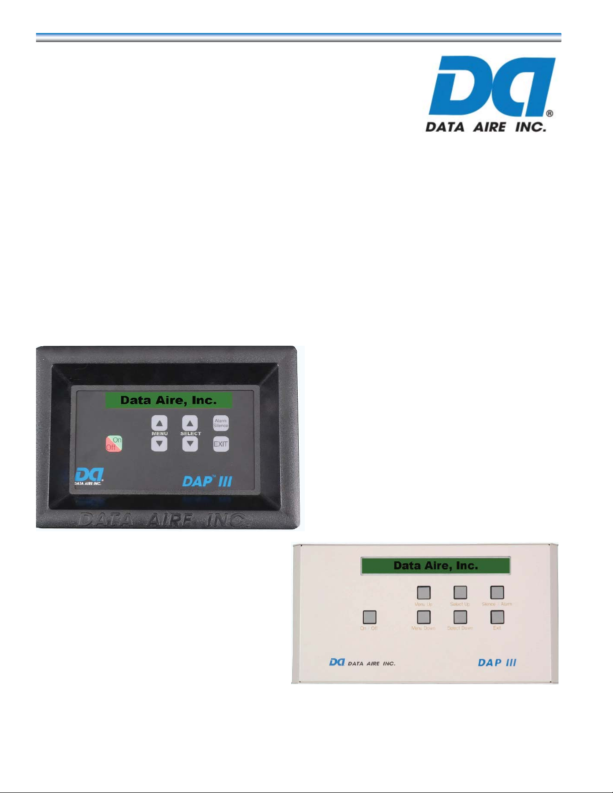
The unit mounted DAP III panel, shown to the left,
comes standard on all fl oor mount Data Aire units.
The wall mounted DAP III panel, shown to the right, is
standard on all Mini-Plus, LCS, and Shelf units. It can
also be an option on the Mini and fl oor mounted units.
While the DAP III has two distinct looks they are identical as far as program and function. This Operation Manual covers both the unit and wall mount.
4

Modes of Operation - The DAP III has two modes of operation. The Operation mode is the prevelant mode
and occurs when the unit is in normal operation. During this mode the top row of the display shows the current operation which the unit is in, such as: humidifi cation, dehumidifi cation, reheat stage - either 1,2 or 3 depending on how the
unit is confi gured; cooling stage - either 1 or 2 again depending on the confi guration of the unit; and energy saver. If
none of these condition exist a display of “Data Aire System Ready” will be shown. The lower row will continuously
scrolls through the following displays: date and time set in the DAP III program; unit number and zone number (Providing the unit is connected to a network. If not connected to a network it will display “N/A.”) as programmed; current
temperature and humidity detected by the return air sensors or if the optional remote sensors are used it will be the
conditions the remote sensors record; then any alarm conditions currently active. (A listing of these alarm conditions
are shown on page 11.) If your unit uses chilled water DAP III will display the percentage of chilled water fl ow as well.
In the upper right-hand corner of the DAP III display you should fi nd a blinking form in the shape of a heart. The blink-
ing indicates that the processor is functional.
The second mode of the DAP III is the Menu Mode which is described in the balance of this manual. To enter the
Menu Mode depress either of the MENU buttons.
DAP III Buttons - On the front of the DAP III there are seven buttons: an ON/OFF, MENU UP ()and MENU
DOWN () button; SELECT UP () and SELECT DOWN () button; SILENCE / ALARM button and an EXIT button.
The ON/OFF button is a soft power on/power off button. The hard power ON/OFF switch is located on the DAP III
Control Module circuit board and will be explained in the next section of this manual.
SILENCE /ALARM button only function is to mute audio alarms, the button is sparingly used in programming.
EXIT button has no function in the operation mode, however, it is used in the menu mode. Once in the menu mode
when the EXIT button is depressed the values programmed are saved and takes you up one level. For example if
you are in the Menu Groups, as shown on the top of page 13, depressing the EXIT button will take you to the operation mode. However, if you are in a Sub-Menus, shown on pages 13-15, depressing the EXIT button will take you to
the Menu Group for that sub group. For example if you were in sub-menu group 4-6 Firestat Temperature Alarm Limit,
depressing the EXIT button will take you to Menu Group 4 - Alarms .
MENU / MENU these buttons primarily allow you the scroll up or down in the menu grouping that you are in
currently. If you are in the Group menus depressing the MENU button will take you to the next higher menu, from
Group1 - Status & History to Group 2 - Setpoints. Conversely pressing the MENU button will take you to the next
lower menu in that grouping, from sub group 8-5 Set-Back Reheat depressing the MENU button would take you
to sub group 8-4 Set Up Cool. (All menu grouping continuously scroll, once you reach the last menu option and you
depress the MENU button you will return to the fi rst menu option.) These buttons have other specialized functions
depending on the subgroup menu you are addressing. These functions are described in the body of this manual in
the section where they apply. If the MENU buttons are held down they will advance at a rapid rate. If there is no button activity for three minutes the DAP III will return to the Operation Mode.
SELECT /SELECT these buttons, as the name implies, allows you to select a menu once you have located it
using the menu buttons. For example if you wanted to select the sub group menus for “Group 3 - Operation,” once
you scrolled to the group using menu buttons - depress the SELECT button will take you to “3-1 - Set Time and
Date,” the SELECT button would take you to sub menu “3-16 - Humidifi cation Desaturation Cycle” the last menu
option in sub-menu group 3 Once in sub group menus the SELECT and SELECT buttons permit you to scroll
through that menu’s options..
5

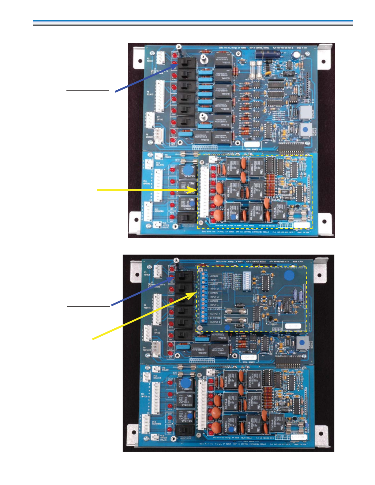
Hard Power ON/OFF Switch - After supplying power to the unit, if the DAP III does not come on when you
press the soft ON/OFF button on the cover of the DAP III it will be necessary for you to open the cover of the DAP III
The DAP III can be shipped in three different confi guration of circuit boards; the basic DAP III board; the DAP III with
the relay board; and DAP III with the relay and analog boards. Each of these confi gurations are shown below and on
the following page. The confi guration in your unit is dependent on the type of cooling and options that was selected.
One of these photos will match the circuit board that is in your unit. However the hard ON/OFF switch is in the same
position on all boards
DAP III Circuit Board
Control Module
Hard power ON/OFF Switch
Shown in the ON position
on the upper panel and OFF
position in the lower panel.
DAP III Control Module
Control Expansion Module
The use of the additional switches on the circuit boards will be discussed on page 7878 of this manual.
6
DAP III Circuit Board with Relay Module installed
Hard power ON/OFF Switch
shown here in the OFF
position
Relay Module
DAPIII CIrcuit Board with Relay and Analog Modules installed
Hard Power ON/OFF Switch
shown here in the OFF
position
Analog Module
7

DATA ALARM PROCESSOR – III
The Data Alarm Processor-III (DAP-III) offers the defi nite answer for precision environmental control. The DAP-III
control system not only controls and monitors temperature, humidity , airfl ow and cleanliness, it provides component run
times, alarm history and an automatic self-test of the microprocessor. All messages are presented in a clear simple
English and sequentially displayed on a backlit, liquid crystal display (LCD). The DAP-III can interface with a variety of
building management systems (BMS).
STANDARD FEATURES
Stand Alone Panel – Service terminals or additional devices are not required for programming or monitoring functions.
Microprocessor Based – State-of-the-art technology and reliability in a programmable solid-state control panel.
Smooth Keyboard Type Switches – High reliability, fl at, sealed switches with tactile feedback.
Two Row, 80 Character, Backlit Supertwist Liquid Crystal Display (LCD) – information is displayed and presented
in a format that is easily viewed and understood.
All Settings are Programmable from the face of the Panel – Expedient and user-friendly.
Layered Forward and Backward Menu Access – Facilitates programming with fl exible operation.
Multi-level Password Access– Controls any unauthorized changes to settings and system functions.
Database of Unit and Room Conditions – Historical data that facilitates service, apparatus setup and fi ne tuning of
setpoints.
Battery Backup for Historical Data – Extensive historical data is preserved by integral battery backup in case of power
failure.
Menus Factory Programmed – Menus that pertain to the type and method of cooling, reheat and humidifi cation based
on the unit’s components and options.
Programmed Settings Saved in Flash Memmory – Non-volatile memory stored so all control settings and operational
parameters are secured indefi nitely even during power outage.
Factory Calibrated Temperature and Humidity Sensors – Accurate and consistent regulation especially in multiple
unit applications.
Automatic Self-T est Diagnostics – Verifi es the processor and selected components are functioning properly at power
on and continuously during operation.
OPERATIONAL FEATURES
(Optional feature may require additional components and/or sensors.)
Sequential Load Activation – Time and temperature based logic that sequentially starts and stops stages of cooling
and reheat.
Compressor Short Cycle Control – Prevents excessive compressor wear by using restart and anti-cycle limits.
Automatic or Manual Restart – Restart methods are programmable in the event of a power failure.
8

Supplemental Compressor Operation during Energy Save Mode – Extends the savings from Energy Saver by
allowing one or two compressors to supplement cooling as needed when Energy Saver cooling is not suffi cient.
T emperature Anticipation – Responds to varying rates of temperature change.
Humidity Anticipation – Modifi es the humidity setpoint to diminish excess humidifi cation and dehumidifi cation.
Dehumidifi cation Mode Lockout – Inhibits dehumidifi cation if not required for system performance.
Start Time Delay – Programmable time delay staggers the start-up of multiple units to prevent high power demand
peaks.
Chilled Water, Energy Saver and Hot Water Coil Flush Cycle – Periodically circulates fl uid in the coil to reduce
deposit buildup in system.
Automatic Compressor Rotation – Periodically rotates the lead/lag sequence to balance compressor run times.
Automatic Reheat Element Rotation – Rotates the staging sequence to balance the run times of the heating elements.
Energy Saver (Glycol) or Auxiliary Chilled Water Operation – Two types of Energy Saver Systems are available.
Programmable Water Under Floor Alarm - Can shut down unit or just compressors.
DIAGNOSTIC AND SERVICE FEATURES
Alarms Displayed in Order of Occurence – Sequence with time of occurrence assist in diagnosing the cause of
alarms.
Programmable Delays for Optional Alarms – Reduces nuisance and false alarms caused by temporary or transient
conditions.
Manual Diagnostic Program – Provides accessible procedures to test the processor and major system components.
Manual Override for Blower, Cool 1 and 2, Heat 1, Humidifi cation and Water V alve – The control circuit is operable
even if the processor is not functioning properly.
Adjustable Alarm Limits – Threshold levels for temperature and humidity alarms are programmable.
Four Programmable Optional Alarms – In addition to the standard alarms, four additional alarms are programmable.
Select Alarms Optionally Disabled – Nonessential alarms can be turned off.
Audio Alarm Tone – Four programmable alarm tones.
PROTECTIVE AND SAFETY FEATURES
Metal Shell Enclosure with Sealed Front Control Panel – Provides electromagnetic interference (EMI) protection and
general protection against environmental contamination and handling damage.
Watch Dog Timer – Automatically resets the circuit board, clears any corrupted memory and restarts the system with
minimal interruption in case of an unfi ltered transient signal.
Opto-Signal Inputs – Isolates the circuit board from electrical noise or static from contactors, compressors and motors
that can contaminate the power at the circuit board.
9

Protected 24 V AC Power Input – Fused metal oxide varistor (MOV) and transient voltage suppressor react to interrupt
the power from the circuit board if excessive amperage or over voltage condition is detected.
Isolation Transformer – Protection against ground loops, ground shorts, wiring errors and conducted electrical
interference.
Heavy Ground Planes and Power Foils – Large ground plane areas and wide power runs minimize disturbances
caused by EMI and other types of electrical interference.
Switching Power Supply – Allows for wide AC input voltage fl uctuation to reduce the effects of a power blackout while
still maintaining circuit board operation.
Fused RS-485 Network Lines on Network Communication Card – Disconnects the circuit board from the source of
current to protect the circuit board components.
Modulating Humidifi er Control – Proportional control of steam generator humidifi er provides additional refi nements in
performance. (Optional Relay Module required.)
Humidifi er Autofl ush Cycle – An adjustable fl ush cycle for infrared humidifi ers to reduce deposit build-up. (Optional
Relay Module required.)
Three Additional Remote Alarms – Group or specifi c alarm selection for remote alarm contact. (Optional Relay
Module required.)
Analog Inputs – Output values of four external analog sensors can be read on the processor display . (Optional Analog
board required.)
Underfl oor Water Detection Cable – Provides continuous water detection cable to encircle the entire unit.
Display Panel
CONDITIONS and DATA DISPLAYED
TEMPERATURE SETPOINT – ºF or ºC CURRENT TEMPERATURE – ºF or ºC
HUMIDITY SETPOINT – Percent of relative humidity CURRENT HUMIDITY – Percent of relative humidity
CURRENT DISCHARGE AIR or CHILLED WATER TEMPERATURE* - ºF or ºC
FUNCTIONS DISPLAYED
COOLING – 1st stage, 2nd stage, 3rd stage*, 4th stage* REHEAT – 1st stage, 2nd stage, 3rd stage, hot water*
CHILLED WATER FLOW – 10 to 100% (based on VDC output) ENERGY SAVER* - hours of operation
DEHUMIDIFICATION - hours of operation HUMIDIFICATION - hours of operation
* This optional feature or data display may require additional components and/or sensors.
10

WARNING AND ALARMS DISPLAYED
HIGH TEMPERATURE WARNING – (Current temperature)º F/C HIGH HUMIDITY WARNING – (Current RH)%
LOW TEMPERATURE WARNING – (Current temperature)º F/C LOW HUMIDITY WARNING – (Current RH)%
LOW PRESSURE COMPRESSOR: 1 – (Automatic reset) NO AIRFLOW – CHECK BELT AND MOTOR
UNDER FLOOR WATER DETECTION – CHECK PROBE DIRTY FILTER – CHECK FILTERS
LOW PRESSURE COMPRESSOR: 2 – (Automatic reset) POWER FAILURE RESTART
MANUAL OVERRIDE – CHECK BYPASS SWITCHES FIRESTAT TRIPPED – Unit shutdown
HUMIDIFIER PROBLEM – CHECK WATER PRESSURE LOW VOLTAGE WARNING – CHECK VOLTAGE
TEMPERATURE SENSOR ERROR – SENSOR PROBLEM COMPRESSOR SHORT CYCLE – WARNING
MAINTENANCE REQUIRED LOCAL ALARM – SEE TAG INSIDE
HUMIDITY SENSOR FAILURE – SENSOR PROBLEM NO WATER FLOW* - CHECK WATER PUMP
CUSTOM MESSAGE – (Factory programmed custom message) SMOKE DETECTOR* - Unit shutdown
DISCHARGE AIR SENSOR ERROR* HIGH CONDENSATE WATER LEVEL*
FAN MOTOR OVERLOAD* – CHECK MOTOR AMPERAGE
STANDBY PUMP ON* - CHECK PRIMARY WATER PUMP
PERSON TO CONTACT ON ALARM* - (Programmable message)
HIGH PRESSURE/INTERNAL OVERLOAD COMPRESSOR: 1 - Manual reset required
HIGH PRESSURE/INTERNAL OVERLOAD COMPRESSOR: 2 - Manual reset required
HISTORICAL DATA DISPLAYED
EQUIPMENT RUNTIMES – Blower, compressor 1 and 2, reheat strip 1, 2, and 3, dehumidifi cation, Energy Saver*,
humidifi er, condenser and chilled water
ALARM HISTORY – Last 10 alarms with time and date of occurrence
LAST 24 HOURS – High and low temperature, high and low humidity
AVERAGE PERCENT OF CAPACITY LAST HOUR – Compressor(s), humidifi er, reheat strips and water valve
* This optional feature or data display may require additional components and/or sensors.
11

PROGRAMMABLE SELECTIONS
Temperature setpoint Temperature deadband
High temperature alarm limit Low temperature alarm limit
Humidity setpoint Humidity deadband
High humidity alarm limit Low humidity alarm limit
Mode and stage response time Compressor lead/lag sequence
Reset equipment runtimes Audio alarm mode
Automatic self-test acknowledgement Manual diagnosis
Humidity anticipation Compressor short cycle alarm
Dehumidifi cation mode Low discharge temperature alarm limit*
Power problem or restart mode System start delay
Message for optional alarm 1, 2, 3, and 4* Delay for optional alarm 1, 2, 3, and 4
Compressor supplements to energy saver* Remote alarm 1, 2, 3 and 4 selection*
Person to contact on alarm Defi ne password
Humidifi er autofl ush timer* Firestat temperature alarm limit
Scheduled normal maintenance Temperature scale
Calibrate temperature sensor Calibrate humidity sensor
Compressor(s) Reheat states
Humidifi er Water valve mode
Water valve voltage range Reverse acting water valve
Network protocol* Analog module sensor setups*
Fan speed control module*
Calibrate discharge air sensor or chilled water temperature sensor*
- May require optional modules
*
12

MENU GROUPS
Group 1 – Status and History Group 6 – Network
Group 2 – Setpoints Group 7 – Calibration
Group 3 – Operation Group 8 – Set-back**
Group 4 – Alarms Group 9 – Diagnostics
Group 5 – Confi guration Group 10 – Analog*
Gruop 11 – Zone Conrol
SUB-MENUS
Group 1 – Status and History
1-1 Temperature and humidity setpoints
1-2 Last 24 hours temperature and humidity
1-3 Percent capacity and average last hour
1-4 Equipment runtimes
1-5 Alarm history-clear alarm history
MENU GROUPS 2 THROUGH 11 REQUIRE A PASSWORD ENTRY
Group 2 – Setpoints
2-1 Change temperature setpoints
2-2 Change temperature deadband
2-3 Change humidity setpoint
2-4 Change humidity deadband
2-5 Change cooling stage-to-stage DB (deadband)
2-6 Change E-Saver CW (chilled water) temperature SP (setpoint)
2-7 Change E-Saver CW temperature DB
Group 3 – Operation
3-1 Set time and date
3-2 Mode and stage response time
3-3 Compressor lead/lag sequence
3-4 System start delay
3-5 Reset equipment run time
3-6 Automatic self-test acknowledge
3-7 Compressor supplements to E-Saver
3-8 Energy Saver lock-out time
3-9 Dehumidifi cation mode
3-10 Power problem or restart mode
3-11 Scheduled normal maintenance
3-12 Temperature scale
3-13 Fan mode*
3-14 Override request
3-15 Humidity anticipation
3-16 Humidifi cation desaturation cycle
3-17 Energy Saver to DX change over deadband
3-18 Constant fan speed for DX cooling
3-19 Constant fan speed for CW cooling
3-20 Fan speed control for DX cooling
3-21 Fan speed control for CW cooling
3-22 Maximum fan speed
3-23 Minimum fan speed
3-24 Differential pressure setpoint
3-25 Differential pressure deadband
3-26 Fan speed response rate
* Only displays when analog module is connected.
** Only displays when DAP III is in RFM (reduced function mode) ceiling systems.
13

SUB-MENUS- continued
Group 4 – Alarms
4-1 Audio alarm mode
4-2 Change high temperature alarm limit
4-3 Change low temperature alarm limit
4-4 Change hi humidity alarm limit
4-5 Change lo humidity alarm limit
4-6 Firestat temperature alarm limit
4-7 Low discharge temp alarm limit
4-8 Compressor short-cycle alarm
4-9 Water under fl oor alarm action
4-10 No water fl ow alarm action
4-11 Person to contact on alarm
4-12 Message for optional alarm input 1
4-13 Delay for opt. alarm input 1
4-14 Message for opt. alarm input 2
4-15 Delay for opt. alarm input 2
4-16 Message for opt. alarm input 3
4-17 Delay for opt. alarm input 3
4-18 Message for opt. alarm input 4
4-19 Delay for opt. alarm input 4
4-20 Remote alarm number 1 selection
4-21 Remote alarm number 2 selection
4-22 Remote alarm number 3 selection
4-23 Remote alarm number 4 selection
4-24 No airfl ow alarm time delay
4-25 No water fl ow alarm time delay (locked)
MENU GROUP 5 IS LOCKED – NO CHANGES CAN BE MADE UNTIL
MENU IS UNLOCKED
Group 5 – Confi guration
5-1 Sensor location
5-2 Defi ne password
5-3 Reduced Function Mode (RFM) active
5-4 Compressor(s)
5-5 Reheat stage
5-6 Humidifi er
5-7 Water valve mode
5-8 Water valve voltage control range
5-9 Reverse acting water valve
5-10 Humidifi er autofl ush timer Only displays when infared humidifi er installed
Group 6 – Network
6-1 Unit and network ID
6-2 Network protocol
6-3 IP address
6-4 Netmask address
6-5 Router address
6-6 UDP port
6-7 Ethernet TCP port
6-8 Baudrate (Only appear when ModBusRTU, Modbus ASCII, BACnet MS/TP and
Johnson Control N2 protocol is selected. Requires RS-485 communications card.)
6-9 Network ID
6-10 Device ID (this menu only shows when BACnet MS/TP or BACnet Master is selected)
6-11 Max Master (This menu only shows when BACnet MS/TP is selected.)
Menus 6-12 through 6-15 only appear when SNMPv1/v2 is selected.
Shaded menus only displayed when
Ethernet card is installed and confi gured
for Bacnet IP, MODBUS TCP or SNMP
14

6-12 SNMPv2 Manager 1 Address
6-13 SNMPv2 Manager 1 Notifi cations
6-14 SNMPv2 Manager 2 Address
6-15 SNMPv2 2 Notifi cations
Group 7 – Calibration
7-1 Calibrate temperature sensor
7-2 Calibrate humidity sensor
7-3 Calibrate discharge air temperature sensor
7-4 Calibrate CW temperature sensor
Group 8 – Setback
(Only displayed when RFM mode is active.)
8-1 Day schedule
8-2 Override enable
8-3 Override time
8-4 Setup cool
8-5 Setback reheat
8-6 Setup dehumidifi cation
8-7 Setback humidifi cation
8-8 Monday schedule
8-9 Tuesday schedule
8-10 Wednesday schedule
8-11 Thursday schedule
8-12 Friday schedule
8-13 Saturday schedule
8-14 Sunday schedule
Group 9 – Diagnostic
9-1 Test buttons
9-2 Check power supply
9-3 Test relays
9-4 Test analog outputs
9-5 Test digital inputs
9-6 Test environmental sensors
9-7 View anticipation humidity setpoint
9-8 Test audio alarm
9-9 Test RS-485 network card
9-10 Test watchdog reset circuit
Group 10 – Analog Group 10 - (Only appears when an Analog Module is connected.)
10-1 Select sensor 1 name
10-2 Specify sensor 1 units of measure
10-3 Specify sensor 1 signal range
10-4 Specify sensor 1 minimum value
10-5 Specify sensor 1 maximum value
10-6 Set Sensor 1 calibration
10-7 Select sensor 2 name
10-8 Specify sensor 2 units of measure
10-9 Specify sensor 2 signal range
10-10 Specify sensor 2 minimum value
10-11 Specify sensor 2 maximum value
10-12 Set sensor 2 calibration
10-13 Select sensor 3 name
10-14 Specify sensor 3 units of measure
10-15 Specify sensor 3 signal range
10-16 Specify sensor 3 minimum value
15

10-17 Specify sensor 3 maximum value
10-18 Set sensor 3 calibrations
10-19 Select sensor 4 name
10-20 Specify sensor 4 units of measure
10-21 Specify sensor 4 signal range
10-22 Specify sensor 4 minimum value
10-23 Specify sensor 4 maximum value
10-24 Set sensor 4 calibration
10-25 Select output 1 confi guration
10-26 Select output 2 confi guration
Group 11 - Zone Control
11-1 Zone mast enable
11-2 Zone ID
11-3 Unit IDs in this zone
11-4 Primary unit status
11-5 Secondary unit status
11-6 Zone override request
11-7 Unit rotation day
11-8 Unit rotation time
11-9 Standby alarms
11-10 Off alarm
11-11 Temperature standby
11-12 Zone inhibits
11-13 Secondary schedule
11-14 Secondary schedule start day
11-15 Secondary schedule start time
11-16 Secondary schedule stop day
11-17 Secondary schedule stop time
16

PUSH BUTTON FUNCTIONS
The Data Alarm Processor-III panel has seven pressure sensitive feedback-type buttons on the face of the panel. All
programming functions and/or settings are done from the face of the panel. Their functions are as follows:
Menu - Advances the menus
in ascending order
from 1 to 10
ON/OFF - Soft switch that
turns the power on
or off to the microprocessor
Select - Selects an option or value in
ascending order.
ALARM SILENCE
Silences the audio alarm
Menu - Advances the menus
in descending order
from 10 to 1.
Select - Selects an option or value
in descending order
EXIT - Saves the new settings,
exits the menu function
and returns the panel
to its normal operating
mode
IMPORTANT NOTE:
The RAM SIGNATURE test often displays “FAIL” on initial start-up because the RAM does not have any stored data.
Simply press “SELECT” to bypass the “FAIL” message. Once the processor is on-line and operating, the RAM will
collect data and the test should pass on future restarts. On start-up, remember to remove the protective paper on the
battery before turning the unit on. Otherwise, the RAM SIGNATURE will fail on future restarts.
Each time a MENU or SELECT button is pressed, it will advance to the next menu, sub-menu, or selection. If the button
is held down, the menus or selections will advance at a rapid rate. If there is no button activity for three (3) minutes the
panel will return to its normal operating mode.
When a menu fi rst appears, it will have a menu number and title. The fi rst time a SELECT button is pressed, the current
value or option in memory is displayed. Additional pressing of a SELECT button will cause alternate values, options
or selections to be displayed. The SELECT button should be pressed until the desired value, option or selection is
displayed. After the desired value, option or selection has been chosen, the MENU button is pressed to save the last
displayed entry into memory and to advance to the next menu display. The EXIT button can be pressed at any time
to return the panel to its normal operating mode. In this mode, the panel will scroll and display the current system
functions, temperature, humidity and ID number. If an alarm is present it will also be displayed.
17

AUTOMATIC DIAGNOSTIC SELF-TEST - ON START UP
Press the power ON button to energize the panel. The following messages will be displayed as the panel proceeds through the
Automatic Diagnostic Self-Test. The Automatic Diagnostic Self-Test takes approximately 30 seconds.
Display Message 1
DATA ALARM PROCESSOR III
MODEL xxx-xxx-xxx BOOTLOADER REV x.xx
Display Message 2
DATA ALARM PROCESSOR III
MODEL nnn-nnn-nnn SOFTWARE REV; n.nn
Display Message 3*
DATA ALARM PROCESSOR III
MODEL nnn-nnn-nnn CONTROL MODULE
Display Message 4*
DATA ALARM PROCESSOR III
MODEL nnn-nnn-nnn EXPANSION MODULE
Display Message 5*
DATA ALARM PROCESSOR III
MODEL nnn-nnn-nnn RELAY MODULE
Display Message 6*
DATA ALARM PROCESSOR III
MODEL nnn-nnn-nnn ANALOG MODULE
Display Message 7*
DATA ALARM PROCESSOR III
MODEL nnn-nnn-nnn (Comm Card) MODULE
Display Message 8
DATA ALARM PROCESSOR III SELF-TEST
FLASH: PASS
Display Message 9
DATA ALARM PROCESSOR III SELF-TEST
STATIC RAM: PASS
Display Message 10
DATA ALARM PROCESSOR III SELF-TEST
PARAMETERS: PASS
Display Message 11
DATA ALARM PROCESSOR III SELF TEST
RAM SIGNATURE: PASS
Display Message 12
DATA ALARM PROCESSOR III SELF-TEST
ANALOG: PASS
Display Message 13
DATA ALARM PROCESSOR III SELF-TEST
12 VDC REGULATED: nn.n PASS
Display Message 14
DATA ALARM PROCESSOR III SELF-TEST
5VDC REGULATED: nn.n PASS
Display Message 15
DATA ALARM PROCESSOR III SELF-TEST
BATTERY VOLTAGE: n.n PASS
Display Message 16
DATA ALARM PROCESSOR III SELF-TEST
RETURN TEMP SENSOR: PASS
Display Message 17
DATA ALARM PROCESSOR III SELF-TEST
DISCHARGE TEMP SENSOR: PASS
Display Message 18
DATA ALARM PROCESSOR III SELF-TEST
HUMIDITY SENSOR: PASS
Display Message 19
DATA ALARM PROCESSOR III SELF-TEST
BUTTONS: PASS
If there is a failure during the
Automatic Self-Test, the display will
stop scrolling and only the message
with the failure will be displayed.
To allow the processor to continue
the self-test after a failure has been
displayed, press the MENU button.
See Menu 3-6 Automatic Self-Test
Acknowledge toggle. When the
self-test is complete, the timed Start
Delay will be displayed.
Display Message
DATA ALARM PROCESSOR III
START DELAY: mm:ss
After the timed start delay is
complete, the unit will start and
the processor will be in operating
mode. The following pages are
typical displays for each menu, with
available selections, options and/
or values. Factory settings are also
listed.
* Only displays when these modules or
communication cards are connected.
18

MENUS
There are 10 MENU groups. Each group has a sub-set (SUB-MENUS). The following describes how to navigate
through the MENUS and SUB-MENUS:
Group 1
NOTE: GROUP 1 SUB-MENUS ARE READ ONLY. CHANGES CANNOT BE MADE.
To Access:
MENU - The display will read GROUP 1 – STATUS & HISTORY
SELECT - 1-1 TEMPERATURE & HUMIDITY SETPOINTS
SELECT - Display will read: TEMPERATURE SEPOINT IS: xxF (or C)
SELECT - Display will read: HUMIDITY SEPOINT IS: xx%
(Pressing the SELECT or button will alternately change the display reading from TEMPERATURE
to HUMIDITY, HUMIDITY to TEMPERATURE )
MENU - Display will read: 1-2 LAST 24 HRS TEMPERATURE & HUMIDITY
SELECT - To read current temperature and range over the last 24 hours
Display will read: TEMPERATURE: xxF (or C) LAST 24 HOURS: xx-xxF (or C)
SELECT - To read current humidity and range over the last 24 hours
Display will read: HUMIDITY: xx% LAST 24 HOURS: xx-xx%
MENU - Display will read: 1-3 PERCENT CAPACITY & AVERAGE LAST HR
SELECT - Display will read: COMPRESSOR: xxx% LAST HR AVERAGE: xxx%
SELECT - Display will read: REHEAT: xxx% LAST HR AVERAGE: xxx%
SELECT - Display will read: HUMIDIFIER: xxx% LAST HR AVERAGE: xxx%
SELECT - Display will read: WATER VALVE: xxx% LAST HR AVERAGE: xxx%
MENU - Display will read: 1-4 EQUIPMENT RUNTIMES
SELECT - Display will read: BLOWER: xxxx HOURS
SELECT - Display will read: HEAT EXCHANGER: xxxx HOURS
SELECT - Display will read: COMPRESSOR 1: xxxx HOURS
SELECT - Display will read: COMPRESSOR 2: xxxx HOURS
19

SELECT - Display will read: COMPRESSOR 3: xxxx HOURS
SELECT - Display will read: COMPRESSOR 4: xxxx HOURS
SELECT - Display will read: REHEAT STRIP 1: xxxx HOURS
SELECT - Display will read: REHEAT STRIP 2: xxxx HOURS
SELECT - Display will read: REHEAT STRIP 3: xxxx HOURS
SELECT - Display will read: HUMIDIFIER: xxxx HOURS
SELECT - Display will read: DEHUMIDIFICATION: xxxx HOURS
SELECT - Display will read: ENERGY SAVER COOLING: xxxx HOURS
SELECT - Display will read: CHILLED WATER COOLING: xxxx HOURS
MENU - Display will read: 1-5 ALARM HISTORY-CLEAR ALARM HISTORY
SELECT - Display will read:
ALARM HISTORY hh:mm mm-dd-yy (time and date of alarm)
ALARM MESSAGE
(Alarm messages are displayed in order of occurrence: last alarm fi rst then other alarms in most recent
sequence. Up to 10 messages are stored in memory)
Alarm history can be cleared. Press SELECT button until the display shows
USE SILENCE BUTTON TO CLEAR HISTORIES
Pressing the SILENCE/ALARM button will clear alarms.
SELECT - To view the past ten alarm messages.
EXIT - Display will read: GROUP 1 – STATUS & HISTORY
NOTE: MENU groups 2 thru 11 require password entry, once a password has been set.
The correct password will allow the user to set/change all sub-menus in Groups 2 through 11. It will also allow the
user to view all factory locked menus (Sub menu 4-24, Group 5 – Confi guration and portions of Group 6 - Network).
To access the factory locked menus, a specifi c button sequence is required. Neither the password nor the button
sequence will be required again until the user has exited from the menus to operation mode, either by pressing the
EXIT button or by allowing three (3) minutes to elapse with no button activity. FOR LOCKED MENU ACCESS – SEE
PROCEDURES TO UNLOCK GROUP 5 MENUS. DAP-III panels are shipped with the password set at 00, indicating
no password set. If a password has been set and is unknown, the number 40 can be entered to allow viewing access
to sub-menus 2-10. 40 should never be used as a defi ned password. This is a temporary bypass to allow verifi cation
of the programmed password and will be deleted when the EXIT button is pressed or when three (3) minutes has
elapsed without button activity.
MENU Display will read: ENTER PASSWORD FOR ADDITIONAL MENUS
PASSWORD: nn
SELECT or - To select password to proper value (00 to 99)
20

NOTE: If the wrong password is entered, the display will read
WRONG PASSWORD DELAY 60 SECONDS
CURRENT OPERATING FUNCTIONS & STATUS DISPLAY.
The message will continue to display for 60 seconds. At the end of 60 seconds the display will return to
Display will read: GROUP 1 – STATUS & HISTORY
Group 2
MENU - Display will read: GROUP 2 – SETPOINTS
SELECT - To see SUB-MENU 2-1: CHANGE TEMPERATURE SETPOINT
Display will read: 2-1 CHANGE TEMPERATURE SETPOINT
SELECT or - To display current temperature setpoint
Display will read: 2-1 CHANGE TEMPERATURE SETPOINT
SET AT: nnF
SELECT or - To scroll to desired temperature setpoint in 1º increments.
(Temperature setpoint is adjustable from 65 to 85º F/18.3 to 29.4º C. Factory setting is 72º F / 22.2º C)
To save setting and return to Menu Group 2 depress EXIT button or
MENU - To display SUB-MENU 2-2: CHANGE TEMPERATURE DEADBAND
Display will read: 2-2 CHANGE TEMPERATURE DEADBAND
SELECT or - To display current temperature deadband.
Display will read: 2-2 CHANGE TEMPERATURE DEADBAND
SET AT: n.nF
SELECT or - To scroll to desired setting.
(Temperature deadband is adjustable ± 1 to 5º F/C in 0.1º increments. Factory setting is 2.0º F. / -16.7º C)
To save setting and return to Menu Group 2 depress EXIT button or...
MENU - To display SUB-MENU 2-3: CHANGE HUMIDITY SETPOINT
Display will read: 2-3 CHANGE HUMIDITY SETPOINT
SELECT or - To display current humidity setpoint.
Display will read: 2-3 CHANGE HUMIDITY SETPOINT
SET AT: nn%
SELECT or - Scroll to desired setting in 1% increments.
(Humidity setpoint is adjustable from 25 to 70% RH. Factory setting is 50%.)
MENU - To display SUB-MENU 2-4: CHANGE HUMIDITY DEADBAND
Display will read: 2-4 – CHANGE HUMIDITY DEADBAND
21

SELECT or - To display humidity deadband.
Display will read: 2-4 CHANGE HUMIDITY DEADBAND
SET AT: nn.n%
SELECT or - Scroll to desired setting, in 0.1% increments.
(Humidity deadband is adjustable from 1.0 – 15.0% relative humidity. Factory setting is 3.0%.)
MENU - To display SUB-MENU 2-5: CHANGE COOLING STAGE-TO-STAGE DB
Display will read: 2-5 CHANGE COOLING STAGE-TO-STAGE DB
SELECT or - To view cooling stage-to-stage deadband.
Display will read: 2-5 CHANGE COOLING STAGE-TO-STAGE DB
SET AT: n.nF
SELECT or - Scroll to desired setting, in 0.1º increments.
(Cooling stage-to-stage deadband is adjustable from 0.3 to 3.0ºF / -17.6 to -16.1ºC. Factory setting is 0.3º F/C.)
MENU - To display SUB-MENU 2-6:CHANGE E-SAVER CW TEMPERATURE SETPOINT
Display will read: 2-6 – CHANGE E-SAVER CW TEMPERATURE SP
SELECT or - To view current E-SAVER CW temperature setpoint.
Display will read: 2-6 – CHANGE E-SAVER CW TEMPERATURE SP
ENERGY SAVER AVAILABLE AT nn F
SELECT or - Scroll to desired setting, in 1º increments.
(Energy Saver CW temperature setpoint is adjustable from 40 to 60ºF / 4.4 to 15.6ºC Factory setting is 50ºF/C)
MENU - To display SUB-MENU 2-7: CHANGE E-SAVER CW TEMPERATURE DEADBAND
Display will read: 2-7 – CHANGE E-SAVER CW TEMPERATURE DB
SELECT or - To view E-SAVER CW temperature deadband.
Display will read: 2-7 – CHANGE E-SAVER CW TEMPERATURE DB
SET AT n.nF
SELECT or - To scroll to desired setting, in 1º increments.
(Energy Saver CW temperature deadband is adjustable 1.0 to 5.0ºF/ -17.2 to -15ºC. Factory setting is 1.0ºF/C)
EXIT - Press EXIT to return to GROUP 2 - Setpoints
EXIT - Press EXIT again to return to operational mode.
OR
22

Group 3
MENU - Display will read: GROUP 3 - OPERATION
SELECT - Display will read: SET TIME AND DATE
SELECT - To change time and date
Display will read: 3-1 SET TIME AND DATE
SET WEEKDAY:
SELECT or - To change current weekday.
MENU - To change month.
Display will read: 3-1 SET TIME AND DATE
SET MONTH: day mm-dd-yy hh:mm
SELECT or - To change the month.
MENU - To change day.
Display will read:
3-1 SET TIME AND DATE
SET DAY: day mm-dd-yy hh:mm
day mm-dd-yy hh:mm
SELECT or - To change day.
MENU - To change year
Display will read:
3-1 SET TIME AND DATE
SET YEAR: day mm-dd-yy hh:mm
SELECT or - To change year.
MENU - To change hour.
Display will read:
3-1 SET TIME AND DATE
SET HOUR: day mm-dd-yy hh:mm
SELECT or - To change the hour.
MENU - To change minute.
Display will read:
3-1 SET TIME AND DATE
SET MINUTE: day mm-dd-yy hh:mm
SELECT or - To change the minutes.
EXIT - Display will read: 3-1 SET TIME AND DATE SETTING TIME – PLEASE WAIT
23

MENU - To display SUB-MENU 3-2: MODE AND STAGE RESPONSE TIME
Display will read: 3-2 MODE & STAGE RESPONSE TIME
The MODE AND STAGE RESPONSE TIME is a time-based differential over which the processor does not
respond to any changes in temperature or humidity. This includes different functions as well as staging of
individual functions.
SELECT - To display current setting
Display will read:
3-2 MODE & STAGE RESPONSE TIME
RESPONSE TIME: n MINUTE
SELECT or - To change current setting
(Mode and Stage Response Time is adjustable 1 to 5 minutes, in 1 minute increments. Factory setting is
1 minute. Test mode is also an available setting. T est mode allows immediate movement from one function
to another without delay. This should only be used during testing and not left as a operational setting)
MENU - To view SUB-MENU 3-3: COMPRESSOR LEAD/LAG SEQUENCE
Display will read: 3-3 COMPRESSOR LEAD/LAG SEQUENCE
SELECT - To display current setting
Display will read:
3-3 COMPRESSOR LEAD/LAG SEQUENCE
LEAD/LAG SEQUENCE: AUTOMATIC
For the menu item there are three selections:
AUTOMATIC - Changes lead compressors every 168 hours.
1 LEAD
2 LEAD
SELECT or - To change current setting
Factory setting is AUT OMATIC on dual compressor units. In Automatic mode the compressor lead/lag
sequence will change lead compressor every 168 hours of operation.
MENU - To view SUB-MENU 3-4: SYSTEM START DELAY
System Start Delay provides programmable start delay to minimize total in rush current
with multiple unit applications.
Display will read: 3-4 SYSTEM START DELAY
SELECT or - To change current setting
Display will read:
3-4 SYSTEM START DELAY
UNIT STARTS mm:ss AFTER POWER ON
Start delay ranges from 5 seconds to 10 minutes in 5 second intervals. Each time the select button is
pressed the delay will change by 5 seconds.
Factory setting is: 00:05
24

MENU - To view SUB-MENU
3-5: RESET EQUIPMENT RUNTIMES
SELECT - Display will read:
3-5 RESET EQUIPMENT RUNTIME
BLOWER: nnnn HOURS
Continue to press SELECT button to scroll thru the list. The following can be viewed:
CONDENSER: REHEAT STRIP 3:
COMPRESSOR 1: HUMIDIFIER:
COMPRESSOR 2: DEHUMIDIFICATION:
COMPRESSOR 3: ENERGY SAVER COOLING:
COMPRESSOR 4: CHILLED WATER COOLING:
REHEAT STRIP 1: RESET ALL TO ZERO RUNTIMES
REHEAT STRIP 2:
NOTE: Any component can be changed to zero hours. When viewing, press the SILENCE
button to reset a selection to zero hours. To reset all values scroll to the, “RESET ALL TO ZERO
RUNTIMES” menu selection and press the MENU or .
MENU - To view SUB-MENU 3-6: AUTOMATIC SELF-TEST ACKNOWLEDGMENT
If the Self-T est Acknowledge is programmed to “ON”, it will permit the processor to proceed through
the Diagnostic Self-Test even if a failure is detected without pressing the MENU button. It will
allow the unit to start.
SELECT - To view current mode
Display will read: AUTOMATIC SELF-TEST ACKNOWLEDGE: ON
OR
AUTOMATIC SELF-TEST ACKNOWLEDGE: OFF
SELECT or - To change the setting from ON to OFF or OFF to ON.
Factory setting is: OFF
NOTE: After startup,
the service technician should set submenu 3-6 to ON.
MENU - To view SUB-MENU 3-7 COMPRESSOR SUPPLEMENTS TO E-SAVER
Allows selection of simultaneous Energy Saver and compressor operation. (Optional discharge air
sensor is required.)
SELECT - To view current mode
Display will read: 3-7 COMPRESSOR SUPPLEMENTS TO E-SAVER
ENERGY SAVER NOT AVAILABLE
or SUPPLEMENT E-SAVER WITH 1 COMPRESSOR
or
or
SUPPLEMENT E-SAVER WITH 2 COMPRESSORS
SUPPLEMENT ENERGY SAVER WITH NO COMPRESSORS
SELECT or - To change current setting
Factory setting is: SUPPLEMENT ENERGY SAVER WITH TWO COMPRESSORS
25

NOTE: If the optional discharge air sensor is not installed, the display will read:
DISCHARGE TEMP SENSOR NOT INSTALLED
MENU - To view SUB-MENU 3-8 ENERGY SAVER LOCK-OUT TIME
Display will read: 3-8 ENERGY SAVER LOCK-OUT TIME
SELECT - To view current mode
Display will read: 3-8 ENERGY SAVER LOCK-OUT TIME
LOCKOUT TIME: nn MINUTES
SELECT or - To change current setting
Factory setting is 15 minutes. Lockout time is adjustable from 15 to 60 minutes in 15 minute increments.
MENU - To view SUB-MENU 3-9 DEHUMIDIFICATION MODE
Allows selection for number of compressors to be used in dehumidifi cation mode and temperature or
dehumidifi cation controlled priority.
Display will read: 3-9 DEHUMIDIFICATION MODE
SELECT or - To view current setting
Display will read: 3-9 DEHUMIDIFICATION MODE and one of the following messages:
DEHUMIDIFICATION OFF
or 1 COMPRESSOR & WITHIN REHEAT LIMITS
or 2 COMPRESSORS & WITHIN REHEAT LIMITS
or 1 COMPRESSOR & NO REHEAT LIMITS
or 2 COMPRESSORS & NO REHEAT LIMITS
NOTE: Unit supplied without reheat will display the following message:
NO REHEAT, DEHUMIDIFICATION NOT ALLOWED
SELECT or - To change current setting.
Factory setting is: DEHUMIDIFICATION MODE IS:
1 COMPRESSOR & WITHIN REHEAT LIMITS
MENU - To view SUB-MENU 3-10: POWER PROBLEM OR RESTART MODE
Display will read: 3-10 POWER PROBLEM OR RESTART MODE
SELECT or - To view current setting
Display will read: 3-10 POWER PROBLEM OR RESTART MODE
AUTOMATIC: NO MESSAGE OR ALARM
or AUTOMATIC: MESSAGE, AUDIO ALARM & RELAY
or MANUAL: MESSAGE, AUDIO ALARM & RELAY
Factory setting is: AUTOMATIC: NO MESSAGE OR ALARM
NOTE: If set for MANUAL, the unit must be MANUALLY RESTARTED after a power outage.
26

MENU - To view SUB-MENU 3-11: SCHEDULED NORMAL MAINTENANCE
Display will read: 3 - 11 SCHEDULED NORMAL MAINTENANCE
SELECT or - To view current setting
Display will read: 3 - 11 SCHEDULED NORMAL MAINTENANCE
MAINTENANCE DUE MESSAGE: OFF
or MAINTENANCE DUE MESSAGE EVERY: nnn HRS
Maintenance can be scheduled from 1 to 1000 hours in 1 hour increments.
SELECT or - To entry number of hours.
Factory setting is: MAINTENANCE DUE MESSAGE: OFF
MENU - To view SUB-MENU 3-12: TEMPERATURE SCALE
Display will read: 3 - 12 TEMPERATURE SCALE
SELECT or - To view current setting
Display will read: 3 - 12 TEMPERATURE SCALE
DISPLAY TEMPERATURE IN: FAHRENHEIT
SELECT or - To change current setting
There are two choices: Fahrenheit and Centigrade
Factory setting is: Fahrenheit
MENU - To view SUB-MENU 3-13: FAN MODE - This submenu does not display when RFM is OFF
his submenu does not display when RFM is OFF
Display will read: 3 - 13 FAN MODE
SELECT or - To view current setting
Display will read: 3- 13 FAN MODE
FAN MODE: CONTINUOUS
SELECT or - Change setting, options are:
CONTINUOUS (Fan runs continuously.)
or AUTO (Fan runs only when there is a call for cooling, heating, humidifi cation or
dehumidifi cation. Auto is only used in RFM mode, primarily ceiling applications.)
Factory setting is: CONTINUOUS
MENU - To view SUB-MENU 3-14: OVERRIDE REQUEST (When unit is in night setback mode and
you want the unit operating.)
Display will read: 3- 14 OVERRIDE REQUEST
SELECT or - To view current setting
Display will read: 3 - 14 OVERRIDE REQUEST
OVERRIDE REQUEST: NO
MENU - To view SUB-MENU 3-15: HUMIDITY ANTICIPATION
27

Display will read: 3 - 15 HUMIDITY ANTICIPATION
SELECT or - To view current setting
Display will read: 3 - 15 HUMIDITY ANTICIPATION
HUMIDITY ANTICIPATION: OFF
The two choices: OFF or ON
In the “ON” mode, the DAP III changes setpoints to minimize humidifi cation and
dehumidifi cation cycles. See page
64 for complete explanation.
SELECT or - To change current setting
Factory setting is: OFF
MENU - To view SUB-MENU 3-16: HUMIDIFICATION DESATURATION CYCLE
Display will read: 3-16 HUMIDIFICATION DESATURATION CYCLE
SELECT or - To see current setting
Display will read: 3-16 HUMIDIFCATION DESATURATION CYLCE
DUTY CYCLE: NOT USED
SELECT or - To view current setting
There are 19 choices:
DUTY CYCLE: NOT USED or
2 MIN OFF EVERY 5 MIN ON or 3 MIN OFF EVERY 5 MIN ON or 5 MIN OFF EVERY 5 MIN ON
2 MIN OFF EVERY 10 MIN ON or 3 MIN OFF EVERY 10 MIN ON or 5 MIN OFF EVERY 10 MIN ON
2 MIN OFF EVERY 15 MIN ON or 3 MIN OFF EVERY 15 MIN ON or 5 MIN OFF EVERY 15 MIN ON
2 MIN OFF EVERY 20 MIN ON or 3 MIN OFF EVERY 20 MIN ON or 5 MIN OFF EVERY 20 MIN ON
2 MIN OFF EVERY 25 MIN ON or 3 MIN OFF EVERY 25 MIN ON or 5 MIN OFF EVERY 25 MIN ON
2 MIN OFF EVERY 30 MIN ON or 3 MIN OFF EVERY 30 MIN ON or 5 MIN OFF EVERY 30 MIN ON
If “DUTY CYCLE: NOT USED” is selected, the standard humidifi cation logic is used. If one of the time
OFF every time ON duty cycles are selected and the
unit is in the cooling mode, the humidifi er will cycle
ON and then OFF based on that selected duty cycle.
During the time the humidifi er is OFF, a status mes-
sage HUMIDIFICATION OFF BY DESATURATION
CYCLE will be displayed as the current status message that cycle on the lower line of the LCD display.
SELECT or - To change current setting
Factory setting is: DUTY CYCLE: NOT USED
MENU - To view SUB-MENU 3-17: E-SAVER TO DX CHANGEOVER DEADBAND
Display will read: 3-17 E-SAVER TO DX CHANGEOVER DEADBAND
28

SELECT or - To view current setting.
Display will read 3-17 E-SAVER TO DX CHANGEOVER DEADBAND
SET AT: 2.0F
SELECT or - To change setting.
(
E-Saver to DX changeover deadband is adjustable from 2 to 5oF. Factory setting is 2o F. )
MENU - To view Sub-Menu 3-18: CONSTATN FAN SPEED FOR DX COOLING
Display will read 3-18 CONSTANT FAN SPEED FOR DX COOLING
SELECT or - To view current setting.
Display will read 3-18 CONSTANT FAN SPEED FOR DX COOLING
FAN SPEED: XX%
Constant fan speed for DX cooling is adjustable from 70 to 100%.
Factory setting is 100%.
SELECT or - To view current setting.
MENU - To view Sub-Menu 3-19: CONSTATN FAN SPEED FOR CW COOLING
Display will read 3-19 CONSTANT FAN SPEED FOR CW COOLING
SELECT or - To view current setting.
Display will read 3-19 CONSTANT FAN SPEED FOR CW COOLING
FAN SPEED: 100%
Constant fan speed for CW cooling is adjustable from 60 to 100%.
Factory setting is 100%.
SELECT or - To view current setting.
MENU - To view Sub-Menu 3-20: FAN SPEED CONTROL FOR DX COOLING
Display will read 3-20 FAN SPEED FOR DX COOLING
SELECT or - To view current setting
Display will read 3-20 FAN SPEED CONTROL FOR DX COOLING
FAN SPEED: CONSTANT SPEED
or
CONSTANT STATIC PRESSURE
SELECT or - To change current setting.
29
 Loading...