

Data Aire, Inc.
230 W. BlueRidge Avenue
Orange, CA 92865
www.dataaire.com
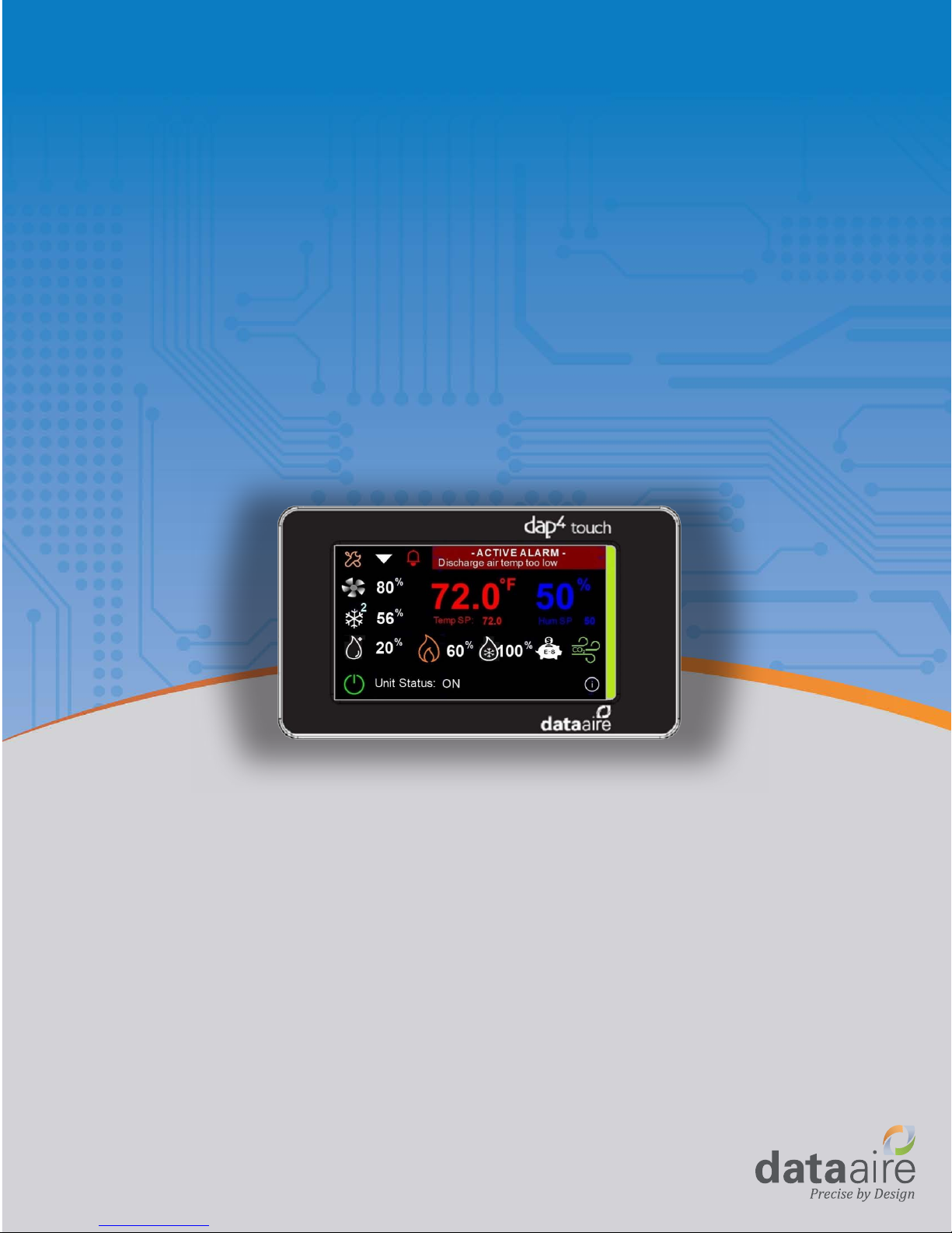
dap4 touch
User Manual
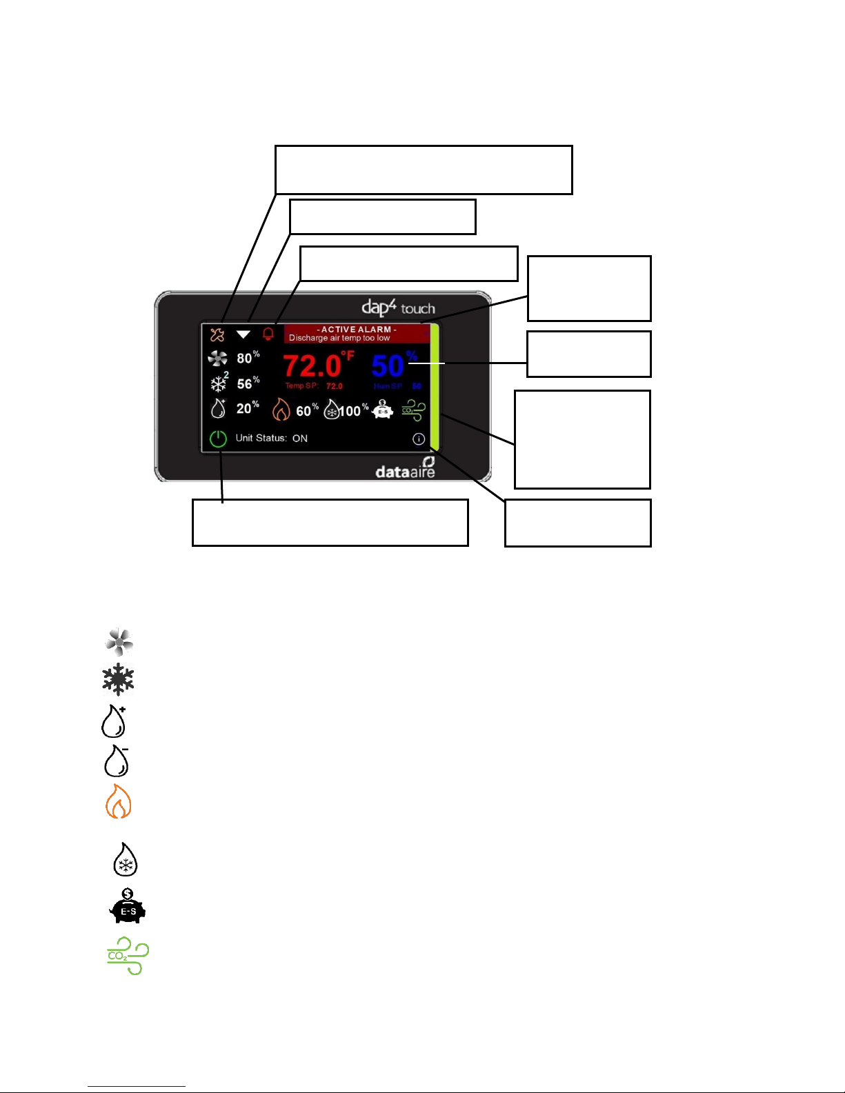
Displays the Set
Points screen.
Displays the system
Information Screen.
1. Home Screen
Go to monochrome display emulation mode
to access set-up menus.
Displays the next screen.
Displays the Alarm Log screen.
Turns the unit on or off.
Red = unit is off, Green = unit is on.
Pop-up Active
Alarm message
screen.
LED Unit Status
White = Fan On
Blue = Cooling
Green = E-Saver
Red = Alarm
There are several touch sensitive icons on the home screen. Listed below is how each one works when it is touched.
2. Home Screen Status Icons:
Icons will appear when a specific operation is running as described below:
Fan On – If fan is EC fan type, speed modulation percentage is also shown.
Compressor On - A number next to the icon appear indicates cooling stages. If compressor is
variable speed type, speed modulation percentage is also shown.
Humidifier On - If modulating type, humidity demand modulation is also shown.
Dehumidification On
Heaters On - A number next to the icon indicates how many stages are on. If SCR reheat type,
heat modulation percentage is also shown.
Chilled Water Cooling On – If unit has a modulating valve, valve modulation percentage is also
shown.
Energy Saver Available – Shown when optional energy saver chilled water is available to
provide cooling.
CO2 Valve On – (gPOD model that has CO2 control enabled only).
2
3. Navigating through screens
Note: If the touch display is too sensitive for the user’s finger, use a stylist such as pen or pencil.
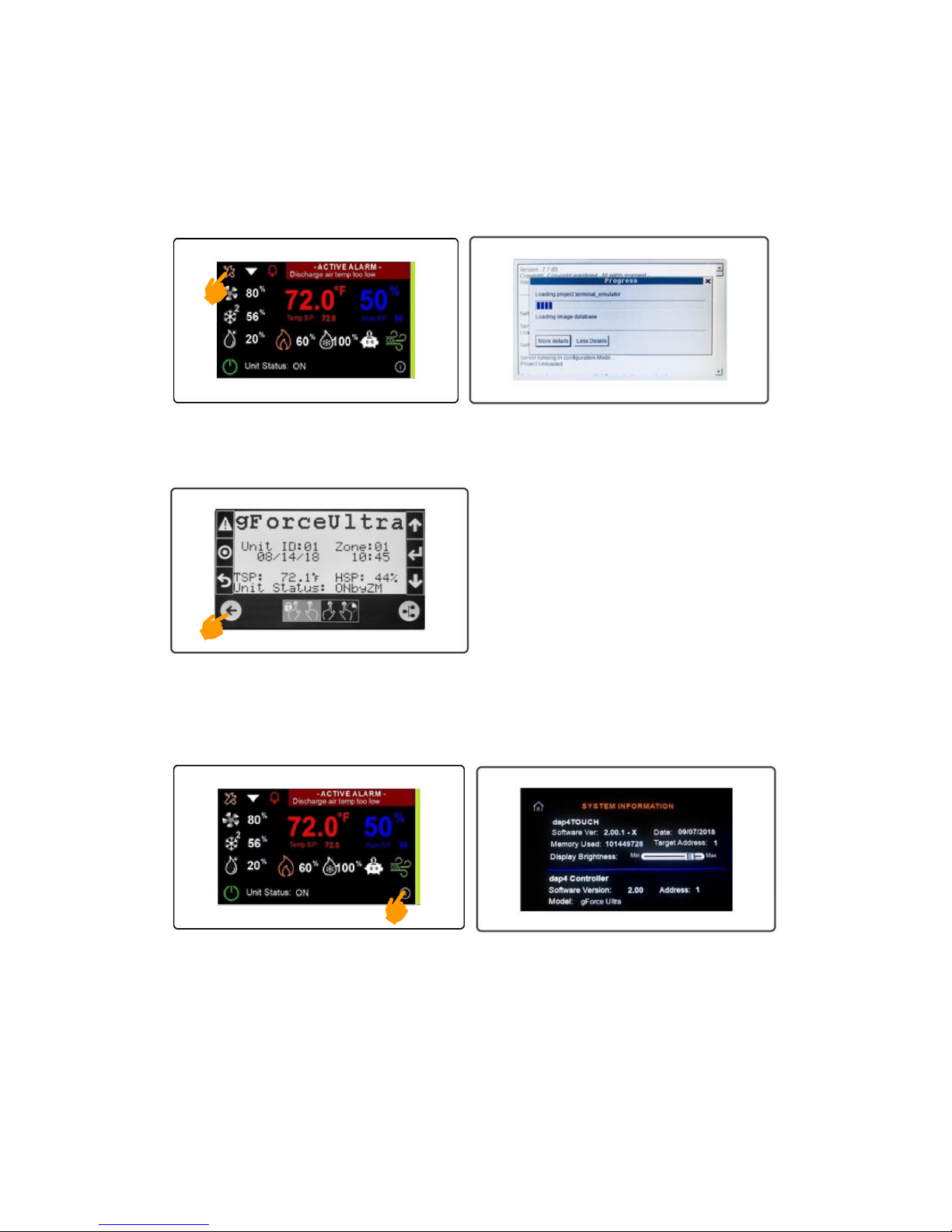
a) LCD Emulation and Programming Mode
Press and hold the Tool icon on the Home screen and wait for the monochrome LCD emulation mode to
load.
This mode is used to access menus to change settings such as alarm limits, deadbands, or unit configuration.
Please refer to the dap4 IOM for details on using this mode. Press arrow circle to exit the monochrome LCD
emulation mode and return to color graphic mode.
b) View System Information and setting the Target Address
On the home screen, press the lower right-side circle to display the System Information screen.
The dap4touch default Target Address is 1 because the dap4 controller’s default address is 1. Only when
the Zone Master option is enabled does the target address need to be changed. Press the Target
Address to show the keypad and enter a new Target address. There will be a short delay before the dap4
Address matches the new Target Address as illustrated below. NOTICE: These two addresses must
always be the same or there is a communications error with the targeted dap4 controller.
3

c) View Optional Status Screen
Press the down arrow to display the status of optional sensors (if any are installed).
On any status screen, pressing the Home icon returns to Home screen and pressing the down arrow icon
displays the next status screen.
d) View Rack Temperatures or Variable Speed Compressor Status
4

e) Optional Zone Master Status
If the unit is the master in a Zone Master network, the following screens will appear.
All units in the network indicate their status by color:
Green = Unit is On Blue = Unit is in Standby Red = Unit is in Alarm Gray = Unit is set to not to
participate in the zone master control.
Touch the unit’s icon to see specific information about that unit.
f) View Optional Power Meter and Airside Economizer Status
If unit equipped with an optional power meter or Airside economizer damper option, their status screens
will appear.
g) View Trending of Temperature and Humidity
These screens display trends of the return air temperature, humidity and optional discharge air
temperature and chilled water temperature. To display the legend information, touch the information icon
located at the top right corner. The Historical Trends screen can be scrolled forward or backwards by
pressing and dragging. Press the Clock icon to set the history time range, from 1 minute to 8 hours.
5

h) Silence Audible Alarm
Press Bell icon to silence the alarm buzzer and access the Alarm Log screen.
i) View Alarm History
Press the Up or Down icon to scroll thru past alarm logs. There will be a short delay as the next log is
loaded.
4. Changing Setpoints
On the Home screen, tap the temperature or humidity readings to access the setpoints screen. There are
two ways you can adjust the setpoints:
a) Using the Slider
Press and drag the slider to desired setpoint.
6
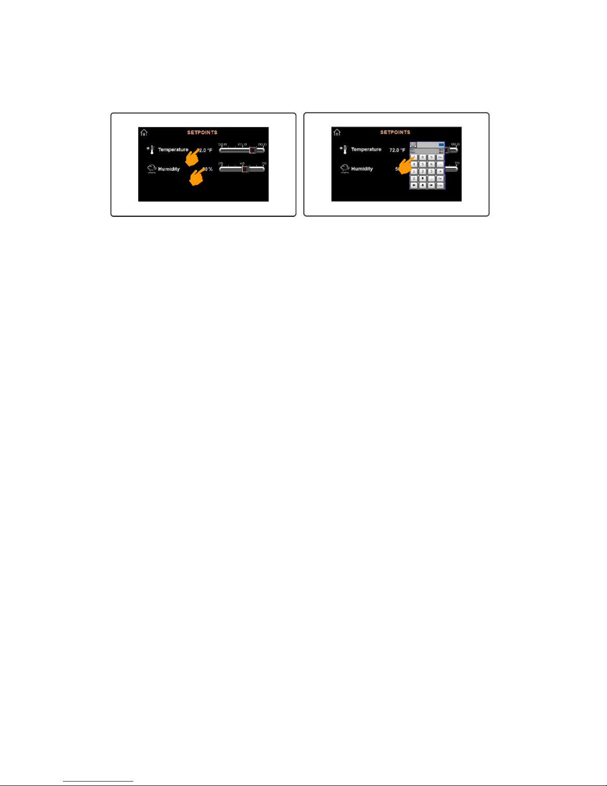
b) Using the Keypad
Tap on the setpoint and a keypad will appear. Enter the desired setpoint then press Enter to save the
setting and close the keypad.
7

dap4 touch
User Manual
Data Aire, Inc. | 230 W. BlueRidge Avenue | Orange, CA 92865 | www.dataaire.com
2018 Data Aire, Inc. | Precise by Design | ISO 9001 Certified | A member of Construction Specialties | Making Buildings Better
®
 Loading...