

Data Aire DAMA-01, DAMA-1.5, DAMA-2.5, DAMA-02, DAMW/G-01 Installation, Operation And Maintenance Manual
...
MINI CEILING UNITS
t
Installation, Operation and
Maintenance Manual
Packaged Unit
Packaged Uni
Split System


Table of Contents
1.0 Installation
1.1 Room Considerations ......................................................................................6
1.2 Inspection ........................................................................................................6
1.3 Locating the unit ..............................................................................................6
1.3.1 Vertical airfl ow units ..............................................................................7
1.3.2 Air cooled packaged units .....................................................................7
1.3.3 Horizontal airfl ow units..........................................................................8
1.3.4 Indoor condensers and condensing units .............................................8
1.4 Paper work ......................................................................................................8
1.5 Storage ............................................................................................................8
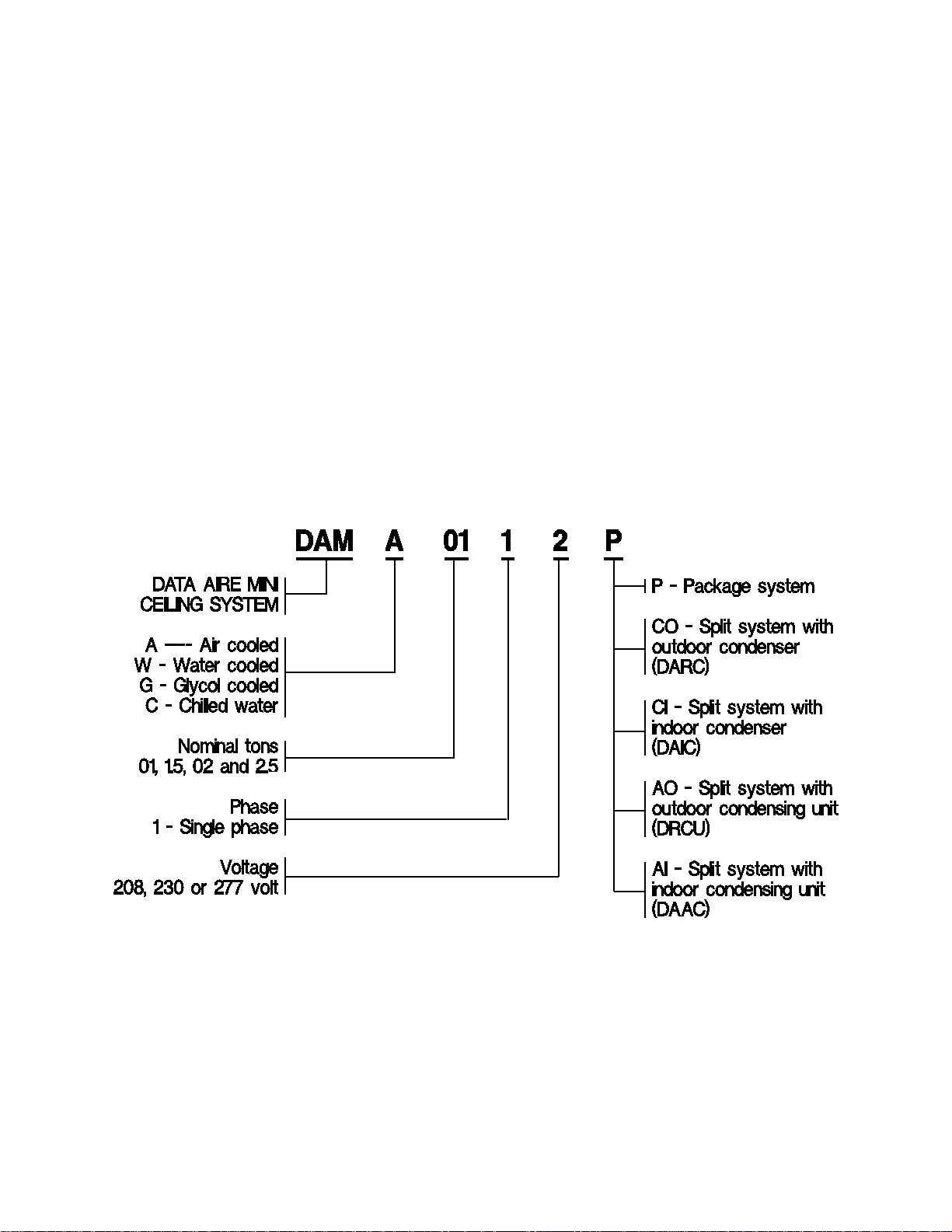
1.6 Model identifi cation ..........................................................................................9
2.0 Piping
2.1 Split air cooled unit piping ..............................................................................10
2.1.1 Discharge lines ...................................................................................10
2.1.2 Liquid lines ..........................................................................................10
2.1.3 Suction lines ........................................................................................ 11
2.1.4 Connection sizes, aif cooled units ...................................................... 11
2.1.5 Field piping - remote condenser .........................................................11
2.1.6 Field piping - remote condensing unit .................................................12
2.2 Water/glycol unit piping
2.2.1 Field piping - water/glycol system .......................................................12
2.2.2 Connection sizes - water/glycol system ..............................................13
2.2.3 Connection sizes - fl uid coolers (dry coolers) .....................................13
2.3 Auxiliary chilled water coil piping ...................................................................14
2.4 Condensate drain piing ..................................................................................14
2.5 Humidifi er piping ............................................................................................14
2.6 Leak testing ...................................................................................................14
2.7 Evacuation .....................................................................................................15
3.0 Electrical connections
3.1 Electrical service ............................................................................................16
3.2 Nameplate rating ...........................................................................................16
3.3 Grounding ......................................................................................................16
3.4 Voltage tolerance ...........................................................................................16
3.5 Auxiliary control wiring ...................................................................................16
3.6 Remote shutdown ..........................................................................................17
3.7 Remote alarm contacts ..................................................................................17
3.7.1 Mini DAP II units .................................................................................17
3.7.2 Mini DAP III units ................................................................................17
3.8 Remote sensors ............................................................................................17
3.8.1 Mini DAP II units .................................................................................17
3.8.2 Mini DAP III units ................................................................................18
3.9 Condensate pumps .......................................................................................18
3

4.0 Installation of remote outdoor heat exchanger
4.1 Rigging ..........................................................................................................19
4.2 Leg assembly ................................................................................................19
4.3 Locating the remote heat exchanger .............................................................19
4.4 Electrical Service ...........................................................................................20
4.5 Air cooled condensers - Model DARC ...........................................................20
4.5.1 Fan speed control ...............................................................................20
4.6 Fluid coolers - model DAFC ..........................................................................20
4.6.1 Fluid-sensing thermostats...................................................................20
4.6.2 Energy saver cooling ...........................................................................21
5.0 Charging
5.1 Voltage phase check .....................................................................................22
5.1.1 Evaporator ..........................................................................................22
5.1.2 Secondary heat exchanger .................................................................22
5.2 Air cooled systems ........................................................................................22
5.2.1 Package air cooled systems ...............................................................22
5.2.2 Split indoor air cooled systems charging - indoor condenser .............23
5.2.3 Fan speed control system charging - outdoor condenser ..................24
5.2.4 Flooded system charging....................................................................25
5.3 Water/glycol cooled systems .........................................................................26
5.3.1 Water/glycol cooled system charging .................................................26
5.3.2 Factor charge for water/glycol cooled systems...................................26
5.4 Refrigerant handling ......................................................................................27
5.5 Important refrigeration components ...............................................................27
5.5.1 Expansion valve..................................................................................27
5.5.2 High pressure cut out switch...............................................................27
5.5.3 Low pressure cut out switch ...............................................................27
6.0 Glycol Systems
6.1 Glycol concentrations ....................................................................................28
6.2 Internal (fl uid) volume ....................................................................................28
6.3 Fluid cooler internal volume ...........................................................................28
6.4 Copper piping internal volume .......................................................................28
6.5 Freezing point or aqueous solutions ..............................................................29
7.0 Controls
7.1 Standard thermostat ......................................................................................30
7.2 Optional programmable thermostat ...............................................................30
7.3 Optional Mini DAP II microprocessor control panel .......................................30
7.4 Optional Mini DAP III microprocessor control panel ......................................30
7.5 Optional DAP III .............................................................................................30
7.6 Wiring diagrams .............................................................................................31
8.0 Regular maintenance items ...................................................................................32
8.1 Air fi lters .........................................................................................................32
8.2 Belts ...........................................................................................................32
8.3 Bearings ........................................................................................................32
4

8.4 Humidifi er canisters .......................................................................................33
8.5 Fuses ...........................................................................................................33
8.6 Heating elements ...........................................................................................33
8.7 Refrigerant fi lter drier .....................................................................................33
9.0 Warranty policy ......................................................................................................34
10.0 Contact Data Aire ..................................................................................................35
11.0 Reference
Recommended line sizing for air cooled split systems ..................................36
Temperature-pressure chart ..........................................................................37
Superheat and Suction Pressure Trouble Shooting Guide ............................38
Maintenance/Inspection Check List ...................................................................
5
1.0 INSTALLATION
WARNING: There is no intent on the part of Data Aire, Inc. to defi ne local codes and
statutes which may supersede common trade practices. The manufacturer assumes
no responsibility for their interpretation. Consult local building codes and the National
Electrical Code for special installation requirements.
1.1 Room Considerations
Precision air conditioning equipment is designed to control spaces within close tolerances of temperature and humidity. However, the room must be built with a proper vapor barrier. A fi lm of poly-
ethylene is often used on walls and ceilings. Floors must be painted with vapor seal paint. All doors
to the controlled space should be equipped with weather seals to prevent the infi ltration of non-
neutral conditioned air from entering the space. Failure to provide a vapor barrier can compromise
the ability to control space conditions.
Introduction of outside air into the controlled space should be minimized. Outside air in excess of
5% of the total circulated air volume can have a signifi cant effect on the overall space conditions and
result in poor space control. All outside air that is introduced should be conditioned to the humidity
and temperature parameters of the computer room air conditioned (CRAC) unit setpoints to maintain the room’s design conditions.
1.2 Inspection
This equipment has been factory run-tested and has gone through a comprehensive inspection prior to its packaging and shipment to ensure that it arrives in excellent condition. However, shipping
damage can occur and a visual inspection of the outer crating immediately upon delivery should be
performed.
Note any external damage or other transportation damage on the freight carrier’s forms. Inspect the
unit itself for internal damage. A claim should be fi led with the shipping company if the equipment
is damaged or incomplete.
Loose items such as remote control panel, disconnect switch handle and spare belts are packed
inside the unit. Refer to the yellow shipping tag located on the electrical section panel.
WARNING: Freight damage claims are the responsibility of the purchaser. Action to
recover losses should be fi led immediately. Please notify Data Aire of any claims.
1.3 Locating the Unit
The unit is intended for above the ceiling installation and is typically suspended from structural
members in the building above the ceiling. Add a 50% safety factor to the weight of the unit to determine the strength of the supporting structural members.
Appropriate service access above the ceiling is required around all service and electrical access
panels. There must unobstructed clearance below the unit allowing ladder access to enable routine
maintenance and service.
6
NOTE: There are many available unit confi gur ations f or Mini Ceiling systems. Be sure to
identify the unit type and style before installing. There may be split condenser and condensing units that require separate or shared power.
NOTE: Condensation formation and frequent humidifi er fl ushing (units with humidifi -
er) are normal functions of this equipment. Drain connections must be made to ensure
proper water removal. Unit will require drain connections for condensate removal and
water connections for humidifi er make-up water, chilled water and/or hot water. Instal-
lation above equipment that could sustain water damage should be avoided.
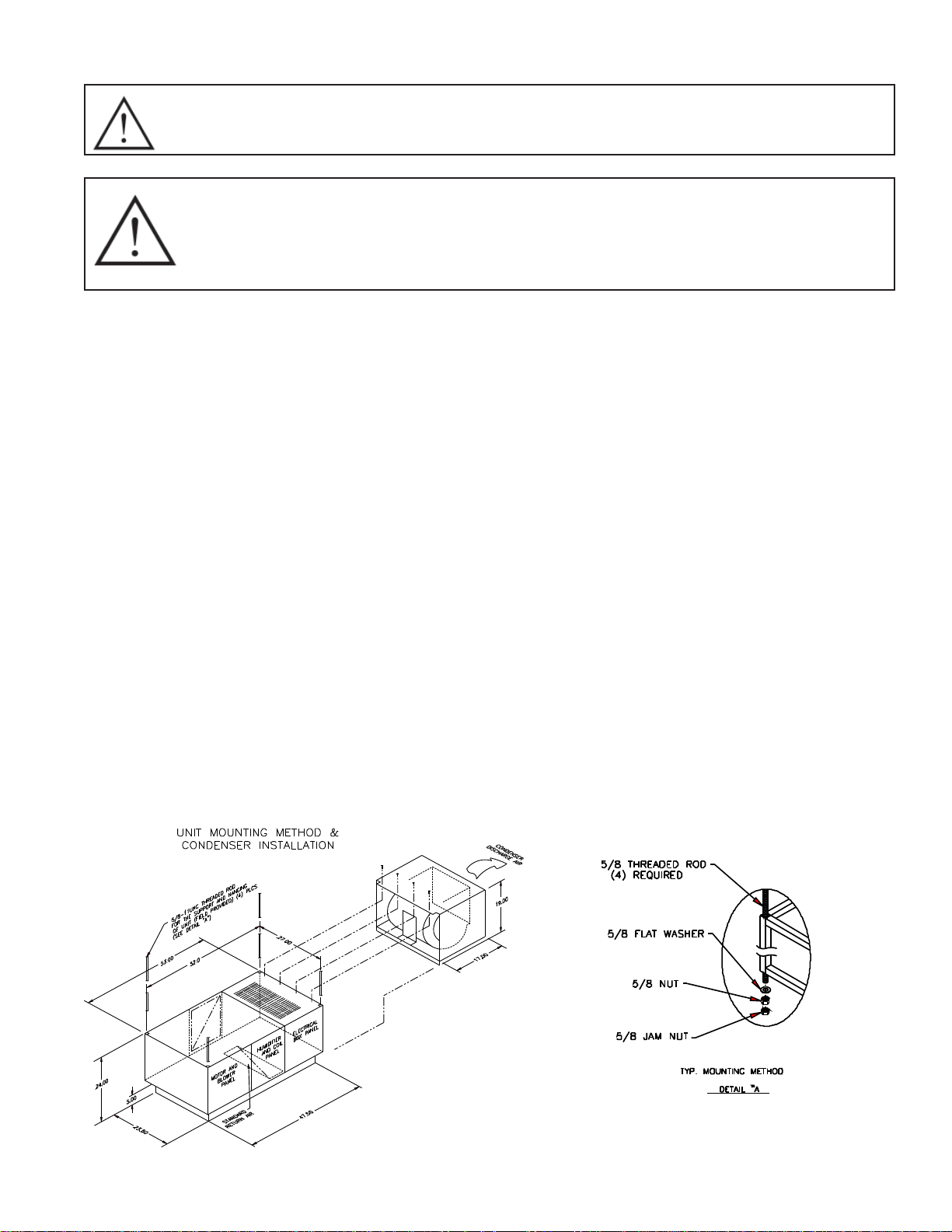
1.3.1 Vertical Airfl ow Units
The evaporator section is typically mounted over a standard 2’ x 4’ T-bar ceiling grid supported by
four threaded rods. The four threaded rods must be securely attached to the building structure.
Raise the evaporator section with an appropriate lifting device. Attach washers, nuts and nut jams
to each threaded rod. Tighten the nuts so the weight is supported evenly. Be sure the unit is level.
Allow for the depth (5”) of the supply/return air plenum when fi guring the height of the unit above
the ceiling.
The 5” tall vertical supply/return plenum assembly is attached to the bottom of the evaporator section once the evaporator section is installed. Six screws fasten the plenum to the evaporator section. The supply/return air grilles should be temporarily removed for access during installation. The
plenum typically mounts fl ush to the ceiling grid (depending on available space above unit).
1.3.2 Air Cooled Packaged Units
Air cooled package units require an additional condenser fan section to be mounted to the end of
evaporator section at the condenser coil. Place a gasket around the perimeter of the condenser
coil opening. Connect the female motor plug from the condenser blower section to the male plug
inside the evaporator section. Attach the condenser blower section using four (4) self-drilling # 10
sheet metal screws.
7
1.3.3 Horizontal Airfl ow Units
Ductwork is connected to factory provided duct collars on the supply and return air openings.
Four threaded support rods must be securely attached to the building structure. Raise the evapora-
tor section with an appropriate lifting device. Attach washers, nuts and jam nuts to each threaded
rod. Tighten the nut so the weight is supported evenly by the four rods and the unit is level.
NOTE: Some options call for a combination of vertical and horizontal airfl ow confi gurations.
In these cases a 5” plenum assembly as previously described is required.
1.3.4 Indoor Condensers and Condensing Units
Air cooled units are available with either an indoor condenser section or an indoor condensing unit
(units are also available with remote outdoor condenser or condensing units – outdoor sections
have their own installation, operation and maintenance manuals). Air cooled condensers and condensing units have factory provided duct collars on the supply and intake air openings (split water
cooling condensing units do not have airfl ow connections).
Four threaded support rods must be securely attached to the building structure. Raise the evaporator section with an appropriate lifting device. Attach washers, nuts and nut jams to each threaded
rod. Tighten the nut so the weight is supported evenly by the four rods and the unit is level.
Typical installations have the indoor condenser or indoor condensing unit near or adjacent to the
evaporator section especially when shared electrical power is required. The same service and
maintenance requirements apply to these units as well.
1.4 Paperwork
Each Data Aire unit ships with start-up sheets that must completed. The start-up sheets are enclosed in packet with the unit. The packet includes the warranty certifi cate, wiring diagrams, specifi c
component literature, warranty registration card and a copy of the unit’s Installation/Operation and
Maintenance manual.
A manila tag is attached to the outside panel to indicate articles that have been packaged and
shipped loose within the unit cabinet.
NOTE: It is the responsibility of the start-up service company to return the start -up sheets
and warranty registration card to Data Aire for activation of the unit warranty. Failure to
do so may cause delays in warranty related services and in some cases v oid the w arranty.
1.5 Storage
Your Data Aire equipment comes ready for immediate installation. In some instances it may be
necessary to store the equipment for a period of time. If you must store the equipment it should
be done in a dry area, out of the weather, protected from damage by other equipment in storage or
transportation equipment, never stacked and avoid frequent relocation.
8
If equipment is stored for longer than 30 days special precautions must be taken to avoid coil damage. All coils should be charged and sealed with a low pressure (less the 25 PSIG) inert gas, such
nitrogen. This prevents contaminants from entering the coils. When the seal is broken at installation, the rush of escaping gas verifi es the coil is still leak free. If coils are not charged and sealed,
condensation mixes with air pollutants forming a weak acid and over time can cause pinhole leaks
to develop in coil tubes.
When equipment is installed after storage, caution should be taken to inspect and replace, if required, rubber hoses and belts. All moving parts, such as blowers and motors, should be hand
tested to ensure they are free and clear prior to start-up. Finally, verify that all lubrication is fresh
and full.
1.6 Model Identifi cation
9

2.0 PIPING
2.1 Split Air Cooled Unit Piping
Refer to the attached line sizing chart on page
mate responsibility for line sizing selection is that of the installing contractor or the project engineer.
Data Aire does not assume this responsibility. The chart covers distances up to 200 equivalent feet.
For installations greater than this distance, consult ASHRAE or similar references.
Standard piping practices must be used to ensure proper oil return and effi cient operation. The
interconnecting lines to the remote air cooled condenser or condensing unit must be installed by
a qualifi ed refrigeration mechanic.
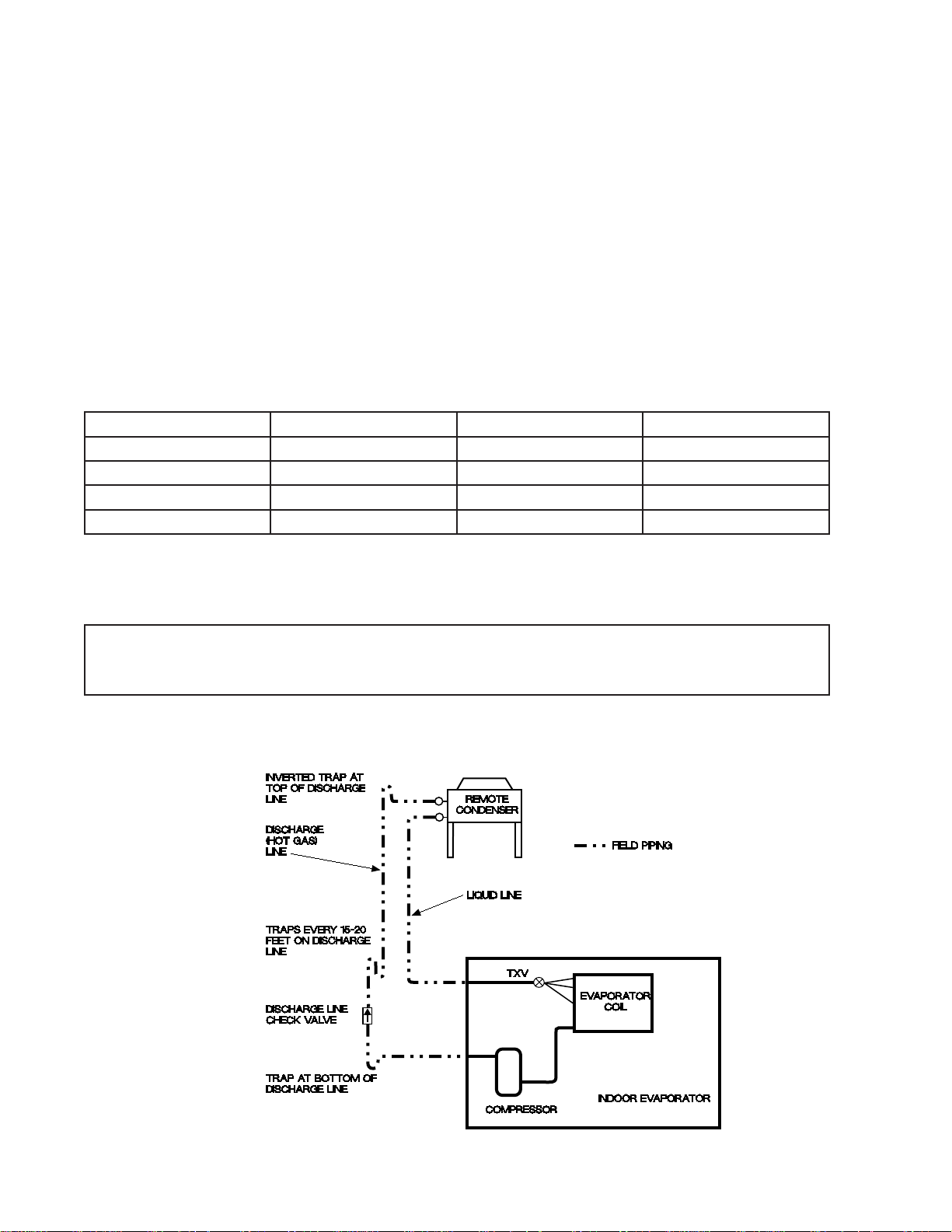
2.1.1 Discharge Lines
Discharge lines, also called hot gas lines, should be trapped at the top (inverted) and bottom, as
well as every 15 to 20 feet of vertical rise. Discharge line check valves are recommended on all
installations, especially those where there are long pipe runs or cold climate. Check valves should
be installed no less than 6 feet from the compressor. The discharge, suction and liquid lines need
to be refrigerant grade copper and in accordance with local code. All refrigeration piping should be
installed with high temperature brazed joints. When brazing, a supply of nitrogen gas needs to be
fed through the refrigerant lines. Be sure to open the other end of the refrigerant line to allow the
nitrogen to bleed off and not pressurize the piping. Prevailing good refrigeration practices should
be employed for piping support, leak testing, dehydration and charging of the refrigerant circuits.
During the installation the lines should be capped off and fi lled with dry nitrogen at the end of each
day’s work or until the system is completed and sealed.
36 for a guideline for sizing refrigerant lines. The ulti-
Data Aire recommends a silver/phosphorus/copper alloy with 5 to 15% silver to be used to braze
the refrigerant line sets to the indoor and outdoor units. Nitrogen needs to be fl owing through the
lines to eliminate carbon deposit build-up of the joints. Carbon could contaminate the refrigerant
and restrict the metering device.
Piping must be supported within 18” of the inlet and outlet connections. The inlet connection is
located on the top header of all units. The discharge outlet is located at the bottom of the header.
The discharge line pressure drop should not exceed 6 PSIG for R-407C and 9 PSIG for R-410A.
Recommended gas velocity for proper oil return is 1,000 FPM. Slope horizontal lines downward in
the direction of refrigerant fl ow, 1/2” for every 10 feet of line length. Discharge lines do not require
insulation but due to the high temperatures of the refrigerant inside the line, the pipes may be insulated to protect against burns to individuals near or around the lines.
2.1.2 Liquid Lines
Liquid lines are determined by pressure drop and velocity . The liquid line pressure drop for R-407C
should not exceed 5 PSIG. For systems with R-410A, the pressure drop should not exceed 9
PSIG. The recommended velocity should be between 200 and 300 FPM. To avoid excessive liquid
line pressure drop, the air cooled condenser should be located above or at the same level as the
10
evaporator. Condenser installations more than 10 feet below the evaporator are not recommended.
Insulation of liquid lines is not required but can be useful in preventing condensation from forming
and to avoid fl ashing on long pipe runs.
2.1.3 Suction Lines
Some applications call for the compressor to be mounted as part of the condenser, more commonly
referred to as a condensing unit. Such require fi eld piping of liquid and suction lines. Suction lines
are trapped similarly to discharge lines. Common practice for suction line selection and installation
should be followed. Suction lines should always be insulated.
2.1.4 Connection Sizes, Air Cooled Units
MODEL HOT GAS LINE LIQUID LINE SUCTION LINE
DAMA-01 1/2” 1/2” 3/4”
DAMA-1.5 1/2” 1/2” 3/4”
DAMA-02 1/2” 1/2” 3/4”
DAMA-2.5 1/2” 1/2” 3/4”
Note: Units will have a liquid line and either a hot gas or suction line
Field connections at the indoor evaporator and remote condenser or condensing unit will
not necessarily be the same as the fi eld pipe size required. In some cases these sizes will
vary signifi cantly .
2.1.5 Field Piping, Remote Condenser
11

2.1.6 Field Piping, Remote Condensing Unit
2.2 Water/Glycol Unit Piping
The required fi eld installed condenser water pipe sizes may or may not be the same as the connec-
tion sizes at the evaporator section or fl uid cooler (refer to Sections 2.2.2 and 2.2.3 for connection
sizes). Water pipe sizes will depend on the length of pipe required and the calculated pressure drop
of peripheral components.
Water cooled units may also be connected to building water or tower water sources. Pipe size will
depend on length of run and the maximum water fl ow required.
All water/glycol units are shipped with plate/fi n heat exchangers as standard equipment. A strainer
is shipped loose and is to be fi eld installed in the supply line with shut-off valves (fi eld provided)
before and after the strainer. The strainers and water/glycol piping must be cleaned on a periodic
basis. If the unit is shipped with optional shell and tube condenser, strainers are not required nor
shipped with the unit.
All water pipes have a cap installed on the end of the pipe for pressure testing the system. These
caps need to be removed before installing the water piping to the unit. Use a tube cutter for smaller
pipes and a reciprocating saw with a metal cutting blade for larger pipe sizes or if there is a clearance problem. All connections need to be cleaned before connections are brazed together.
NOTE: One of the most common problems in a water/glycol system is the presence of air
in the condenser loop. Air vents must be installed in various locations in the piping system
to purge the air.
Water/glycol system piping may include a centrifugal pump (or pumps for redundancy). Pumps
must be primed before operating per the pump manufacturer’s guidelines.
12
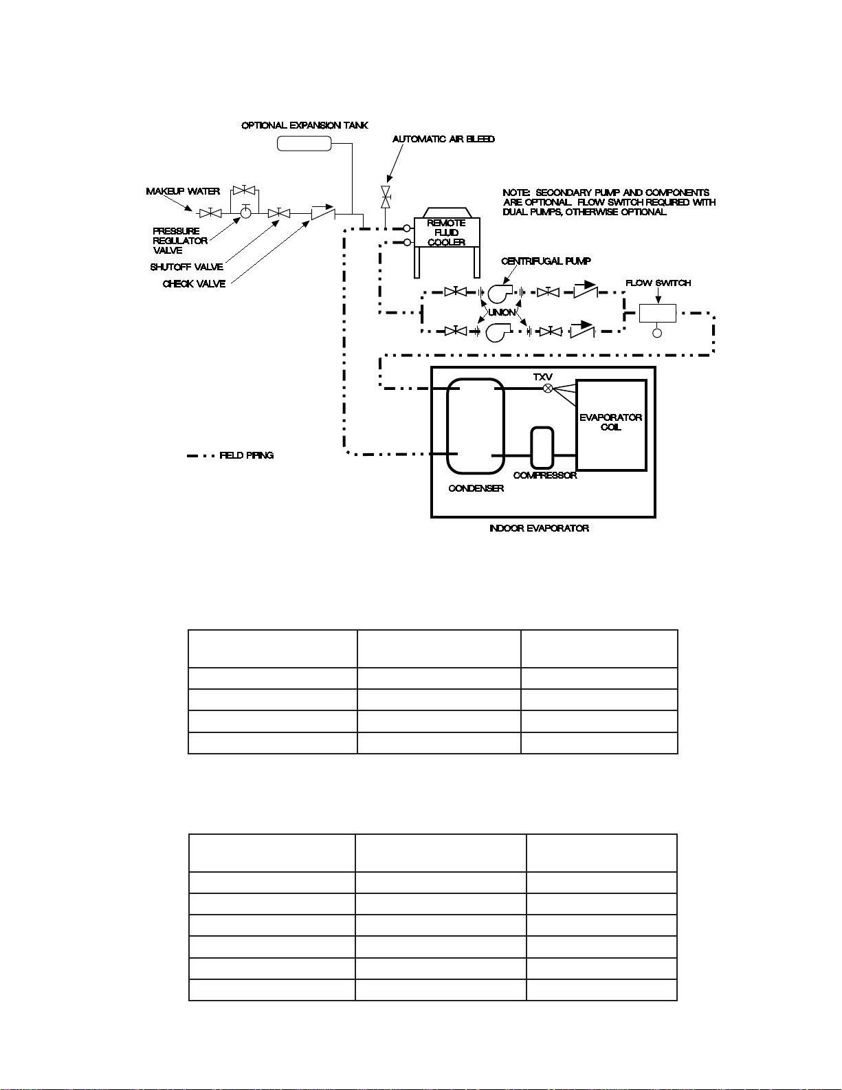
2.2.2 Field Piping, Water/Glycol System
2.2.3 Connection Sizes, Water/Glycol Cooled Units
EVAPORATOR
MODEL
DAMW/G-01 3/4” O.D. 3/4” O.D.
DAMW/G-1.5 3/4” O.D. 3/4” O.D.
DAMW/G-02 3/4” O.D. 3/4” O.D.
DAMW/G-2.5 3/4” O.D. 3/4” O.D.
WATER IN
CONNECTION
2.2.3 Connection Sizes, Fluid Coolers (Dry Coolers)
EVAPORATOR
MODEL
DAFC-06 1-5/8” O.D. 1-5/8” O.D.
DAFC-07 1-5/8” O.D. 1-5/8” O.D.
DAFC-09 1-5/8” O.D. 1-5/8” O.D.
DAFC-11 2-1/8” O.D. 2-1/8” O.D.
DAFC-15 2-1/8” O.D. 2-1/8” O.D.
DAFC-17 2-5/8” O.D. 2-5/8” O.D.
WATER IN
CONNECTION
WATER OUT
CONNECTION
WATER OUT
CONNECTION
13

2.3 Auxiliary Chilled Water Coil Piping
Units with an optional Auxiliary Chilled Water cooling coil require a separate source of chilled water.
The chilled water connection sizes will be the same as those listed for the condenser water (see
chart in Section 2.2.3). Units with optional Energy Saver coil typically have shared or common piping with the condenser supply and therefore do not require a separate cooling source.
All water pipes have a cap installed on the end of the pipe for pressure testing the system. These
caps need to be removed before installing the water piping to the unit. Use a tube cutter for smaller
pipes and a reciprocating saw with a metal cutting blade for larger pipe sizes or if there is a clearance problem. All connections need to be cleaned before connections are brazed together.
2.4 Condensate Drain Piping
The evaporator section is provided with a 3/4” FPT connection on the bottom for condensate removal. Units with vertical air discharge have the 5” plenum below the evaporator drain pan with
knockouts that allow fi eld supplied ad installed condensate lines to be routed out either side. A
union is recommended at the fi eld connection which will permit easy disconnection from the unit for
cleaning.
A trap should be built into the drain line to prevent air from backing up into the unit. Drain lines
should be pitched downward not less than 1/4” for each 10 feet of horizontal run. Do not reduce the
size of the drain line. Where local codes permit, PVC pipe may be used.
Some applications or installations have no convenient means of allowing a gravity drain. In this
case a condensate pump can be used. An optional condensate pump can be factory mounted and
wired or shipped loose for fi eld installation. Factory mounted pumps do not require a separate
power source.
Optional condensate that are shipped loose (or fi eld provided) typically require a dedicated 1 10 volt
power source. Field pipe connections must be made to the pump discharge connection. A check
valve must be installed to prevent short cycling.
2.5 Humidifi er Piping
The optional humidifi er on Mini Ceiling systems is a steam generator type with disposable cylinder.
The humidifi er make-up water should be brought to the humidifi er through the fi eld connection open-
ing using 1/4” copper tubing. A compression fi tting is provided at the humidifi er. A shut-off valve
should be provided outside the unit to allow disconnection of service. An in-line water pressure
regulator and strainer should be installed. Water pressure should be set between 30 and 80 PSI.
The humidifi er has a drain at the bottom which is factory piped to the main condensate drain line.
The dispersion tube also has a drain line. No additional fi eld piping is required.
2.6 Leak Testing
No installation is complete until the entire system has been thoroughly checked for leaks. This includes checking refrigerant tubing, fl are fi ttings, pressure controls, shraeder fi ttings and compressor
rotolock service valves. Check both fi eld and factory connections.
14
 Loading...