

Data Aire DALA 06, DALA 13, DALA 08, DALA 10, DALW 06 Installation, Operation And Maintenance Manual
...
LCS
Installation, Operation and Maintenance Manual
6, 8, 10 and 13 ton
Air, Water and Glycol Cooled DX and Chilled Water
Congratulations!
You have selected a Data Aire precision control system, one of the fi nest available in
the market today. Proper installation, operation and maintenance of this equipment
will ensure years of optimal performance.
This manual is intended to assist trained service personnel by providing
necessary guidelines for this particular equipment. Service to Data Aire units
should be done by qualifi ed individuals with an adequate background in areas
such as HVAC, electrical, plumbing and electronics, as applicable.
Service performed by unauthorized or unqualified technicians may void
manufacturers’ warranties and could result in property damage and/or personal
injury.
Special care should be given to those areas where these symbols appear.
Data Aire, Inc. reserves the right to make design changes for the purposes of
product improvement, or to withdraw any design without notice.
Table of Contents
1.0 INSTALLATION ........................................................................................................6
1.1 Room Considerations ....................................................................................................6
1.2 Inspection .......................................................................................................................6
1.3 Locating the Unit .............................................................................................................6
1.3.1 Horizontal Airfl ow Units .............................................................................................7
1.3.2 Vertical Airfl ow Units ..................................................................................................7
1.4 Paperwork.......................................................................................................................7
1.5 Storage ...........................................................................................................................8
1.6 Model Identifi cation .........................................................................................................8
2.0 PIPING ........................................................................................................................9
2.1 Split Air Cooled Unit Piping .............................................................................................9
2.1.1 Discharge Lines.........................................................................................................9
2.1.2 Liquid Lines ...............................................................................................................9
2.1.3 Suction Lines .............................................................................................................9
2.1.4 Connection Sizes, Air Cooled Units.........................................................................10
2.1.5 Field Piping, Remote Condenser ............................................................................11
2.1.6 Field Piping, Remote Condensing Unit ...................................................................11
2.2 Water/Glycol Cooled Unit Piping ..................................................................................12
2.3 Auxiliary Chilled Water Coil Piping ...............................................................................13
2.4 Condensate Drain Piping ..............................................................................................13
2.5 Humidifi er Piping...........................................................................................................13
2.6 Dry Steam Humidifi er ....................................................................................................13
2.7 Leak Testing ..................................................................................................................14
2.8 Evacuation ....................................................................................................................14
3.0 ELECTRICAL CONNECTIONS ..........................................................................15
3.1 Electrical Service ..........................................................................................................15
3.2 Nameplate Ratings .......................................................................................................15
3.3 Grounding .....................................................................................................................15
3.4 Voltage Tolerance .........................................................................................................15
3.5 Auxiliary Control Wiring ................................................................................................15
3.6 Remote Shutdown ........................................................................................................16
3.7 Remote Alarm Contacts ................................................................................................16
3.8 Remote Sensors ...........................................................................................................16
3.9 Condensate Pumps ......................................................................................................16
4.0 INSTALLATION OF REMOTE OUTDOOR HEAT EXCHANGER .............17
4.1 Rigging..........................................................................................................................17
4.2 Leg Assembly ...............................................................................................................17
4.3 Locating the Remote Heat Exchanger ..........................................................................17
4.4 Electrical Service ..........................................................................................................18
3

Table of Contents, continued
4.0 INSTALLATION OF REMOTE OUTDOOR HEAT EXCHANGER - (continued)
4.5 Air Cooled Condensers - Model DARC .............................................................................18
4.5.1 Fan Speed Control .......................................................................................................18
4.5.2 Ambient Thermostats ...................................................................................................18
4.6 Fluid Coolers - Model DAFC ..............................................................................................19
4.6.1 Fluid-Sensing Thermostats ..........................................................................................19
4.6.2 Energy Saver Cooling ..................................................................................................19
5.0 CHARGING ...................................................................................................................20
5.1 Voltage Phase Check ..........................................................................................................20
5.1.1 Evaporator ....................................................................................................................20
5.1.2 Secondary Heat Exchanger .........................................................................................20
5.2 Air Cooled Systems ......................................................................................................20
5.2.1 Split Indoor Air Cooled Systems Charging ...................................................................20
5.2.2 Fan Speed Control System Charging...........................................................................21
5.2.3 Flooded System Charging ............................................................................................21
5.3 Water/Glycol Cooled Systems ......................................................................................22
5.3.1 Water/Glycol Cooled Systems Charging ......................................................................22
5.4 Refrigerant Handling .................................................................................................... 23
5.5 Important Refrigeration Components ...........................................................................23
5.5.1 Expansion Valve ...........................................................................................................23
5.5.2 High Pressure Cutout Switch ......................................................................................24
5.5.3 Low Pressure Cutout Switch ........................................................................................24
6.0 GLYCOL SYSTEMS ...................................................................................................24
6.1 Glycol Concentration .........................................................................................................24
6.2 Internal (Fluid) Volume.......................................................................................................24
6.3 Fluid Cooler Internal Volume .............................................................................................24
6.4 Copper Piping Internal Volume ..........................................................................................25
6.5 Freezing Point of Aqueous Solutions .................................................................................25
7.0 CONTROLS ..................................................................................................................25
7.1 Mini dap4 Controller...........................................................................................................25
7.2 Optional Expanded dap4 Controller...................................................................................25
7.3 Secondary Heat Exchangers .............................................................................................25
7.4 Wiring Diagrams ................................................................................................................26
4

Table of Contents, continued
8.0 REGULAR MAINTENANCE ITEMS (continued)
8.4 Humidifi er Canisters .........................................................................................................27
8.5 Fuses ................................................................................................................................28
8.6 Heating Elements .............................................................................................................28
8.7 Refrigerant Filter Drier ......................................................................................................28
9.0 WARRANTY ................................................................................................................29
10.0 CONTACT DATA AIRE ...........................................................................................30
Line Sizing Chart .......................................................................................................................31
Monthly Maintenance Inspection Checklist ...............................................................................32
Quarterly Maintenance Inspection Checklist .............................................................................33
Superheat and Suction Pressure Troubleshooting Guide .........................................................34
Temperature Pressure Chart for R-407c and R-410a .................................................................35
INDEX ...............................................................................................................................36-37
5
1.0 INSTALLATION
There is no intent on the part of Data Aire, Inc. to defi ne local codes or statutes which
may supersede common trade practices. The manufacturer assumes no responsibility
for their interpretation. Consult local building codes and the National Electrical Code
for special installation requirements.
1.1 Room Considerations
Precision air conditioning equipment is designed to control spaces within close tolerances of
temperature and humidity. However, the room must be built with a proper vapor barrier. A fi lm of
polyethylene is often used on walls and ceilings. Walls and fl oors must also be painted with a vapor-
seal paint. All doors to the controlled space should be equipped with weather seals to prevent the
infi ltration of non-neutral conditioned air from external spaces. Failure to provide a vapor barrier can
compromise the ability to control space conditions.
Introduction of outside air into the space should be minimized. Outside air in excess of 5% of the
total circulated air volume can have a signifi cant effect on the overall space conditions and result
in poor space control. All outside air that is introduced should be conditioned to the humidity and
temperature parameters of the computer room air conditioner (CRAC) unit set points to maintain
proper room conditions and to prevent the CRAC units from running excessively to maintain the
room’s conditions.
1.2 Inspection
This Data Aire unit has been factory run-tested and has gone through a comprehensive inspection
prior to its packaging and shipment to ensure that it arrives in excellent condition. However, shipping
damage can occur and a visual inspection of the outer crating immediately upon delivery should be
performed.
Note any external damage or other transportation damage on the freight carrier’s forms. Inspect the
unit itself for internal damage. A claim should be fi led with the shipping company if the equipment
is damaged or incomplete.
Loose items such as remote control panels, disconnect switch handles, spare belts and spare fi lters
are packed inside the unit. Refer to the manila shipping tag located on the unit panel for details.
Freight damage claims are the responsibility of the purchaser. Action to recover
losses should be fi led immediately. Please notify factory personnel of any claims.
1.3 Locating the Unit
The unit is intended for above the ceiling installation and is typically suspended from structural
members in the building above the ceiling. Add at least a 50% safety factor to the weight of the unit
to determine the necessary strength of the supporting structural members or follow local code.
Appropriate service access above the ceiling is required around all service and electrical access
panels. There must be unobstructed clearance below the unit allowing ladder access to enable
routine maintenance and service. Consult local building codes and National Electric Code for special
installation requirements.
6
Note: There are many available unit confi gurations for the LCS. Be sure to identify the
unit type and style before installing. For instance there may be split condenser/condensing
sections requiring separate or shared power.
Note to Installing Contractor: Condensation formation and frequent humidifi er fl ush-
ing (when humidifi er is installed) are normal functions of this equipment. Drain connec-
tions must be made to ensure proper water removal. Unit will require drain connections
for condensate removal and water connections possibly for humidifi er (when installed)
makeup water, condenser water , chilled water and/or hot water . Installation of units above
equipment that could sustain water damage should be avoided.
1.3.1 Horizontal Airfl ow Units
All LCS units have horizontal airfl ow confi guration with a 29.5” tall evaporator section. Duct collars
are factory provided for the supply and return air.
Four threaded support rods must be securely attached to the building structure. Two fi eld provided
support channels connect to the pairs of threaded support rod. (See detail on drawing 536-900-100
shown on page 38.) Raise the evaporator section with an appropriate lifting device. Attach washers,
nuts and jam nuts to each threaded rod. Tighten the nuts so the weight is supported evenly by the
four rods and the unit is level.
1.3.2 Indoor Condensers and Condensing Units
Although most split air cooled systems have outdoor condensers or condensing units, indoor
condensers and condensing units are occasionally used. These 29.5” tall sections are to be mounted
in the same manner as the evaporator sections using four threaded rods. Air cooled condensers
or condensing units have factory provided duct collars on the supply and intake air openings as
appropriate.
Typical installations have the condenser or condensing section physically near the evaporator,
especially since most have some shared electrical line power. The mounting of these sections is
independent of the evaporator mounting. The same service and maintenance clearance requirements
apply to these units as well.
1.4 Paperwork
Each Data Aire unit ships with a start-up sheet that must be completed during installation. Also
included in the paperwork is a warranty/information packet that provides important wiring diagrams,
specifi c component literature, warranty registration card and other valuable paperwork, including a
copy of this Installation/Operation and Maintenance manual.
A manila (yellow) tag is attached to the outside panel to indicate articles that may have been packaged
and shipped loose within the unit cabinet. Typically this would be a condensate pump and other
loose components that are not factory mounted.
It is the responsibility of the installing contractor to return the start-up sheet and warranty
registration card to Data Aire for proper activation of the unit warranty. Failure to do so
may cause delays in warranty related services and in some cases void the warranty.
7
1.5 Storage
Your Data Aire equipment comes ready for immediate installation. In some instances it may be
necessary to store the equipment for a period of time. If you must store the equipment it should be
done in a dry area, out of the weather, in non-freezing temperatures, protected from damage by other
equipment in storage or transportation equipment, never stacked, and avoid frequent relocation.
CAUTION: Complete system drain-down cannot be assured for this product. Freezing
system fl uid can rupture piping.
If equipment is stored for longer than 30 days special precautions must be taken to avoid coil damage.
All coils should be charged and sealed with a low pressure (1-3 PSIG) inert gas, such as nitrogen.
This prevents contaminates from entering the coils; then when the seal is broken at installation, the
rush of escaping gas verifi es the coil is still leak free. If coils are not charged and sealed condensation
mixes with air pollutants forming a weak acid and over time can cause pin hole leaks to develop in
the coil tubes.
When equipment is installed after storage caution should be taken to inspect and replace, if required,
rubber hoses and belts. All moving parts, such as blowers and motors, should be hand tested to ensure
that they are free and clear prior to start-up. Finally, verify that all lubrication is fresh and full.
It is the responsibility of the installing contractor to return the start-up sheet and warranty registration
card to Data Aire for proper activation of the unit warranty. Failure to do so may cause delays and
in some cases void the warranty.
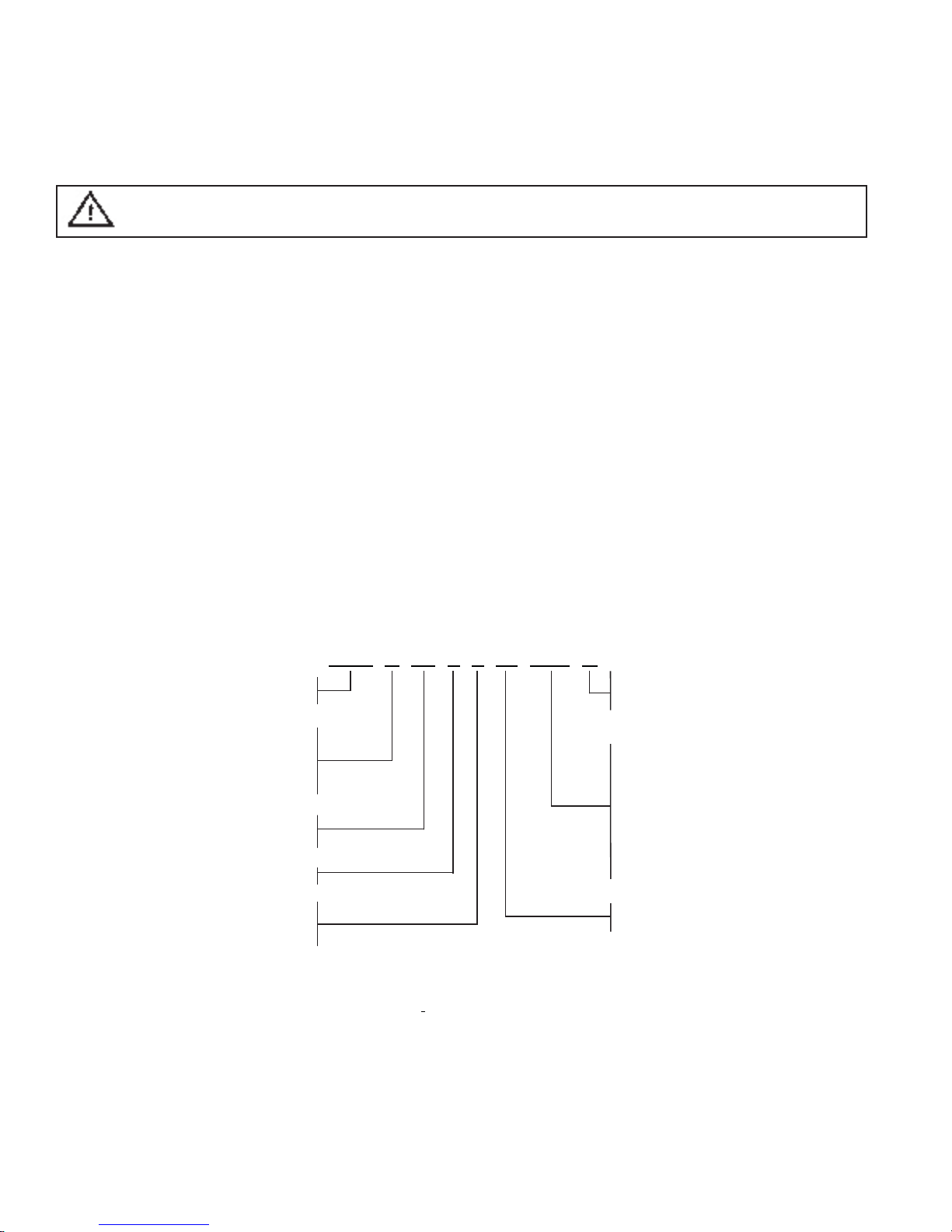
1.6 Model Identifi cation
LCS UNITS
DAL A 06 3 2 -E -CO D
DATA AIRE LCS D – Dual compressor
UNIT S – Single compressor
A ---------Air cooled
W ---- Water cooled P – Package system
G ----Glycol cooled
C ----Chilled water CO – Split system with
outdoor condenser (DARC)
Nominal tons
06, 08, 10 and 13 AO – Split system with
outdoor condensing unit
3 – Three phase (DRCU)
2 – 208 or 230 volt C – Auxiliary chilled water coil
4 – 460 volt E – Energy Saver
5 – 575 volt
LCS units are not available in air cooled packaged confi guration.
CONDENSER – Condenser coil only, no compressor
CONDENSING UNIT – Condenser coil and compressor
The order write-up should have the condenser or condensing unit model number.
Refer to applicable condenser or condensing model number identifi cation.
Example: DATA AIRE LCS unit, air cooled, 6 ton, 3Ø – 230 volt, split system
with outdoor condenser and dual compressors –
Evaporator model: DALA 0632 CO D Condenser model: DARC 0632
8
2.0 PIPING
2.1 Split Air Cooled Unit Piping
Refer to the attached line sizing chart on page 31 for a guideline for sizing refrigerant lines. The
ultimate responsibility for line size selection is that of the installing contractor or project engineer.
Data Aire does not assume this responsibility. The chart covers distances up to 200 equivalent feet.
For installations greater than this distance, consult ASHRAE or similar references.
Standard piping practice must be used to ensure proper oil return and effi cient operation.
The interconnecting lines to the remote air cooled condenser or condensing unit must
be installed by a qualifi ed refrigeration mechanic.
2.1.1 Discharge Lines
Discharge lines, also called hot gas lines, should be trapped at the top (inverted) and bottom, as well
as every 20 feet of vertical rise. Discharge line check valves are recommended on all installations,
especially those where there are long pipe runs or cold climate. Check valves should be installed no
less than six feet from the compressor. The discharge, suction and liquid lines need to be refrigerant
grade copper and in accordance with local code. All refrigeration piping should be installed with
high temperature brazed joints. When brazing, a supply of nitrogen gas needs to be fed through the
refrigerant lines. Be sure to open the other end of the refrigerant line to allow the nitrogen to bleed
off and not pressurize the piping. Prevailing good refrigeration practices should be employed for
piping support, leak testing, dehydration and charging of the refrigerant circuits. During the installation
the lines should be capped off and fi lled with dry nitrogen at the end of each day’s work or until the
system is completed and sealed.
Data Aire recommends a silver/phosphorus/copper alloy with 5 to 15% silver be used to braze the
refrigerant line sets to the indoor and outdoor units. Nitrogen needs to be fl owing through the lines to
eliminate carbon deposit buildup on the inside of the joints. Carbon could contaminate the refrigerant
and restrict the metering device.
Piping must be supported within 18” of the inlet and outlet connections. The inlet connection is located
on the top header of all units. The discharge outlet is located at the bottom of the header.
Discharge line pressure drop should not exceed 6 PSI for R-407c and 9 PSI for R-410a. Recommended
gas velocity for proper oil return is 1,000 FPM. Slope horizontal lines downward in the direction of
refrigerant fl ow, 1/2” for every ten feet of line length. Discharge lines do not require insulation but
due to the high temperatures of the refrigerant inside the line, the pipes may be insulated to protect
against burns to individuals near or around the lines.
2.1.2 Liquid Lines
Liquid line size is determined by pressure drop and velocity . The liquid line pressure drop for R-407c
should not exceed 5 PSI or 9 PSI for R-410a. The recommended velocity should be between 200
and 300 FPM. To avoid excessive liquid line pressure drop, the air cooled condenser should be
located above or at the same level as the evaporator. Condenser installation more than ten feet
below the evaporator is not recommended. Insulation of liquid lines is not required but can be useful
in preventing condensation from forming and to avoid fl ashing on long pipe runs.
2.1.3 Suction Lines
Some applications call for the compressor(s) to be mounted as part of the condenser, more commonly
referred to as a condensing unit. Such cases require fi eld piping of liquid and suction lines. Suction
lines are trapped similarly to discharge lines. Common practice for suction line selection and
installation should be followed. Suction lines should always be insulated.
9

2.1.4 Connection Sizes
Air Cooled Units
Model Circuiting Hot Gas Liquid Suction
DALA 06 Single circuit 1/2” 1/2” 3/4”
DALA 08 Single circuit 3/4” 5/8” 1 1/8”
DALA 10 Single circuit 3/4” 5/8” 1 1/8”
DALA 13 Single circuit 3/4” 5/8” 1 1/8”
DALA 06 Dual circuit 1/2” 1/2” 3/4”
DALA 08 Dual circuit 1/2” 1/2” 3/4”
DALA 10 Dual circuit 1/2” 1/2” 3/4”
DALA 13 Dual circuit 1/2” 1/2” 3/4”
Field connections at the indoor evaporator and remote condenser or condensing unit
will not necessarily be the same as the fi eld pipe size required. In some cases these
sizes will vary signifi cantly.
Water/Glycol Cooled Units
Model Condenser Water In Condenser Water Out
DALW/G 06 1 5/8” 1 5/8”
DALW/G 08 1 5/8” 1 5/8”
DALW/G 10 1 5/8” 1 5/8”
DALW/G 13 1 5/8” 1 5/8”
Chilled Water Units with 3-Way Valves
Model Chilled Water In Valve CV
DALC 06 1” 14.0
DALC 08 1 1/4” 20.0
DALC 10 1 1/4” 20.0
DALC 13 1 1/4” 20.0
2-Way Chilled Water Units
Model Chilled Water In Valve CV
DALC 06 1” 14.0
DALC 08 1 1/4” 20.0
DALC 10 1 1/4” 20.0
DALC 13 1 1/4” 20.0
Fluid Coolers
Fluid Cooler Water IN and OUT Fluid Cooler Water IN and OUT
Model Connections, OD Model Connections, OD
DAFC 06 1 5/8” DAFC 17 2 5/8”
DAFC 07 1 5/8” DAFC 24 2 5/8”
DAFC 09 1 5/8” DAFC 28 2 5/8”
DAFC 11 2 1/8” DAFC 30 2 1/8”
DAFC 15 2 1/8”
10
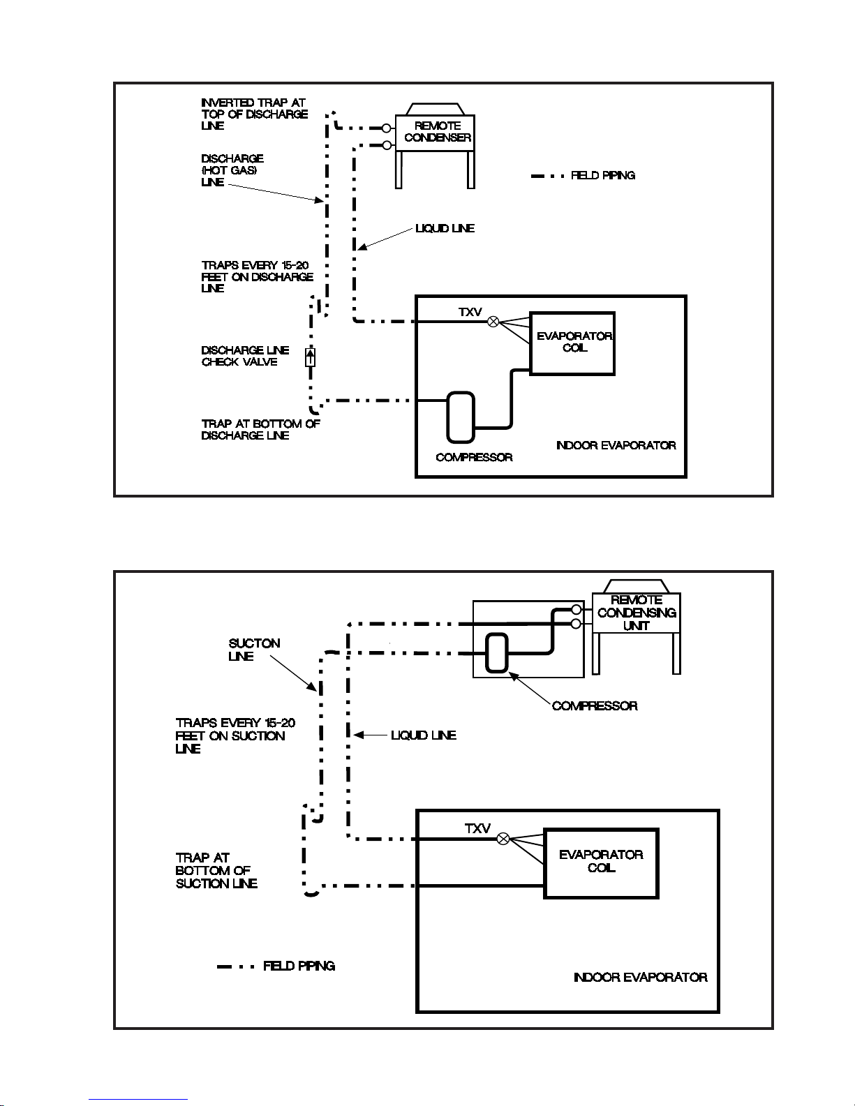
2.1.5 Field Piping, Remote Condenser
2.1.6 Field Piping, Remote Condensing Unit
11
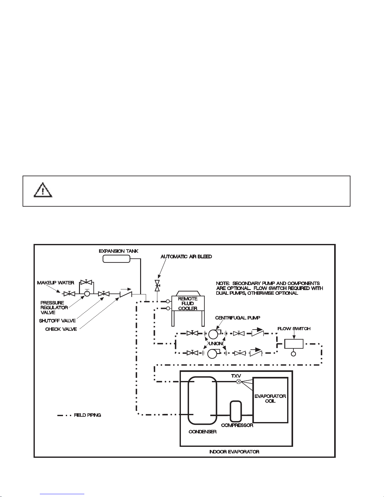
2.2 Water/Glycol Cooled Unit Piping
The required fi eld installed condenser water pipe sizes may or may not be the same as the connection
sizes at the evaporator or fl uid cooler . (Refer to 2.1.4 for connection sizing.) This will depend on the
length of pipe and the calculated pressure drop of peripheral components.
Water cooled units may also be connected to building water or tower water sources. Pipe size will
depend on length of run and the maximum water fl ow required.
Shutoff valves, fi eld provided, should be installed within a few feet of the inlet and outlet connections
of the evaporator to allow the unit to be isolated for service. There should be a means of draining the
unit for service. Drain/fi ll valves should be located at the lowest point on the connected piping.
All water/glycol units are shipped with plate/fi n heat exchangers as standard equipment. A strainer
is shipped loose and is to be fi eld installed in the supply line with shut-off valves, fi eld provided,
before and after the strainer. The strainers and water/glycol piping must be cleaned on a periodic
basis. If the unit is shipped with an optional shell and tube condenser, stainers are not required nor
shipped with the unit.
One of the most common problems in a water/glycol system is the presence of air in
the condenser water loop. Air vents must be installed in various locations in the piping
system to purge the air.
Glycol system piping may include a centrifugal pump (or pumps for redundancy). Pumps must be
primed before operating per the pump manufacturer’s guidelines.
(Field Provided)
12
 Loading...