

Page 1
Service Manual
DAEWOO DAT CO., LTD.
Model : XG-52x[V][K] Series
XG-53x[V][K] Series
XW-52x[K] Series
XW-53x[K] Series
SN : 9CD8304100
JUN. 2005
XG-52x[V][K] Series XG-53x[V][K] Series
XW-53x[K] Series
XW-52x[K] Series
Page 2

1
2
3
4
5
6
7
8
9
1
2
3
4
5
6
7
8
9
SAFETY PRECAUTIONS
.........................................................................................
1
ADJUSTMENTS
........................................................................................................
2
EXPLODED VIEW AND PARTS LIST
......................................................................
3
WIRING DIAGRAM
...................................................................................................
4
BLOCK DIAGRAM
....................................................................................................
5
SCHEMATIC DIAGRAM
...........................................................................................
6
CD Section
MP3/VCD Section
FRONT Section
TAPE and FUNCTION Section
AMP Section
MIC Section
POWER Section
PCB PATTERN LAYOUT
...........................................................................................
7
MAIN
AMP
FRONT
POWER
ELECTRICAL PART LIST
..........................................................................
Appendix
Table of Contents
Mi ni co mpo nen t sou nd sy ste m
wi t h CD-R / R W/MP3/V i d eo CD pl a y ba c k
XG-522[V]/524[V][K)/525[V][K)/526[V][K)/527[V][K)/528[V][K)
XG-532[V]/534[V][K)/535[V][K)/536[V][K)/537[V][K)//538[V][K)
Mi n i co m p o ne n t so u n d s y s t em
wi t h CD-R / R W p l ay b a ck
XW-522/524[K)/525[K)/526[K)/527[K)/528[K)
XW-532/534[K)/535[K)/536[K)/537[K)/538[K)
Page 3
Safety Precautions
1
2
3
4
5
6
7
8
9
1
2
3
4
5
6
7
8
9
WARNING
: TO PREVENT FIRE OR ELECTRIC SHOCK, DO NOT EXPOSE
THIS APPLIANCE TO RAIN OR MOISTURE.
CAUTION :
TO REDUCE THE RISK OF ELECTRIC SHOCK, DO NOT
REMOVE COVER (OR BACK). NO USER SERVICEABLE PARTS
INSIDE.
REFER SERVICING TO QUALIFIED SERVICE PERSONNEL.
THIS SYMBOL IS INTENDED TO ALERT THE USER TO THE
PRESENCE OF UNINSULTED "DANGEROUS VOLTAGE"
WITHIN THE PRODUCT'S ENCLOSURE THAT MAY BE
SUFFICIENT MAGNITUDE TO CONSTITUTE A RISK OF
ELECTRIC SHOCK TO PERSONS.
THIS SYMBOL IS INTENDED TO ALERT THE USER TO THE
PRESENCE OF IMPORTANT OPERATING AND MAINTENANCE
(SERVICING) INSTRUCTIONS IN THE LITERATURE
ACCOMPANYING THE APPLIANCE.
CAUTION
TO PREVENT ELECTRIC SHOCK, DO NOT USE THIS POLARIZED AC
PLUG WITH AN EXTENSION CORD, RECEPTACLE OR OTHER OUTLET
UNLESS THE BLADES CAN BE FULLY INSERTED TO PREVENT BLADE
EXPOSURE.
LASER SAFETY
THIS UNIT EMPLOYS A LASER. ONLY QUALIFIED SERVICE PERSONNEL
SHOULD REMOVE THE COVER OR ATTEMPT TO SERVICE THIS DEVICE
DUE TO POSSIBLE EYE INJURY.
CAUTION :
USE OF ANY CONTROLS, ADJUSTMENTS, OR PROCEDURES
OTHER THAN THOSE SPECIFIED HEREIN MAY RESULT IN HAZARDOUS
RADIATION EXPOSURE.
CAUTION :
TO PREVENT ELECTRIC SHOCK, MATCH WIDE BLADE OF
PLUG TO WIDE SLOT, FULLY INSERT.
ATTENTION :
POUR EVITER LES CHOCS ELECTRIQUES, INTRODUIRE
LA LAME LA PLUS LARGE DE LA FICHE DANS LA BORNE CORRESPONDANTE DE LA PRISE ET POUSSER JUSQU'AU FOND.
Important Safety Instructions
- All the safety and operating instructions should be read before
the appliance is operated.
- The safety and operating instructions should be retained for
future reference.
- All warnings on the appliance and in the operating instructions
should be adhered to.
- All operating and use instructions should be followed.
1. Water and Moisture - The appliance should not be used near
water - for example, near a bathtub, washbowl, kitchen sink,
laundry tub, in a wet basement, or near a swimming pool,
and the like.
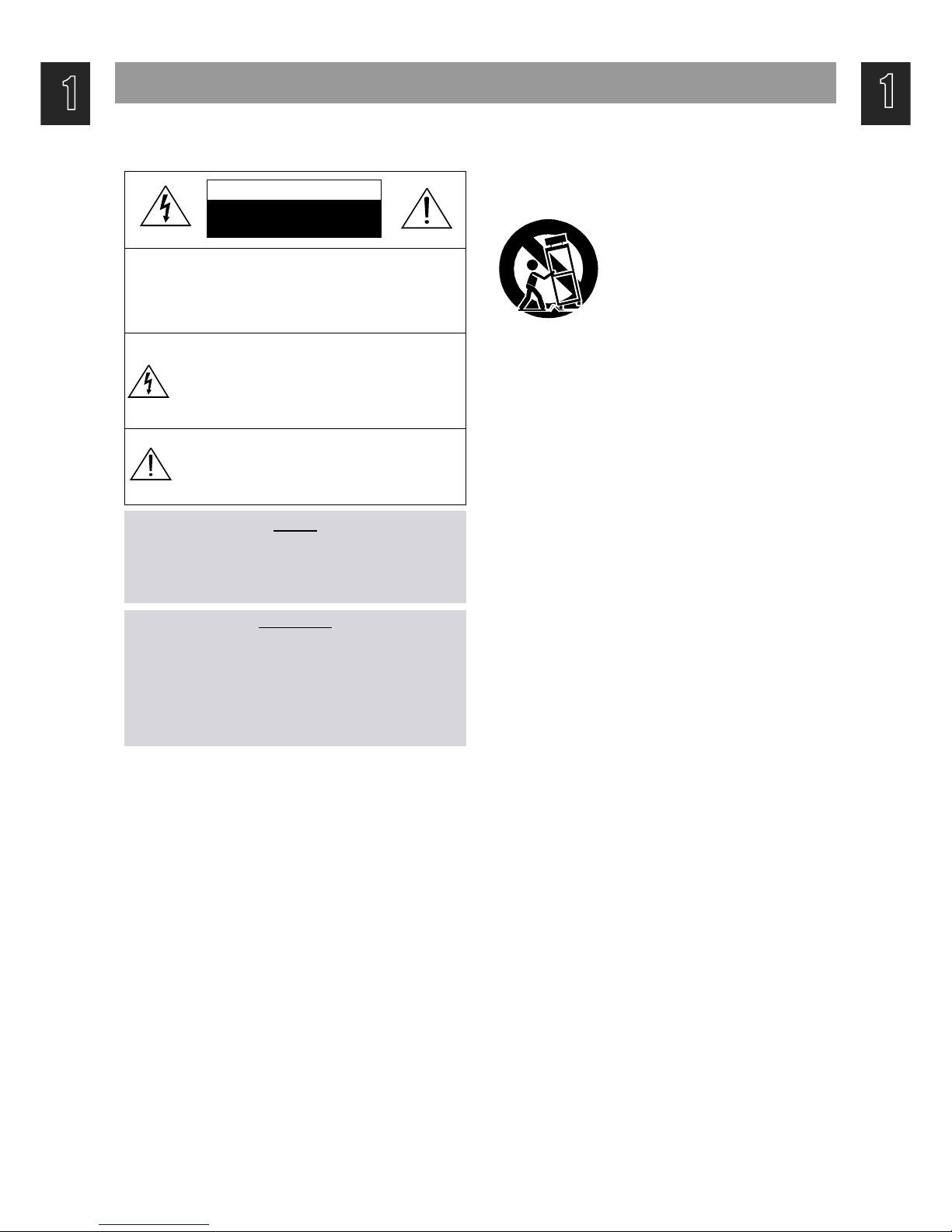
2. Carts and Stands - The appliance
should be used only with a cart or
stand that is recommended by th
manufacturer.
3. An appliance and cart combination
should be moved with care. Quick
stops, excessive force, and uneven
surfaces may cause the appliance
and cart combination to overturn.
4. Wall or Ceiling Mounting - The appli-
ance should be mounted to a wall or
ceiling only as recommended by the manufacturer.
5. Ventilation - The appliance should be situated so that its
location or position does not interfere with its proper
ventilation. For example, the appliance should not be situated
on a bed, sofa, rug, or similar surface that may block the
ventilation openings; or, placed in a built-in installation, such
as a bookcase or cabinet that may impede the flow of air
through the ventilation openings.
6. Heat - The appliance should be situated away from heat
sources such as radiators, heat registers, stoves, or other
appliances (including amplifiers) that produce heat.
7. Power Sources - The appliance should be connected to a
power supply only of the type described in the operating
instructions or as marked on the appliance.
8. Grounding or Polarization - The precautions that should be
taken so that the grounding or polarization means of an
appliance is not defeated.
9. Power - Cord Protection - Power-supply cords should be
routed so that they are not likely to be walked on or pinched
by items placed upon or against them, paying particular
attention to cords at plugs, convenience receptacles, and the
point where they exit from the appliance.
10.Protective Attachment Plug - If the appliance is equipped with
an attachment plug having overload protection. This is a
safety feature. See Instruction Manual for replacement or
resetting of protective device. If replacement of the plug is
required, be sure the service technician has used a
replacement plug specified by the manufacturer that has the
same overload protection as the original plug.
11.Cleaning - The appliance should be cleaned only as
recommended by the manufacturer.
12.Power Lines - An outdoor antenna should be located away
from power lines.
CAUTION
RISK OF ELECTRIC SHOCKS
DO NOT OPEN
PORTABLE CART
Figure 2
Page 4
1
2
3
4
5
6
7
8
9
Safety Precautions
1
2
3
4
5
6
7
8
9
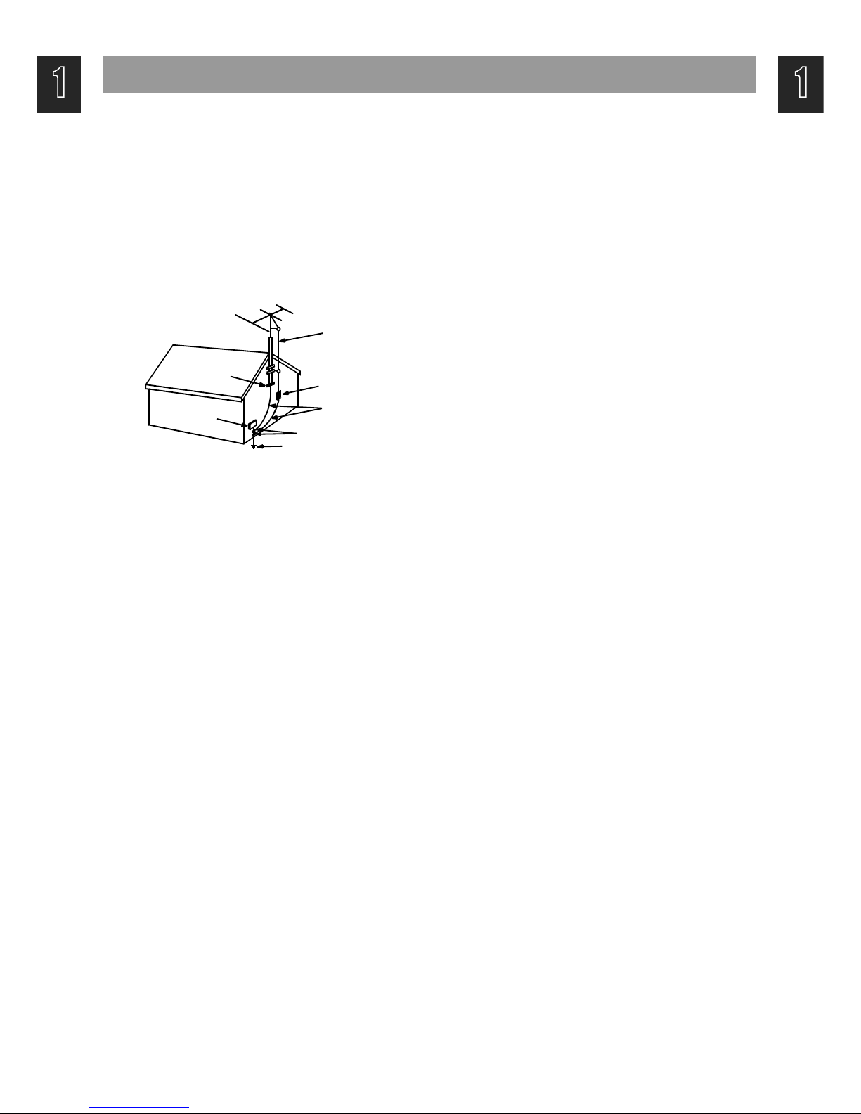
13.Outdoor Antenna Grounding - If an outside antenna is
connected to the receiver be sure the antenna system is
grounded so as to provide some protection against voltage
surges and built-up static charges. Article 810 of the National
Electrical Code, ANSI/NFPA 70, provides information with
regard to proper grounding of the mast and supporting
structure, grounding of the lead-in wire to an antenna-dis
charge unit, size of grounding conductors,location of antennadischarge unit, connection to grounding electrodes and
requirements for the grounding electrode. See Figure 1.
14.Non-use Periods - The power cord of the appliance should be
unplugged from the outlet when left unused for a long period
of time.
15.Object and Liquid Entry - Care should be taken so that objects
do not fall and liquids are not spilled into the enclosure through
openings.
16.Damage Requiring Service - The appliance should be
serviced by qualified service personnel when:
a) The power-supply cord or the plug has been damaged; or
b) Objects have fallen, or liquid has been spilled into the
appliance; or
c) The appliance has been exposed to rain; or
d) The appliance does not appear to operate normally or
exhibits a marked change in performance; or
e) The appliance has been dropped, or the enclosure
damaged.
17.Servicing - The user should not attempt to service the
appliance beyond that described in the operating instructions.
All other servicing should be referred to qualified service
personnel.
ANTENNA DISCHARGE UNIT
(NEC SECTION 810-20)
ANTENNA LEAD
IN WIRE
POWER SERVICE GROUNDING
ELECTRODE SYSTEM
(NEC ART 250 PART H)
GROUND CLAMP
ELECTRIC
SERVICE
EQUIPMENT
GROUNDING CONDUCTORS
(NEC SECTION 810-21)
GROUND CLAMPS
EXAMPLE OF ANTENNA
GROUNDING
NEC - NATIONAL ELECTRICAL CODE
Page 5
Adjustments
1
2
3
4
5
6
7
8
9
1
2
3
4
5
6
7
8
9
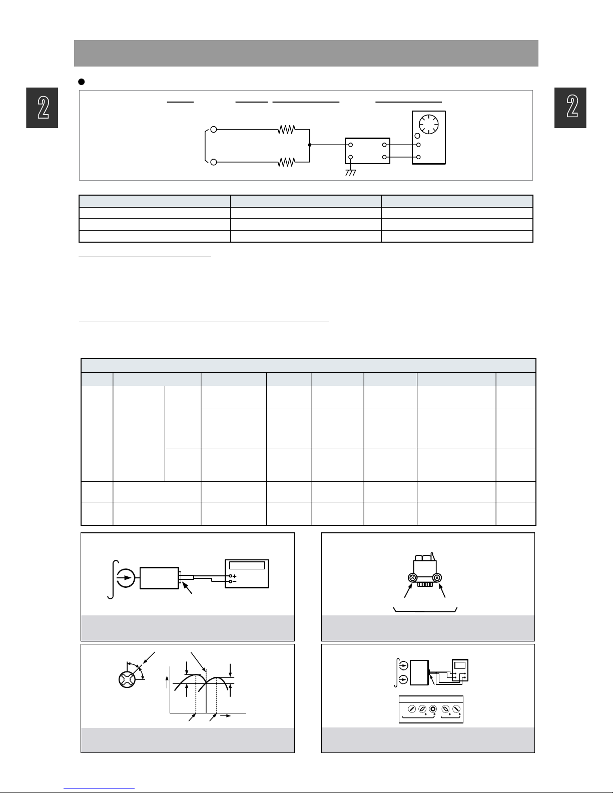
TAPE SECTION
Test Tape be used
HEAD ADJUSTMENT (AZIMUTH)
1. 10KHz test tape(example: MTT-114N) must be used for this adjustment.
2. Connect to VTVM or oscilloscope to the headphone jack or speaker terminal.
3. Press the play button.
4. Adjust the azimuth by using a screw driver to maintain the max. L&R output voltage.
5. Adjust tape A(1), tape B(2) respectively, Please secure the azimuth position by using locking paint.
RECORDING BIAS OSCILLATOR FREQUENCY ADJUSTMENT
1. Connect the frequency counter to TP603, GND.
2. Press the REC button.
3. Adjust L600 to obtain 80 KHz
±
500Hz
Tape Contents Use
MTT-111N 3 KHz Tape Speed Adjustment
MTT-114N 10 KHz Head Azimuth Adjustment
MTT-5511/ Blank Record Frequency Property
VTVM
Scope
R-CH
L-CH
47 kohm
47 kohm
Input Level
Measurement
Point
Input Point
Output Level
Measurement
Point
TAPE ALIGNMENT CHART
Step Item Reference Value Test Tape Adjust Point Test Point Note FIG.
1
Tape Speed
Adjustment
Normal
3,015~3,025Hz MTT-111N RV600
Line Out L/R
Channel
Line Out L/R
Channel
Confirm Wow & Flutter is within 0.35%
FIG.1
3,000~3,010Hz MTT-111N RV600
Line Out L/R
Channel
Confirm Tape Speed
of end position after
adjustment at tape
start position
FIG.1
High
5,820~6,180Hz MTT-111N - - - - - -
Confirm High speed
after normal speed
adjustment
FIG.1
2
Azimuth Adjustment
Maximum Level
Phase:Within90!
MTT-114N Head Screw
Line Out L/R
Channel
FIG.2,3,4
3
Recording Bias Oscillator
Frequency Adjustment
80 KHz
±0.5
MTT-5511
L600
TP603,GND
Adjust with frequency
counter connected.
FIG.1
FIG. 1 : Tape Speed & Record Bias Oscillator
Frequency Adjust Circuit
Test Tape : MTT-111N(3kHz)
MTT-5511(Blank)
Frequency Counter
Output Level
Measurement Point
Set
FIG. 2 : Tape Azimuth Adjust Location
(Record/Playback Head)
FIG. 3 : Tape Azimuth Adjust Head Screw & Waveform
FIG. 4 : Tape Azimuth Adjust Circuit & Waveform
Forward
Side
Reverse
Side
Adjust with Frequency
Counter Connected
L-CH
Peak
R-CH
Peak
Screw
Angle
Output Level
within
1 dB
within
1 dB
L-CH
Peak
R-CH
Peak
Screw Angle
V H
Oscilloscope
L-CH
Output Level
Measurement Point
Set
Test Tape
MTT-114N
(10kHz)
Screen Pattern
In Phase 45 90 135 180
Good Wrong
Page 6
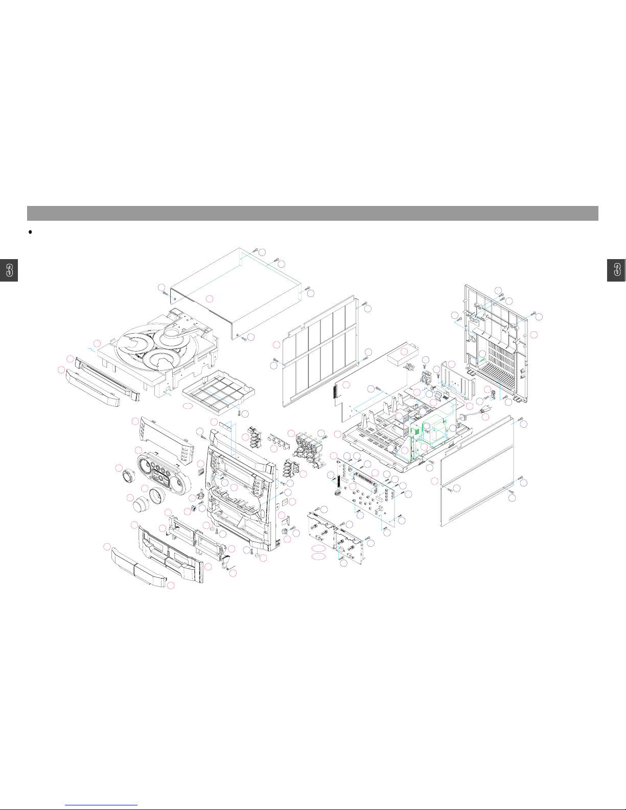
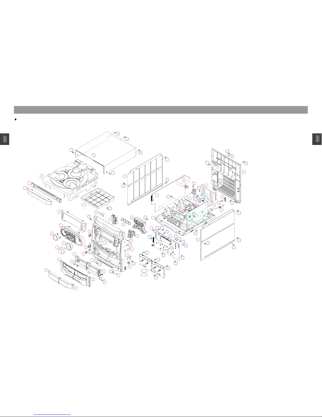
Exploded View and Mechanical Parts List
1
2
3
4
5
6
7
8
1
2
3
4
5
6
7
8
9
9
28
27-1
7
25
3
5
9
27-2
15
4
2
14
13
16
1
25
8
24
23
6
24
22
23
22
17
18
E1
20
19
32
P1
31
37
P4
10
12
26
11
OP1
21
P2
30
29
35
33
36
E4
P3
E3
E2
34
38
S1
S1
S1
S1
S4
S4
S7
S2
S2
S2
S2
S2
S2
S2
S1
S1
S2
S1
S1
S1
S1
S1
S1
S1
S1
S4
S2
S2
S4
S4
S3
S2
S4
S2
S4
S4
S4
S4
S3
S2
S2
S6
S4
S4
S3
S4
S4
S4
S2
S5
S4
S5
S2
XG-522[V] Model Only
Page 7

1
2
3
4
5
6
7
8
1
2
3
4
5
6
7
8
99
Exploded View and Mechanical Parts List
Page 8
Title
1
2
3
4
5
6
7
8
1
2
3
4
5
6
7
8
9
9
1
2
4
5
6
7
8
9
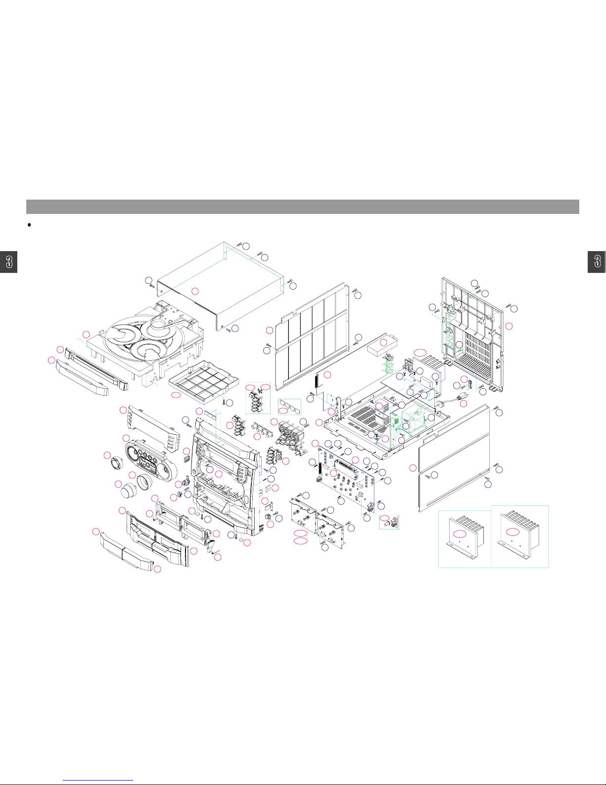
Exploded View and Mechanical Parts List
4
2
14
25
3
5
9
27-2
25
8
7
6
23
24
27-1
24
22
23
OP5
34-2
34-3
28
13
15
16
12
32
20
22
1
17
18
E1
19
P1
OP2
OP1
21
OP4
35
OP3
P2
26
11
10
30
29
31
36
33
E4
E3
E2
34-1
37
S4
S1
S1
S1
S1
S4
S4
S1
S2
S2
S2
S2
S2
S2
S2
S1
S2
S1
S1
S4
S4
S4
S1
S1
S1
S1
S1
S1
S2
S3
S4
S4
S3
S4
S5
S2
S6
S5
S3
S2
S3
S3
S4
S4
S4
S4
S4
S2
S3
S2
S5
S4
S5
S4
S3
S2
XG-525
XG-526
XG-524[V][K]/525[V][K]/526[V][K] Models Only
Page 9

1
2
3
4
5
6
7
8
1
2
3
4
5
6
7
8
99
Exploded View and Mechanical Parts List
Page 10
1
2
3
4
5
6
7
8
1
2
3
4
5
6
7
8
9
9
TitleExploded View and Mechanical Parts List
4
2
14
25
3
5
9
27-2
25
8
7
6
23
24
27-1
24
22
23
OP5
28
15
16
12
32
20
22
1
17
18
E1
19
P1
OP2
OP1
21
OP4
35
OP3
P2
26
11
10
30
29
31
36
33
E4
E3
E2
34-2
38
13-1
13-2
P3
P3
P4
37
34-1
37
S4
S1
S1
S1
S1
S4
S4
S1
S2
S2
S2
S2
S2
S2
S2
S1
S2
S1
S1
S4
S4
S4
S1
S1
S1
S1
S1
S1
S2
S3
S4
S4
S3
S4
S2
S6
S2
S4
S4
S4
S4
S4
S2
S3
S2
S5
S4
S5
S4
S3
S2
S2
S3
S2
S3
S3
S2
XW-527 / XG-527 [100W]
XG-527[V][K]/528[V][K]/XW-527[K]/528[K] Models Only
Page 11
3
1
2
3
4
5
6
7
8
9
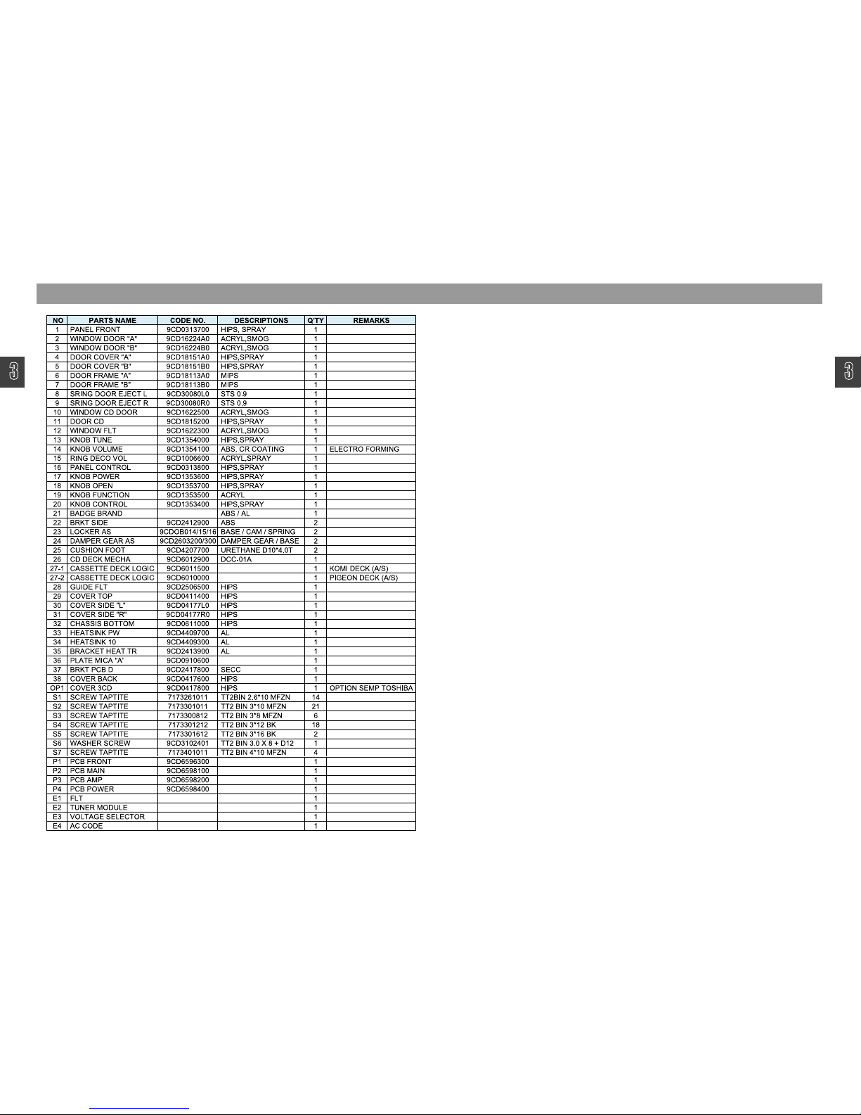
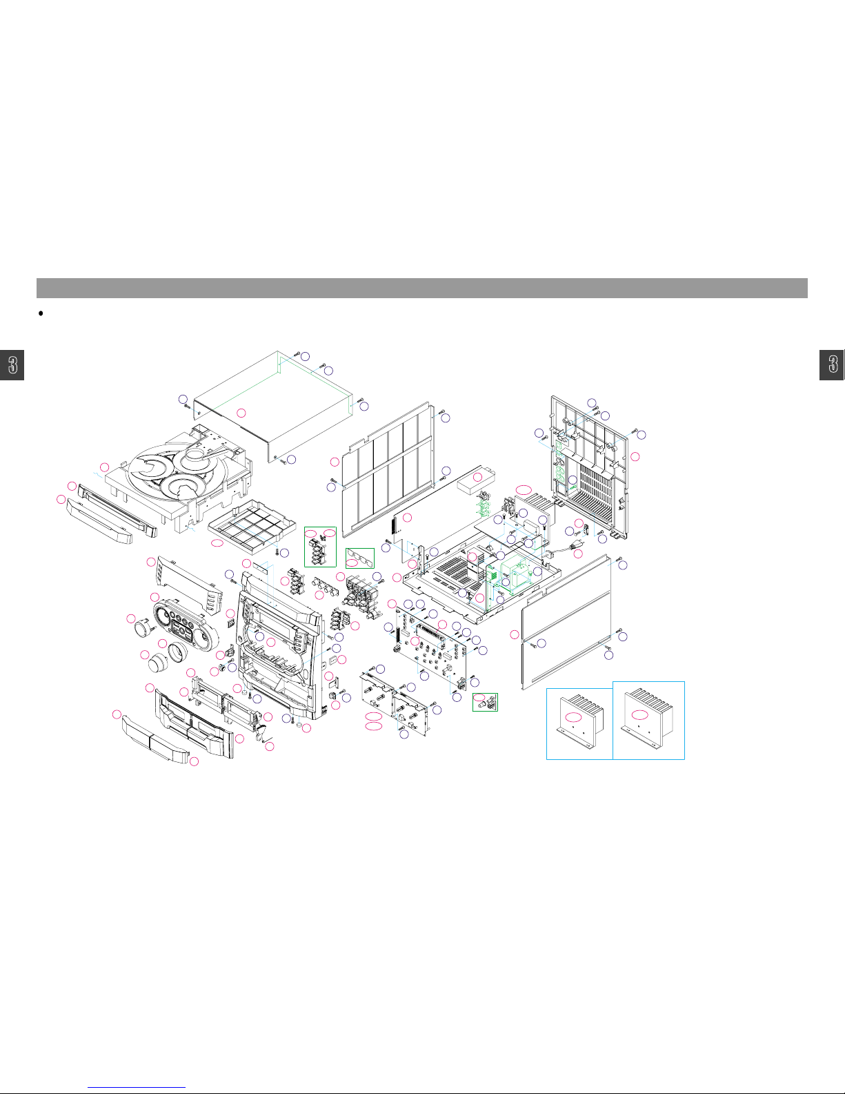
Exploded View and Mechanical Parts List
NO PARTS NAME CODE NO. DESCRIPTIONS Q'TY REMARKS
1 PANEL FRONT 9CD0313700 HIPS, SPRAY 1
2 WINDOW DOOR "A" 9CD16224A0 ACRYL, SMOG 1
3 WINDOW DOOR "B" 9CD16224B0 ACRYL, SMOG 1
4 DOOR COVER "A" 9CD18151A0 HIPS, SPRAY 1
5 DOOR COVER "B" 9CD18151B0 HIPS, SPRAY 1
6 DOOR FRAME "A" 9CD18113A0 MIPS 1
7 DOOR FRAME "B" 9CD18113B0 MIPS 1
8 SRING DOOR EJECT L 9CD30080L0 STS 0.9 1
9 SRING DOOR EJECT R 9CD30080R0 STS 0.9 1
10 WINDOW CD DOOR 9CD1622500 ACRYL, SMOG 1
11 DOOR CD 9CD1815200 HIPS, SPRAY 1
12 WINDOW FLT 9CD1622300 ACRYL, SMOG 1
13-1 KNOB TUNE 9CD1354000 HIPS, SPRAY 1 XW-527/528
13-2 KNOB JOG 9CD1355100 HIPS, SPRAY 1 XG-527/528
14 KNOB VOLUME 9CD1354100 ABS, CR COATING 1
15 RING DECO VOL 9CD1006600 ACRYL, SPRAY 1
16 PANEL CONTROL 9CD0313800 HIPS, SPRAY 1
17 KNOB POWER 9CD1353600 HIPS, SPRAY 1
18 KNOB OPEN 9CD1353700 HIPS, SPRAY 1
19 KNOB FUNCTION 9CD1353500 ACRYL 1
20 KNOB CONTROL 9CD1353400 HIPS, SPRAY 1
21 BADGE BRAND ABS / AL 1
22 BRKT SIDE 9CD2412900 ABS 2
23 LOCKER AS 9CDOB014/15/16 BASE / CAM / SPRING 2
24 DAMPER GEAR AS 9CD2603200/300 DAMPER GEAR / BASE 2
25 CUSHION FOOT 9CD4207700 URETHANE D10*4.0T 2
26 CD DECK MECHA 9CD6012900 DCC-01A 1
27-1 CASSETTE DECK LOGIC 9CD6011500 1 KOMI DECK (A/S)
27-2 CASSETTE DECK LOGIC 9CD6010000 1 PIGEON DECK (A/S)
28 GUIDE FLT 9CD2506500 HIPS 1
29 COVER TOP 9CD0411400 HIPS 1
30 COVER SIDE "L" 9CD04177L0 HIPS 1
31 COVER SIDE "R" 9CD04177R0 HIPS 1
32 CHASSIS BOTTOM 9CD0611400 SECC 1
33 HEATSINK PW 9CD4409700 AL 1
34-1 HEATSINK AMP 100 9CD4410500 AL H=40mm 1 XW-527 / XG-527
34-2 HEATSINK AMP 150 9CD4410400 AL H=60mm 1 XW-528 / XG-528
35 BRKT PCB C 9CD2414500 SECC 2
36 BRKT PCB D 9CD2417800 SECC 1
37 PLATE PCB AMP 9CD0914600 PC T0.5 1
38 COVER BACK 9CD0417600 HIPS 1
OP1 COVER 3CD 9CD0417800 HIPS 1 OPTION SEMP TOSHIBA
OP2 KNOB POWER 9CD1354800 HIPS, SPRAY 1 OPTION STANDBY LED
0P3 LENS POWER 9CD1622600 ACRYL, MILKY 1 OPTION STANDBY LED
OP4 FUNCTION PLATE 9CD0913800 PC T0.15 1 OPTION FUNCTION LED
OP5 KNOB MIC 9CD1354900 HIPS, SPRAY 1 OPTION KARAOKE
NO PARTS NAME CODE NO. DESCRIPTIONS Q'TY REMARKS
S1 SCREW TAPTITE 7173261011 TT2BIN 2.6*10 MFZN 14
S2 SCREW TAPTITE 7173301011 TT2 BIN 3*10 MFZN 24
S3 SCREW TAPTITE 7173301612 TT2 BIN 3*6 MFZN 10
S4 SCREW TAPTITE 7173301212 TT2 BIN 3*12 BK 18
S5 SCREW TAPTITE 7173301612 TT2 BIN 3*16 BK 2
S6 SCREW TAPTITE 7173400611 TT2 BIN 4*6 MFZN 4
P1 PCB FRONT 9CD6596300 1
P2 PCB MAIN 9CD6598100 1
P3 PCB AMP 9CD6500600 1
P4 PCB POWER 9CD6598400 1
E1 FLT 1
E2 TUNER MODULE 1
E3 VOLTAGE SELECTOR 1
E4 AC CODE 1
Page 12
1
2
3
4
5
6
7
8
1
2
3
4
5
6
7
8
9
9
Exploded View and Mechanical Parts List
2
3
4
5
6
7
14
15
13
16
12
10
11
21
26
29
1
22
23
24
25
25
24
23
22
27-1
17
19
20
18
P1
30
31
P2
E2
33
P4
P3
35
34
E3
E4
32
38
8
9
36
28
E1
27-2
OP1
37
S2
S2
S2
S2
S2
S2
S2
S2
S2
S2
S2
S1
S5
S5
S4
S4
S4
S4
S4
S4
S4
S4
S4
S4
S1
S1
S1
S1
S1
S1
S1
S1
S1
S1
S1
S3
S2
S3
S3
S4
S4
S2
S2
S4
S7
S1
S1
S2
S4
S6
S4
S4
S2
XW-522 Model Only
Page 13
1
2
3
4
5
6
7
8
1
2
3
4
5
6
7
8
99
Exploded View and Mechanical Parts List
Page 14
Title
1
2
3
4
5
6
7
8
1
2
3
4
5
6
7
8
9
9
1
2
4
5
6
7
8
9
Exploded View and Mechanical Parts List
33
E4
2
10
11
26
27-1
7
3
9
5
25
27-2
24
1
15
4
8
14
24
23
6
25
23
22
13
16
17
19
22
18
E1
20
32
P1
28
31
12
21
30
P2
E2
29
E3
37
34-1
35
34-2
34-3
OP2
OP3
OP5
OP4
OP1
36
S3
S3
S3
S5
S5
S6
S2
S2
S1
S1
S1
S1
S4
S4
S2
S2
S1
S2
S2
S1
S2
S2
S2
S2
S1
S1
S1
S1
S1
S1
S1
S1
S4
S4
S2
S4
S4
S4
S4
S4
S4
S4
S4
S4
S2
S4
S5
S2
S4
S5
S4
S3
S3
S3
S2
S3
XW-526
XW-525
XW-524[K]/525[K]/526[K] Models Only
Page 15

1
2
3
4
5
6
7
8
1
2
3
4
5
6
7
8
99
Exploded View and Mechanical Parts List
Page 16

Exploded View and Mechanical Parts List
1
2
3
4
5
6
7
8
1
2
3
4
5
6
7
8
9
9
2
3
4
5
6
7
17
12
10
11
24
29
32
1
25
26
27
28
28
27
26
25
30-1
18
19
P1
33
34
P2
E2
36
P4
P3
38
37
E3
E4
35
40
8
9
39
31
E1
30-2
OP1
14
15
16
13
20
21
22
23
41
13-1
13-2
S2
S2
S3
S3
S2
S2
S2
S2
S2
S2
S2
S5
S5
S4
S4
S4
S4
S4
S4
S4
S4
S4
S4
S1
S1
S1
S1
S1
S1
S1
S1
S1
S1
S1
S2
S3
S3
S4
S4
S2
S2
S4
S7
S1
S1
S2
S4
S6
S4
S4
S1
S1
S3
S2
XG VER.
XG-532[V]/XW-532 Models Only
Page 17

1
2
3
4
5
6
7
8
1
2
3
4
5
6
7
8
99
Exploded View and Mechanical Parts List
Page 18

Title
1
2
3
4
5
6
7
8
1
2
3
4
5
6
7
8
9
9
1
2
3
4
5
6
7
8
9
Exploded View and Mechanical Parts List
36
E4
2
10
11
29
30-1
7
3
9
5
28
30-2
27
1
4
8
27
26
6
28
26
25
18
25
19
E1
35
P1
31
34
12
24
33
P2
E2
32
E3
40
37-1
39
38
37-2
37-3
OP2
OP3
OP5
OP4
OP1
14
15
16
17
20
21
22
23
13-1
13-2
13
S3
S3
S3
S6
S6
S7
S3
S3
S1
S1
S1
S1
S5
S5
S3
S2
S1
S2
S3
S1
S2
S2
S2
S2
S1
S1
S1
S1
S1
S1
S5
S5
S2
S5
S5
S5
S5
S5
S4
S5
S5
S5
S2
S5
S6
S2
S5
S6
S5
S4
S4
S4
S4
S2
S1
S1
S1
XW/XG-536
XW/XG-534
XG VER.
XG-534[V][K]/535[V][K]/536[V][K], XW-534[K]/535[K]/536[K] Models Only
Page 19

1
2
3
4
5
6
7
8
1
2
3
4
5
6
7
8
99
Exploded View and Mechanical Parts List
Page 20

1
2
3
4
5
6
7
8
1
2
3
4
5
6
7
8
9
9
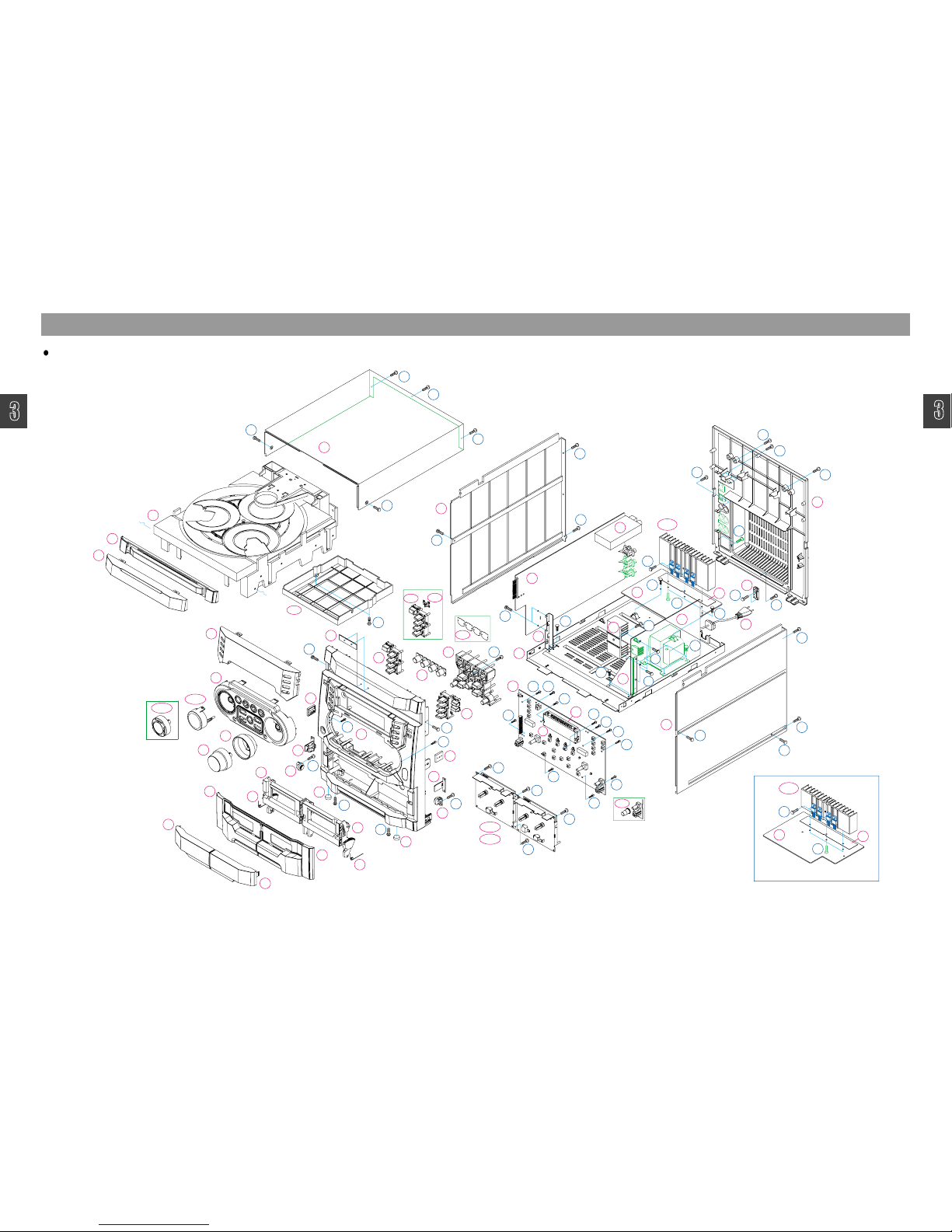
TitleExploded View and Mechanical Parts List
36
E4
2
10
11
29
30-1
7
3
9
5
28
30-2
27
1
4
8
27
26
6
28
26
25
18
25
19
E1
35
P1
31
34
12
24
33
P2
E2
32
E3
41
37-2
39
38
OP2
OP3
OP5
OP4
OP1
14
15
16
17
20
21
22
23
13-1
13-2
13
P3
P4
40
P3
37
37-1
S7
S3
S3
S1
S1
S1
S1
S5
S5
S3
S2
S1
S2
S3
S1
S2
S2
S2
S2
S1
S1
S1
S1
S1
S1
S5
S5
S2
S5
S5
S5
S5
S5
S4
S5
S5
S5
S2
S5
S6
S2
S5
S6
S5
S4
S4
S4
S4
S2
S1
S1
S1
S2
S2
S4
S4
S3
S2
XG VER.
XW-537 / XG-537 [100W]
XG-537[V][K]/538[V][K], XW-537[K]/538[K] Models Only
Page 21

1
2
3
4
5
6
7
8
1
2
3
4
5
6
7
8
99
Exploded View and Mechanical Parts List
NO PARTS NAME CODE NO. DESCRIPTIONS Q'TY REMARKS
1 PANEL FRONT 9CD0313700 HIPS, SPRAY 1
2 WINDOW DOOR "A" 9CD16224A0 ACRYL,SMOG 1
3 WINDOW DOOR "B" 9CD16224B0 ACRYL,SMOG 1
4 DOOR COVER "A" 9CD18151A0 HIPS,SPRAY 1
5 DOOR COVER "B" 9CD18151B0 HIPS,SPRAY 1
6 DOOR FRAME "A" 9CD18113A0 MIPS 1
7 DOOR FRAME "B" 9CD18113B0 MIPS 1
8 SRING DOOR EJECT L 9CD30080L0 STS 0.9 1
9 SRING DOOR EJECT R 9CD30080R0 STS 0.9 1
10 WINDOW CD DOOR 9CD1622500 ACRYL,SMOG 1
11 DOOR CD 9CD1815200 HIPS,SPRAY 1
12 WINDOW FLT 9CD1622300 ACRYL,SMOG 1
13 KNOB TUNING 9CD1354600 HIPS,SPRAY 1 XW-537/538
13-1 KNOB JOG 9CD1354500 HIPS,SPRAY 1 XG-537/538
13-2 DECO JOG 9CD1006800 ACRYL,SMOG 1 XG-537/538
14 KNOB VOLUME 9CD1354700 ABS, CR COATING 1
15 DECO VOL 9CD1006700 ACRYL,SPRAY 1
16 DECO RING 9CD1006900 ABS, CR COATING 1
17 PANEL CONTROL 9CD0314200 HIPS,SPRAY 1
18 KNOB POWER 9CD1354800 HIPS,SPRAY 1
19 KNOB OPEN 9CD1353700 HIPS,SPRAY 1
20 DECO FUNCTION 9CD1007000 ABS, CR COATING 1
21 KNOB FUNCTION 9CD1354300 ACRYL 1
22 KNOB PRESET 9CD1354400 ACRYL 1
23 KNOB CONTROL 9CD1354200 HIPS,SPRAY 1
24 BADGE BRAND ABS / AL 1
25 BRKT SIDE 9CD2412900 ABS 2
26 LOCKER AS 9CDOB014/15/16 BASE / CAM / SPRING 2
27 DAMPER GEAR AS 9CD2603200/300 DAMPER GEAR / BASE 2
28 CUSHION FOOT 9CD4207700 URETHANE D10*4.0T 2
29 CD DECK MECHA 9CD6012900 DCC-01A 1
30-1 CASSETTE DECK LOGIC 9CD6011500 1 KOMI DECK (A/S)
30-2 CASSETTE DECK LOGIC 9CD6010800 1 PIGEON DECK (A/S)
31 GUIDE FLT 9CD2506500 HIPS 1
32 COVER TOP 9CD0411400 HIPS 1
33 COVER SIDE "L" 9CD04177L0 HIPS 1
34 COVER SIDE "R" 9CD04177R0 HIPS 1
35 CHASSIS BOTTOM 9CD0611400 SECC 1
36 HEATSINK PW 9CD4409700 AL 1
37-1 HEATSINK AMP 100 9CD4410500 AL H=40mm 1 XW-537 / XG-537
37-2 HEATSINK AMP 150 9CD4410400 AL H=60mm 1 XW-538 / XG-538
38 BRKT PCB C 9CD2414500 SECC 1
39 BRKT PCB D 9CD2417800 SECC 1
40 PLATE PCB AMP 9CD0914600 PC T0.5 1
41 COVER BACK 9CD0417600 HIPS 1
OP1 COVER 3CD 9CD0417800 HIPS 1 OPTION SEMP TOSHIBA
OP2 KNOB POWER 9CD1354800 HIPS, SPRAY 1 OPTION STANDBY LED
0P3 LENS POWER 9CD1622600 ACRYL, MILKY 1 OPTION STANDBY LED
OP4 FUNCTION PLATE 9CD0913800 PC T0.15 1 OPTION FUNCTION LED
OP5 KNOB MIC 9CD1354900 HIPS, SPRAY 1 OPTION KARAOKE
NO PARTS NAME CODE NO. DESCRIPTIONS Q'TY REMARKS
P1 PCB FRONT 9CD6598000 1
P2 PCB MAIN 9CD6599000 1
P3 PCB AMP 9CD6500600 1
P4 PCB POWER 9CD6599200 1
E1 FLT 1
E2 TUNER MODULE 1
E3 VOLTAGE SELECTOR 1
E4 AC CODE 1
S1 SCREW TAPTITE 7173261011 TT2BIN 2.6*10 MFZN 15
S2 SCREW TAPTITE 7173301011 TT2 BIN 3*10 MFZN 20
S3 SCREW TAPTITE 7173300812 TT2 BIN 3*8 MFZN 6
S4 SCREW TAPTITE 7173301612 TT2 BIN 3*6 MFZN 6
S5 SCREW TAPTITE 7173301012 TT2 BIN 3*10 BK 18
S6 SCREW TAPTITE 7173301612 TT2 BIN 3*16 BK 2
S7 SCREW TAPTITE 7173400611 TT2 BIN 4*6 MFZN 4
Page 22

Title
1
2
3
4
5
6
7
8
1
2
3
4
5
6
7
8
9
9
Wiring Diagram
Page 23

1
2
3
4
5
6
7
8
1
2
3
4
5
6
7
8
99
Title
1
2
3
5
6
7
8
1
2
3
6
7
8
99
Block Diagram
Page 24

Schematic Diagram
1
2
3
4
5
6
7
8
1
2
3
4
5
6
7
8
9
9
CD Section
Page 25

1
2
3
4
5
6
7
8
1
2
3
4
5
6
7
8
99
Schematic Diagram
MP3/VCD Section : XG-52x[V][K]/XG-53x[V][K] Series Only
Page 26

Schematic Diagram
1
2
3
4
5
6
7
8
1
2
3
4
5
6
7
8
9
9
Front Section : XG-52x[V][K]/XW-52x[K] Series Only
Page 27

1
2
3
4
5
6
7
8
1
2
3
4
5
6
7
8
99
Schematic Diagram
Front Section : XG-53x[V][K]/XW-53x[K] Series Only
Page 28

Title
1
2
3
4
5
6
7
8
1
2
3
4
5
6
7
8
9
9
Schematic Diagram
TAPE and Function Section
Page 29

1
2
3
4
5
6
7
8
1
2
3
4
5
6
7
8
99
Schematic Diagram
AMP Section : XG-522[V]/532[V], XW-522/532 Models only
Page 30

Schematic Diagram
1
2
3
4
5
6
7
8
1
2
3
4
5
6
7
8
9
9
AMP Section : XG-524[V][K]/525[V][K]/526[V][K]/534[V][K]/535[V][K]/536[V][K], XW-524[K]/525[K]/526[K]/534[K]/535[K]/536[K] Models only
Page 31

1
2
3
4
5
6
7
8
1
2
3
4
5
6
7
8
99
Schematic Diagram
Digital AMP Section : XG-527[V][K]/528[V][K]/537[V][K]/538[V][K], XW-527[K]/528[K]/537[K]/538[K] Models only
Page 32

Title
1
2
3
4
5
6
7
8
1
2
3
4
5
6
7
8
9
9
Schematic Diagram
MIC Section : Karaoke Models only
Page 33

Schematic Diagram
1
2
3
4
5
6
7
8
1
2
3
4
5
6
7
8
9
9
POWER Section
Q906
1
09DH
3PMo/w
4285C
919RH
mhO01
mhO0
evaS-Pw
3PMw
Y8502D
029RH
roW56-W5.21
W051/W001roFDFVegraL
evaS-Po/w
W051/W001roFDFVllamS
199WS
00202AHKDS
Page 34

P.C.B Pattern Layout
1
2
3
4
5
6
7
8
1
2
3
4
5
6
7
8
9
9
MAIN
<Top View>
Page 35

1
2
3
4
5
6
7
8
1
2
3
4
5
6
7
8
99
P.C.B Pattern Layout
MAIN
<Bottom View>
Page 36

P.C.B Pattern Layout
1
2
3
4
5
6
7
8
1
2
3
4
5
6
7
8
9
9
AMP Section <Top View>
<XG-522[V]/532[V], XW-522/532 Models Only>
<
XG-524[V][K]/525[V][K]/526[V][K]/534[V][K]/535[V][K]/536[V][K],
XW-524[K]/525[K]/526[K]/534[K]/535[K]/536[K] Models Only>
Page 37

1
2
3
4
5
6
7
8
1
2
3
4
5
6
7
8
99
P.C.B Pattern Layout
HC832
HC821
HC813
3875/N
HQ808
HR809
HZ804
HR845
HR804
HC855
HC808
CE805
A06/N
HQ802
HR851
HR850
HR846
HR841
HR836
HR834
HR827
HC845
HC842
HC841
HC840
HC836
NC
NC
HZ801
HR802
HC886
HR822
HR814
HC834
HC829
HC826
HC825
HC823
HC819
HC815
HC801
HQ804
HR801
HC806
S
HC854
HC804
HR880
CE804
HQ803
HC835
HC858
HZ802
1504/P
A56/P
1504/P
HQ807
3875/N
HQ805
3875/N
HR807
HC831
HR805
HR803
CE803
HR854
HR849
HR839
HR816
HR819
HR810
VO
HR905
HR837HR835
HR833
HR832
HR831
HR830
HR828
HR826
HR825
HR823
HR847
HR808
CM817
HR840
HR812
HR806
HR852
HQ801
1504/P
HR856
HQ806
HC879
HC809
CE827
HR824
HC880
CE888
HC814
HC867
S
+5V
GND
HR868
HR855
HR858
HC856
L801
B-
FRQ-
HR842
CE874
L802
CE860
HR893
CE852
HR821
9CD6500600
CE848
G
2005/06/09 VER1.0
R-
R+
L-
L+
HQ829
WAVE
CE838
HR886
HD813
3875/N
HQ815
HC844
HC887
CE837
HR872
HC881
B+
HR870
-5V
3875/N
HQ813
HR844
HR887
HR863
HR859
HR891
HR882
HR879
HC870
HC818
HC875
HC869
HR881
HQ827
HR865
HC876
HC810
3875/N
HQ814
R829
HQ819
HR818
1
4
VO
VI
J801
L7805
IC804
TRIANGLE
1504/P
HR897
HR899HR898
HR892
HR829
3875/N
HQ817
HR894
HR896
3875/N
HQ818
HR817
HC816
+5V
HR864
3875/N
10
1
CW802
SEN
MUTE
+12V
L_IN GND R_IN
S
3875/N
G
FQPF15P12
FQPF15P12
Q801
S
G
FQPF16N15
FQPF16N15
Q804
HR915
CW801
G
Q803
HC872
HC847
HC830
HC884
HR813
HR843
HC812
HC882
B+
B+
GND
PRO-
HC822
HR914
R817
R848
CE859
HC850
HC807
HC817
+
HC839
HC802
HC883
HC803HC859
HC827
HC805
CM820
CE861
+
CE833
CE814
HR900
HD805
GNDGND
HD812
HQ820
R+*
-5V
HD811
A111S
CE801
-12V
HC811
HC871
HC846
R816
R847
HC848
HC849
HC852
HC851
GND
L7905
IC803
HZ803
B+
B-
1
L+
CW803
4
R+
L-
+
+
CE802
+
CE858
R-
HR908
HR910
R-
3875/N
HQ823
HC894
B+
1504/P
HQ824
HR906
HQ825
HR907
HC893
CM849
HQ826
HR909
HQ828
HR912
HR838
HC895
HR913
9
1
HR901
1504/P
HQ809
HR815
HR902
HC853
HD814
HR895
DIGITALXG-547/8 AMP
R853
TECT
CM851
16
9
8
1
IC802
NC
48
25
24
1
IC801
S/N
:
NC
CM818
CM821
CM823
CM824
CM819
CM822
NC
NC
PCB FIX PAD
PCB FIX PAD
HR871
HC885
HR874
P-CH N-CH
B+
GND
VI
+12V
-12V
B+
TH801
HC857
HR853
HC873
1504/P
HQ811
HR811
3875/N
HQ812
HR857
HR848
N
+
CE807
56
06
A
N
N
P
N
P
P
P
N
N
N
P
N
P
N
N
P
N
P
N
N
N
EMT2
EMX2
EMT2
1
1
1
NC
CE806
Q802
NC
9
16
IC805
7
1
NC
DIGITAL AMP : XG-527[V][K]/528[V][K]/537[V][K]/538[V][K], XW-527[K]/528[K]/537[K]/538[K] Models only
<Top View>
VI
CM817
JACKSPK-4P
CE805
VO
L-
G
GND
B-
G
B-
B-
L+*
+
CE804
+
PROTECT
CE803
CE827
FQPF15P12
CE888
L801
CE874
CE860
CE852
J801
AVOID2
B-
CE848
FQPF16N15
2005/06/09 VER1.0
R- R+
L-
L+
FRQ
CE838
SEN
MUTE
+12V
+5V
-12V
-5V
AVOID1
+5V
L7805
VI
CE859
CE837
Q804
L_INGNDR_IN
TC16B-09
TC16B-09L802
GND
-12V
PRO-
FRQ
S
G
S
GND
FQPF15P12
Q801
S
G
FQPF16N15
VO
TRIANGLE
B+
B+
CM849
R817
R848
Q802
CE861
-5V
CE833
CE814
B+NC
NC
B+
-5V
+5V
B-
CM820
R816
R847
L7905
GND
:
B-
L-
R-
R+
L+
+
CE801
+
CE802
+
CE858
B+
B-
GND
GND
XG-547/8 DIGITALS/N 9CD6500600
R853
R829
CM851
AMP
CM818
CM821
CM823
CM824
CM819
CM822
GND
+12V
B+ GND
B-
-5V
+5V
R-
+R*
L-
L+*
R-NCH-GATE
R-PCH-GATE
L-NCH-GATE L-PCH-GATE
PWM-OFF-MUTE
R_IN
GND
L_IN
MUTE
WAVE
S1A0071-4PIN
B+
B-
SEN
TH801
+
CE807
NC
TECT
CE806
Q803
S
<Bottom View>
Page 38

1
2
3
4
5
6
7
8
1
2
3
4
5
6
7
8
9
9
TitleP.C.B Pattern Layout
FRONT : XG-52x[V][K], XW-52x[K] Series Models Only
<Top View>
Page 39

1
2
3
4
5
6
7
8
1
2
3
4
5
6
7
8
99
P.C.B Pattern Layout
FRONT : XG-52x[V][K], XW-52x[K] Series Models Only
<Bottom View>
Page 40

Title
1
2
3
4
5
6
7
8
1
2
3
4
5
6
7
8
9
9
P.C.B Pattern Layout
FRONT : XG-53x[V][K], XW-53x[K] Series Models Only
<Bottom View>
Page 41

1
2
3
4
5
6
7
8
1
2
3
4
5
6
7
8
99
TitleP.C.B Pattern Layout
1
2
3
4
5
6
8
9
FRONT : XG-53x[V][K], XW-53x[K] Series Models Only
<Bottom View>
Page 42

0 1 2 3 4 5 6
1
2
3
4
5
6
7
8
1
2
3
4
5
6
8
99
P.C.B Pattern Layout
7
POWER
<Top View>
<Bottom View>
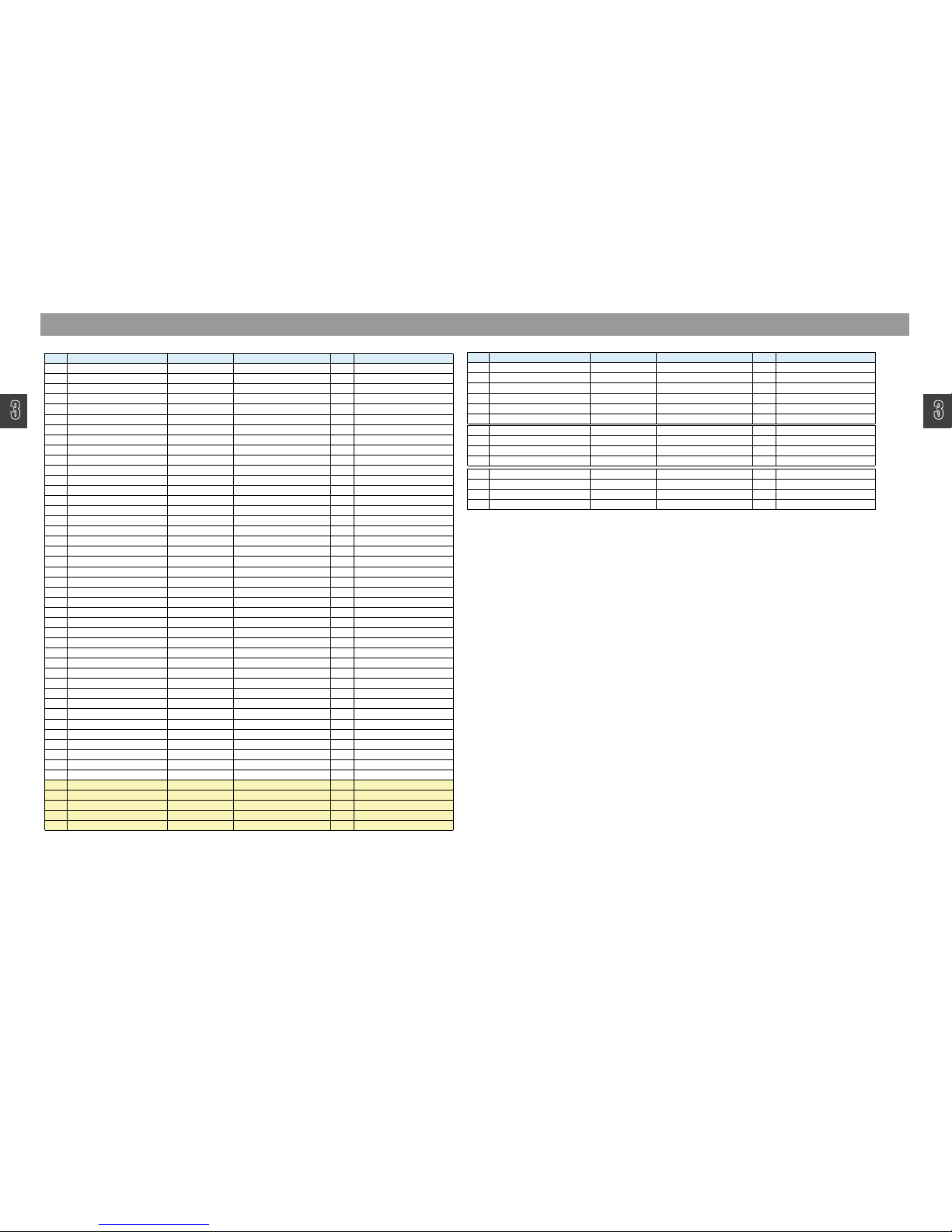
Page 43

Location Part Code Part Name Description Remark
FD701 DHNA11MS26 VFD HNA-11MS26
HD351 HD352 HD353 HD381
HD701 HD702 HD703 HD704
HD705 HD706 HD707 HD712
HD713
DZDS160--- DIODE SW CHIP KDS160(KDS511)
HQ351 HQ352 HQ353 HQ704 TZTC3875S- TR CHIP KTC3875Y
HQ381 HQ382 HQ385 HQ702
HQ703
TZRC111S-- TR CHIP KRC111S
HQ383 HQ384 TZTD1304-- TR CHIP KTD1304
HQ387 HQ711 HQ712 HQ713
HQ714 HQ715
TZRA111S-- TR CHIP KRA111S
HQ701 HQ708 HQ709 HQ710
HQ716 HQ717 HQ718 HQ720
HQ721
TZRC107S-- TR CHIP KRC107S
HQ705 HQ706 HQ707 T2SA2071-- TR CHIP 2SA2071
HQ719 TZRA107S-- TR CHIP KRA107S
IC351 1NJM4558M- IC NJM4558M Karaoke model only
IC381 1BA4560F-- IC H/P AMP BA4560F
IC701 13776522V- IC U-COM M3776AMCH-1B9GP
IC702 1M24C04MN- IC EEPROM M24C04MN SOP
IC704 1F4094BM1T IC HCF4094M013TR
IC705 1HK381B-DW IC PRE AMP HK381BT-DW
IC706 1PT6315--- IC PT6315
J351 J701 9736325300 JACK H/P HTJ-035-18A
LD701 LD702 LD704 LD705
LD707 LD708 LD710 LD711
DSLR332MC3F LED SLR332MC3F(GREEN)PI3
LD703 LD706 LD709 LD712
LD715
DSLR332VC3F LED SLR332VC3F(RED)PI3
LD713 LD714 LD716 LD717 DMT-463UBD LED MT-463UBD/W60
SW701 SW702 SW703 SW704
SW705 SW706 SW708 SW709
SW710 SW713 SW714 SW715
SW716 SW719 SW720 SW721
SW722 SW723 SW724 SW725
SW730
5S50101Z67 SW TACT SKHV 10920A, 5MM
SW728 5S50101001 SW TACT KPT-1105A 1C-1P
VR351 5V1503730B VOL MIC XV09211NPV20F1-B50K
VR701 5SH1224375 SW ENCODER RE0123PVB25FINB 1-2-24 PCE
VR702 5SH1224379 SW ENCODER RE012308PVB25FINB1-2-24 PCE XG-53 series
VR702 5SH1224375 SW ENCODER RE0123PVB25FINB 1-2-24 PCE XG-52 series
VR351 5V1503730B VOL MIC XV09211NPV20F1-B50K
XC701 5XJ16R000C X-TAL JWT-16.000-US
Location Part Code Part Name Description Remark
D501 DIN4001--- DIODE IN4001
DZ506 DZTZ3R3B-- DIODE ZENER MTZ-3.3B 52MM TAPPING
HD401 HD402 HD500 HD501
HD502 HD641 HD642
DZDS160--- DIODE SW CHIP KDS160(KDS511)
HQ573 HQ574 HQ643 HQ644 TZTA1504S- TR CHIP KTA1504S
HQ601 HQ602 TZTC3875S- TR CHIP KTC3875Y
HQ603 HQ604 HQ642 TZRC111S-- TR CHIP KRC111S
HQ641 TZRA107S-- TR CHIP KRA107S
HQ645 T2SA2071-- TR CHIP 2SA2071
HQ646 T2SC5824-- TR CHIP 2SC5824
HZ401 DRLZ5R1B-- DIODE ZENER CHIP RLZ5.1B
IC451 IC452 1NJM4558M- IC NJM4558M
IC501 1S1L9226-- IC SSP S1L9226
IC502 1S5L9290-- IC DSP S5L9290
IC505 1BA5927FM- IC MOTOR DRIVE BA5927FM
IC506 1EN29F040- IC FLASH ROM EN29F040AF
IC507 1GL4160L16 IC EDO RAM GLT4160L16_44
IC509 1ES3890F-- DECORDER ES3890F DECODER
IC510 1LD1117S33 IC REGULATOR LD117AS33TR 3.3V (TO-223)
IC601 1BD3401KS2 IC PROCESSOR BD3401KS2
IC602 1BA3126N-- IC SWITCHING BA3126N
IC603 1F4094BM1T IC HCF4094M013TR
L580 5CPZ100K02 COIL PEAKING 10UH K(AXIAL3.5MM)
XG-52 series
XG-53 series
L601 L602 L631 L632 5LC333K804 COIL CHOKE 33MH K
L641 5L0503K643 COIL BIAS OSC SM-10F 5.04MH
Q510 TZTSB564AY TR KSB564AC-Y
XG-52 series
XG-53 series
Main PCB ASS'Y [9CDC077200] : PCB MAIN AS
Front PCB ASS'Y [9CDC078100] : PCB FRONT AS
1/3
Page 44

Location Part Code Part Name Description Remark
Q573 Q574 TZTC8050-D TR KTC8050-D
XG-52 series
XG-53 series
R501 RN02B180JS R METAL FILM 2W 18 OHM J SMALL
RV641 RV1417222- R SEMI FIXED 1/10 2.2K OHM B V6EK-PV1S
TU001 9737652901 TUNER MODULE KST-ML104MV1-E66
W500 W1-BK12162 WIRE LEAD 1P #26 120MM BK UL 1007
XC501 5XJ16R934C X-TAL HC-49/U 16.9344MHz 20PPM
XC570 5XJ27M000E CRYSTAL HC-49/US 27MHZ 30PPM
XG-52 series
XG-53 series
Location Part Code Part Name Description Remark
D801 D802 DZN4148--- DIODE IN4148 AUTO 52MM
1TDA7269A- IC TDA7269A
XW-522,532
XG-522,532
1STK433030 R CHIP STK433-030
XW-524.534
XG-524,534
1STK433060 IC STK433-060
XW-525,535
XG-525,535
1STK433070 IC STK433-070
XW-526,536
XG-526,536
Q801 Q802 TZTD1302Y- TR KTD1302Y AUTO
Q803 Q804 TZRA111M-- TR KRA111M(KSR2010) AUTO
Q805 TZTC3198Y- TR KTC3198Y (2SC5343) AUTO
R817 R818 RS-4Z100J- R METAL OXIDE FILM 1/4 10 OHM J
R828 R829 RS-4Z101J- R METAL OXIDE FILM 1/4 100 OHM J
R835 R836 RN02B228JS R METAL FILM 2W 0.22 OHM J
R861 R862 RS-4Z100J- R METAL OXIDE FILM 1/4 10 OHM J
D801 D802 DZN4148--- DIODE IN4148 AUTO 26MM
Q801 Q802 TZTD1302Y- TR KTD1302Y AUTO
Q803 Q804 TZRA111M-- TR KRA111M
Q805 TZTC3198Y- TR KTC3198Y-(2SC5345Y) AUTO
Location Part Code Part Name Description Remark
HD805 HD811 HD812 HD813
HD814
DZDS160--- DIODE SW CHIP KDS160
HQ801 HQ803 HQ807 HQ809
HQ811 HQ827 HQ829
TZTA1504S- TR CHIP KTA1504Y
HQ802 TMMBTA06-- TR CHIP MMBTA06
HQ804 TMMBTA56-- TR CHIP MMBTA56
HQ820 TZRA111S-- TR CHIP KRA111S
HQ805 HQ806 HQ808 HQ812
HQ813 HQ814 HQ815 HQ817
HQ818 HQ819 HQ823 HQ828
TZTC3875S- TR CHIP KTC3875Y
HQ824 HQ825 TEMT2----- TR CHIP EMT2 2SA1037AK X 2
HQ826 TEMX2----- TR CHIP EMX2 2SC2412AK X 2
R829 R853 HRF0507FEA R CHIP METAL PLATE 1W 0.05 OHM F MPS-1 3216 1%
R817 R837 RS03Y101J- R METAL OXIDE FILM 3W 10 OHM J
HZ801 HZ802 HZ803 HZ804 DRLZ10B--- CHIP DIODE ZENNER RLZ 10B
IC801 1S1A0071-- IC AUDIO PROCESSOR S1A0071_401
IC802 1S1A0051X- IC FET DRIVER S1A0051X
IC803 1K1A7905AP IC REGULATOR K1A7905AP
IC804 1K1A7805AP IC REGULATOR K1A7805AP
IC805 174HC00PWR IC SN74HC00PWR TSSOP
J801 9736320500 JACK SPEAKER CJ9007-040
L801 L802 5LF150K855 COIL FILTER 15uH(TC16B-09)
Q801 Q803 DFQF15P12- FET FQPF15P12
Location Part Code Part Name Description Remark
D904 D905 DRL202---- DIODE RL202
D917 DKBJ604G-- DIODE KBJ604G
5FSGB4012L FUSE GLASS TUBE TL 400mA 250V
5FSGB8012L FUSE GLASS TUBE TL 800mA 250V
5F1GB1622L FUSE GLASS TUBE TL 1.6A 250V
5FSGB1222R FUSE GLASS TUBE N/T 1.25A 250V
5FSGB1622L FUSE GLASS TUBE TL 1.6A 250V
5F1GB2522L FUSE GLASS TUBE TL 2.5A 250V
5F1GB3122L FUSE GLASS TUBE TL 3.15A 250V
HD901 DZDS160--- DIODE SW CHIP KDS160(KDS511)
AMP PCB ASS'Y [9CDC07634] : PCB AMP AS
IC801
Power PCB ASS'Y [9CDC076900] : PCB POWER AS
Digital Amp. PCB ASS'Y [9CDC077700] : PCB CLASS-D(XG-527/528/537/538, XW-527/528/537/538 only)
Power PCB ASS'Y [9CDC078000] : PCB POWER AS XG-548(XG-5x8 only)
F901 902
Power PCB ASS'Y [9CDC077900] : PCB POWER AS XG-547(XG-5x7 only)
2/3
Page 45

Location Part Code Part Name Description Remark
HD902 HD903 HD906 HD907
HD991 HD991 HD992 HD993
HD994 HD995
D1SR154--- DIODE RECTIFIER 1SR154-400 4526
HQ901 T2SA2071-- TR CHIP 2SA2071
HQ902 TZTC3875S- TR CHIP KTC3875Y
HQ903 TZRA111S-- TR CHIP KRA111S
HQ904 TZRC107S-- TR CHIP KRC107S
HQ905 T2SA2071-- TR CHIP 2SA2071
Q906 TZTD2058Y- TR KTD2058Y AUTO
XG-52 series
XG-53 series
Q906 T2SC5824-- TR CHIP 2SC5824
XW-52 series
XW-53 series
HQ991 T2SC5824-- TR CHIP 2SC5824
HZ902 DRLZ12B--- DIODE ZENER CHIP RLZ12B
HZ903 DRLZ30D--- DIODE ZENER CHIP RLZ30D
HZ904 HZ905 HZ906 DRLZ5R6B-- DIODE ZENER CHIP RLZ5.6B
IC901 1L4959---- IC L4959
IC991 1AIC1117CY- IC REGULATOR AIC117-CY
5TP0066949 TRANS POWER EI=66X30 127/220V, 60Hz/50Hz
XW-522,532
XG-522,532
5TP0066950 TRANS POWER EI=66X45 127/220V,60/50Hz
XW-524.534
XG-524,534
5TP0066951 TRANS POWER EI=74 x 42 127/220V,60/50Hz
XW-525,535
XG-525,535
5TP0066952 TRANS POWER EI-74 x 65 127/220V, 60/50Hz
XW-526,536
XG-526,536
5TP0074955 TRANS POWER EI=74X42 127/230V, 60Hz XG-5x7
5TP8074956 TRANS POWER EI=74X42 230V, 50Hz XG-5x7 Europe
5TP0074957 TRANS POWER EI=74X62 127/230V, 60Hz XG-5x8
5TP8074958 TRANS POWER EI=74X62 230V, 50Hz XG-5x8 Europe
PT992 5TP8028829 TRANS POWER EI=28X12 230V 50HZ
R991 RN-2Y475J- R METAL FILM 1/2 4.7M OHM J
RF901 RF902 RF01F4780J-32 R FUSEABLE 1W 0.47 OHM (32 times)
RY991 5SC2001A01 SW RELAY SDT-S-105LMR
Q802 Q804 DFQF16N15- FET FQPF16N15
Remocon ASS'Y [ 9CDM055100/9CDM055200] : AM-51M(R) - XW-52x[K]/53x[K] models only
[9CDM054510] : AM-44VM - XG-52x[K]/53x[K] models only
[ 9CDM054500] : AM-44V - XG-52xV[K]/53xV[K] models only
[ 9CDM058800/9CDM058900] : AM-53M(R) - XG-52x[K]/53x[K] models only
PT991
3/3
Page 46

DAEWOO DAT CO., LTD.
 Loading...