

Page 1
User's Manual
Quantum
series
Q-3-T / Q-23-T / Q-43-T
Q-10 / Q-10A
An te s d e u til iz ar el equ ip o, le a l a se cc ió n
“Precaucion es de seguridad” d e este manual.
Conserve este manual para futuras consultas.
Before operati ng the device, please read th e
“Safety precautions” section of this manual. Retain
this manual for future reference.
Page 2

CONTENTS
SAFETY PRECAUTIONS
WARRANTY
DECLARATION OF CONFORMITY
INTRODUCTION
CONFIGURATIONS
Quantum Q-3-T / Q-23-T + IA-402
Quantum Q-23-T + Q-10A + IA-402
Quantum Q-23-T + IA-402
Quantum Q-43-T + Q-10 + 2x IA-1002
Quantum Q-43-T + IA-404
Quantum Q-3-T + Q-10 + IA-404
Quantum Q-43-T + Q-10 + IA-404
Quantum Q-3-T + Q-23-T + IA-404
Quantum Q-43-T + Q-10 + IA-1004
SPECIFICATIONS
LINE DRAWINGS
INSTALLATION & ACCESSORIES
ANNEX: Table for cable selection
3 - 4
5
6
7 - 8
9 - 11
12
13
14 - 26
27
Manual del Usuario / Quantum series / User’s Manual
Page 3
Quantum
series
Q-3-T / Q-23-T / Q-43-T / Q-10
Cajas acústicas pasivas / Passive loudspeaker enclosures
Precauciones de Seguridad
Safety Precautions
Conserve y lea todas estas instrucciones.
Siga todas las advertencias.
El signo de exclamación dentro de un triángulo indica la
existencia de componentes internos cuyo reemplazo
puede afectar a la seguridad.
El doble cuadrado indica equipo de Clase II. The double square indicates Class II device.
Las especificaciones se encuentran en la etiqueta de la
parte posterior del producto.
El colgado del equipo sólo debe realizarse utilizando los
herrajes de co lga do recome nda dos y p or personal
cualificado.
No exponga este equipo a la lluvia o humedad. No
exponga el equipo a salpicaduras ni coloque sobre él
objetos que contengan líquidos, tales como vasos y
botellas.
Este símbolo indica que el presente producto no puede
ser tratado como residuo doméstico normal, sino que
debe entregarse en el correspondiente punto de recogida
de equipos eléctricos y electrónicos.
Equipo diseñado para funcionar entre 15ºC y 45ºC con una
humedad relativa máxima del 95%.
El cableado exterior conectado al equipo requiere de su
instalación por una persona instruida.
Keep these instructions.
Heed all warnings. Follow all instructions.
The exclamation point inside an equilateral triangle
indicates the existence of internal components whose
substitution may affect safety.
The specif ications can be found on the rear label of the
product.
The appliance should be flown only from the rigging
points and by qualified personnel.
Do not expose this device to rain or moisture. Do not
place any objects containing liquids, such as bottles or
glasses, on the top of the unit. Do not splash liquids on the
unit.
This symbol on the product indicates that this product
should not be treated as household waste. Instead it shall
be handed over to the appicable collection point for the
recycling of electrical and electronic equipment.
Working temperature ranges from 15ºC to 45ºC with a
relative humidity of 95%.
The oute r wi ring con nected to the device requires
installation by an instructed person.
El equipo cuenta con un terminal de entrada tipo regleta
de tornillo para facilitar la conexión.
No emplace altavoces en proximidad a equipos sensibles
a campos magnéticos, tales como monitores de televisión
o material magnético de almacenamiento de datos.
No existen partes ajustables por el usuario en el interior de
este equipo. Cualquier operación de mantenimiento o
reparación debe ser realizada por personal cualificado. Es
necesario el servicio técnico cuando el aparato se haya
dañado de alguna forma, tal como que haya caído líquido
o algún objeto en el interior del aparato, haya sido
expuesto a lluvia o humedad, no funcione correctamente
o haya recibido un golpe.
Limpie con un paño seco. No u se l impiadores con
disolventes.
Device with terminal strip input to provide an easy
connection.
Do not pl ace lou dspeakers i n proximity to device s
sensitive to magnetic fields such as television monitors or
data storage magnetic material.
No user serviceable parts inside. Refer all servicing to
qualified service personnel. Servicing is required when
the apparatus has been damaged in any way, such as
power-supply cord or plug is damaged, liquid has been
spilled or objects have fallen into the apparatus, the
apparatus has been exposed to rain or moisture, does not
operate normally or has been dropped.
Clean only with a dry cloth. Do not use any solvent based
cleaners.
Manual del Usuario / Quantum series / User’s Manual
3
Page 4
Quantum
series
Q-10A
Cajas acústicas activas / Self-powered loudspeaker enclosures
El signo de exclamación dentro de un triángulo indica la existencia
de importantes instrucciones de operación y mantenimiento en la
documentación que acompaña al producto.
Conserve y lea todas estas instrucciones. Siga las advertencias.
ATENCIÓN: Es un producto clase A , por lo que en entornos
domésticos puede causar radio-interferencias, en cuyo caso el
usuario tendrá que tomar las medidas oportunas.
De acuerdo con EN55103-2, usar el equipo sólo en entornos E1, E2, E3
ó E4.
No desconecte la tierra en el conector de alimentación pues es
peligroso e ilegal. Equipo de Clase I. El producto debe ser conectado
a un enchufe con toma de tierra. Sólo use este equipo con el cable
de red de alimentación adecuado para su país.
El signo del rayo con la punta de flecha, alerta contra la presencia de
voltajes peligrosos no aislados. Para reducir el riesgo de choque
eléctrico, no retire la cubierta.
No instale el aparato cerca de ninguna fuente de calor como
radiadores, estufas u otros aparatos que produzcan calor. Debe
instalarse siempre sin bloquear la libre circulación de aire por las
aletas del radiador.
No exponga este equipo a la lluvia o humedad sin el protector de
lluvia recomendado. No exponga el equipo a salpicaduras sin el
protector de lluvia recomendado, ni coloque sobre él objetos que
contengan líquidos, tales como vasos y botellas.
Precauciones de Seguridad
Safety Precautions
The exclamation point inside an equilateral triangle is intended to
alert the users to the presence of impo rtant operating and
ma in tena nc e (s er vi cin g) in stru ct ions in th e l ite ra ture
acc ompanyi ng the prod uct. Heed all wa rnings. Follo w a ll
instructions. Keep these instructions.
WARNING: This is a class A product. In a domestic environment this
product may cause radio interferences in which case the user may
be required to take adequate measures.
Use this product only in E1, E2, E3 or E4 environments according to
EN55103-2.
Do not remove mains connector ground, it is dangerous and illegal.
Class I device. The product must be connected to a mains socket
outlet with protective earth connection. Only use this equipment
with an appropriate mains cord for your country.
The lightning and arrowhead symbol warns about the presence of
uninsulated dangerous voltage. To reduce the risk of electric shock,
do not remove the cover.
Do not install near any heat sources such as radiators, heat registers,
stoves or other apparatus that produce heat.
The circulation of air through the heatsink must not be blocked.
Do not expose this device to rain or moisture without the rain
protector supplied. Do not place any objects containing liquids,
such as bottles or glasses, on the top of the unit. Do not splash
liquids on the unit without the rain protector supplied.
Este símbolo indica que el presente producto no puede ser tratado
como residuo doméstico normal, sino que debe entregarse en el
corre spondiente punto de reco gida de e quipos el éctricos y
electrónicos.
Equipo diseñado para funcion ar entre 1 5ºC y 45ºC con una
humedad relativa máxima del 95%, con un rango de ±10% de la
tensión nominal de alimentación indicada en la etiqueta trasera
(según IEC 60065). Si debe sustituir el fusible preste atención al tipo
y rango.
El cableado exterior conectado al equipo requiere de su instalación
por una persona instruida o el uso de cables flexibles ya preparados.
Si el aparato es conectado permanentemente, la instalación
eléctrica del edificio debe incorporar un interruptor multipolar con
separación de contacto de al menos 3mm en cada polo.
Para desconectar el dispositivo debe usar el enchufe. Desconecte
este aparato durante tormentas eléctricas, terremotos o cuando no
se vaya a emplear durante largos periodos.
No emplace altavoces en proximidad a equipos sensibles a campos
magnéticos, tales como monitore s de televisión o ma terial
magnético de almacenamiento de datos.
No emplace el producto sobre un carro, base, tripode, soporte o
mesa inestables. El dispositivo puede caer, causando serias heridas
y dañándose gravemente.
El colgado del equipo sólo debe realizarse utilizando los herrajes de
colgado recomendados y por personal cualificado. No cuelgue la
caja de las asas y respete los valores máximos de carga dados en el
manual.
No existen partes ajustables por el usuario en el interior de este
equipo. Cualquier operación de mantenimiento o reparación debe
ser realizada por personal cualif icado. Es necesario el servicio
técnico cuando el equipo se haya dañado de alguna forma, como
que haya caído líquido o algún objeto en el interior del aparato, haya
sido expuesto a lluvia o humedad, no funcione correctamente, haya
recibido un golpe o su cable de red esté dañado.
This symbol on the product indicates that this product should not
be treated as household waste. Instead it shall be handed over to
the appicable collection point for the recycling of electrical and
electronic equipment.
Working temperature ranges from 15ºC to 45ºC with a relative
humidity of 95%, with ±10% of the rated main voltage value
indicated on the rear label (according to IEC 60065). If the fuse
needs to be replaced, please pay attention to correct type and
ratings.
The outer wiring connected to the device requires installation by an
instructed person or the use of a flexible cable already prepared.
If the apparatus is connected permanently, the electrical system of
the building must incorporate a multipolar switch with a separation
of contact of at least 3mm in each pole.
To disconnect the device, you should use the mains plug. Unplug
this apparatus during lightning storms, earthquakes or when
unused for long periods of time.
Do not place loudspeakers in proximity to devices sensitive to
magnetic f ields such as television monitors or data storage
magnetic material.
Do not place the product on an unstable cart, stand, tripod, bracket
or table. The device may fall, causing serious injury, and serious
damage to the device itself.
The appliance should be flown only from the rigging points and by
qualified personnel. Do not suspend the box from the handles and
respect the maximium load values given in the manual.
No user serviceable parts inside. Refer all servicing to qualified
service personnel. Servicing is required when the apparatus has
been damaged in any way, such as power-supply cord or plug is
damaged, liquid has been spilled or objects have fallen into the
apparatus, the apparatus has been exposed to rain or moisture,
does not operate normally or has been dropped.
Limpie con un paño seco. No use limpiadores con disolventes. Clean only with a dry cloth. Do not use any solvent based cleaners.
4
Manual del Usuario / Quantum series / User’s Manual
Page 5

GARANTÍA
Todos nuestros productos están garantizados por un periodo de 24
meses desde la fecha de compra.
Las garantías sólo serán válidas si son por un defecto de fabricación y
en ningún caso por un uso incorrecto del producto.
Las reparaciones en garantía pueden ser realizadas, exclusivamente,
por el fabricante o el servicio de asistencia técnica autorizado.
Otros cargos como portes y seguros, son a cargo del comprador en
todos los casos.
Para solicitar reparación en garantía es imprescindible que el
producto no haya sido previamente manipulado e incluir una fotocopia
de la factura de compra.
WARRANTY
All our products are warrantied against any manufacturing defect for
a period of 2 years from date of purchase.
The warranty excludes damage from incorrect use of the product.
All warranty repairs must be exclusively undertaken by the factory or
any of its authorised service centers.
To claim a warranty repair, do not open or intend to repair the product.
Return the damaged unit, at shippers risk and freight prepaid, to the
nearest service center with a copy of the purchase invoice.
Manual del Usuario / Quantum series / User’s Manual
5
Page 6

DECLARACIÓN DE CONFORMIDAD
DECLARATION OF CONFORMITY
DAS Audio Group, S.L.
C/ Islas Baleares, 24 - 46988 - Pol. Fuente del Jarro - Valencia. España
(Spain).
Declara que la serie Quantum:
Declares that Quantum series:
Cumple con los objetivos esenciales de las Directivas:
Abide by essential objectives relating Directives:
l De Baja Tensión / Low Voltage 2014/35/UE
l EMC 2014/30/UE
RoHS 2011/65/UE
l RAEE (WEEE) 2012/19/UE
Y es conforme a las siguientes Normas Armonizadas Europeas:
In accordance with Harmonized European Norms:
l EN 60065:2014.- Audio, video and similar electronic apparatus. Safety
requirements.
l EN 55032:2012.- Electromagnetic compatibility of multimedia equipment.
Emission requirements.
l EN 55103-2:2009.- Electromagnetic compatibility. Product family standard for
audio, video, audio-visual and entertainment lighting control apparatus for
professional use. Part 2:Immunity.
l EN 50581:2012.- Technical documentation for the assessment of electrical and
electronic products with respect to the restriction of hazardous substances.
6
Manual del Usuario / Quantum series / User’s Manual
Page 7
INTRODUCTION
The systems of the Quantum series have been developed as installation systems with high intelligibility and
configurable response, ideal for spaces with complex acoustic conditions and immersive experiences. The
Quantum full-range systems can be ordered in any RAL color to discretely combine with the venue decor.
It is an ideal series for applications including foreground systems in worship center facilities, museums,
hotels, conference centers, shopping centers, stations, airports and music halls of medium or small size, as
well as a background systems in theaters and auditoriums.
Features
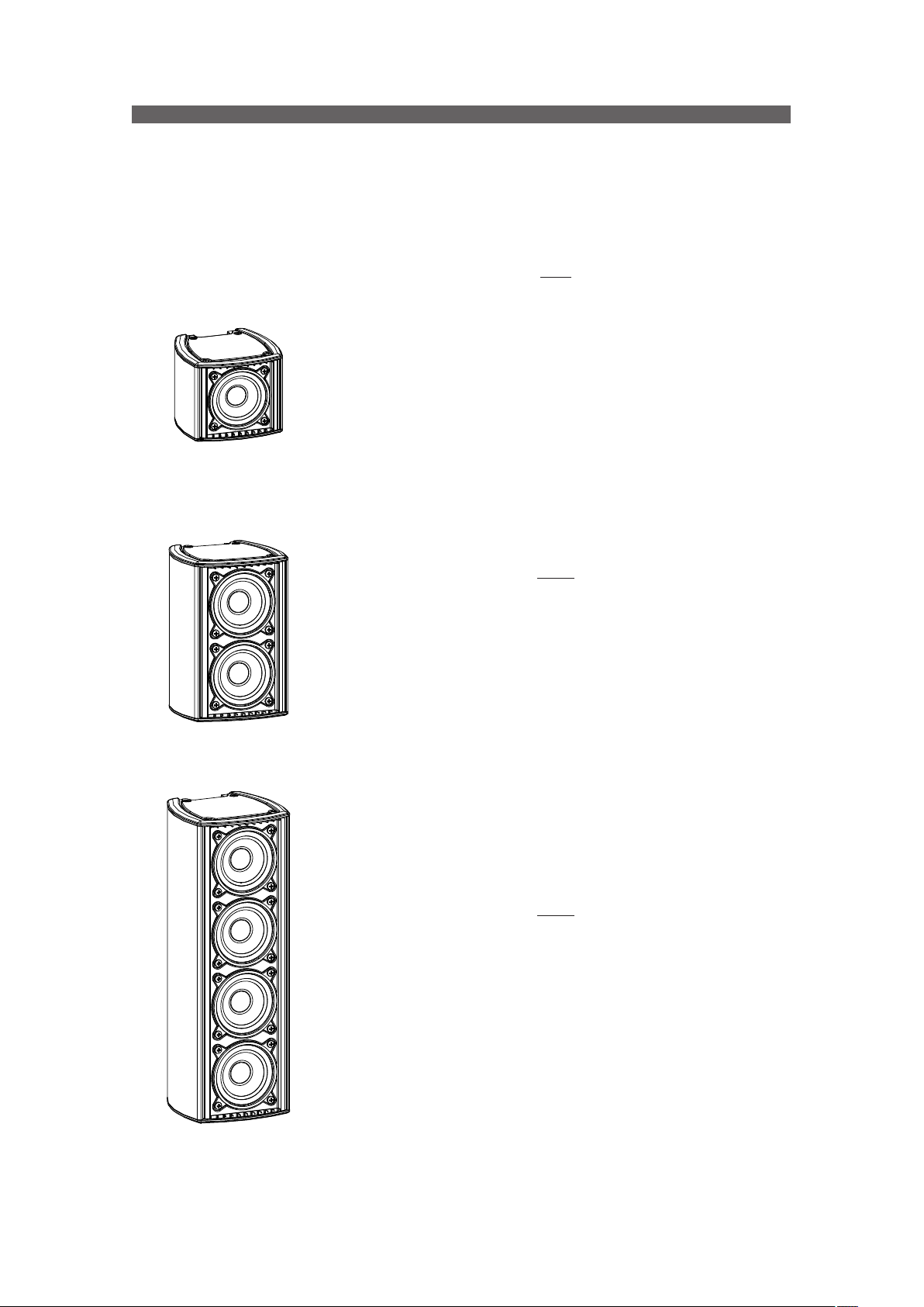
Q-3-T
Q-3-T
– Passive system
– Aluminum enclosure
– 1 x 3”, 3P full-range speaker
– Dispersion HxV: 120º x 120º
– SPL peak: 106 dB
– Multi-tap 100 / 70V transformer included
– Low and high impedance operation
– Available in all RAL colors
The Q-3-T is a highly compact and discrete system ideal for short distances,
for creatin g ambi ence, and for f rontf ill and under-bal cony sou nd
reinforcement. Like the other systems in the series, the Q-3-T has two
operating modes (voice and music) that guarantee outstanding speech
intelligibility and excellent music reproduction in any acoustic environment.
The aluminum enclosure and the IP-66 kit make this a highly reliable and
durable choice.
Q-23-T
– Passive system
– Aluminum enclosure
– 2 x 3”, 3P16 full-range speaker
– Dispersion HxV: 120º x 70º / 90º
– SPL peak: 112 dB
– Multi-tap 100 / 70V transformer included
– Low- and high-impedance operation
– Available in all RAL colors
Q-23-T
Q-43-T
The Q-23-T is a highly compact and discrete system ideal for short
distances, for creating ambience, and for f rontfill and under-balcony sound
reinforcement. The vertical dispersion can be varied by means of the systemintegrated filter (70º/90º) making it possible to control the system’s dispersion
lobe in the vertical plane reducing reflections and improving intelligibility in
spaces such as cultural centers, museums, conference rooms…all while
delivering superb music reproduction.
The aluminum enclosure and the IP-66 kit make this a highly reliable and
durable choice.
Q-43-T
– Passive system
– Aluminum enclosure
– 4 x 3”, 3P16 full-range speaker
– Dispersion H x V: 120º x 30 º / 45º
– SPL peak: 118 dB
– Multi-tap 100 / 70V transformer included
– Low and high impedance operation
– Available in all RAL colors
This system is designed for small- and mid-sized venues. The vertical
dispersion can be varied by means of the system-integrated f ilter (30º/45º)
making it possible to control the system’s dispersion lobe in the vertical plane
reducing reflections and improving intelligibility in spaces such as cultural
centers, museums, conference rooms…all while delivering superb music
reproduction.
The aluminum structure and the IP-66 kit make it a highly reliable and
resistant choice.
Manual del Usuario / Quantum series / User’s Manual
7
Page 8
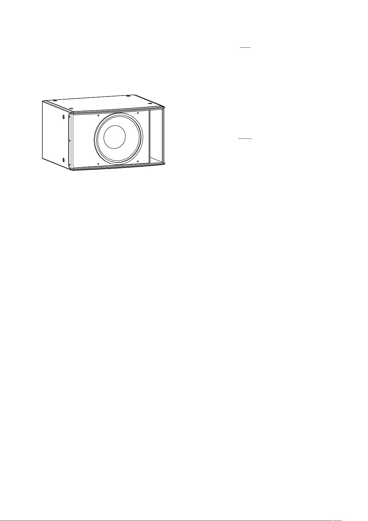
Q-10
– Ultra compact passive subwoofer system
– Birch plywood enclosure
– 1 x 10”, 10MG Loudspeaker
– Frequency range 40 Hz – 200 Hz
This ultra compact, low-profile subwoofer is ideal for
small and medium-sized installations. Low frequency
clarity and reproduction make this an unbeatable system
for delivering outstanding music reproduction. The
perfect match for the Quantum Series tops.
Q-10A
– Ultra compact powered subwoofer system
– Birch plywood enclosure
– 1 x 10”, 10MG Loudspeaker
– Frequency range 40 Hz – 200 Hz
– 500 W peak Class D amplif ier
Q-10 / Q-10A
This powered, ultra compact, low-profile subwoofer is
ideal for small- and medium-sized installations. Low
f re quency cla rity and reprodu ction make thi s an
unbeatable system for delivering outstanding music
reproduction. The perfect match for the Quantum Series tops.
The system is equipped with a class D switched-mode
amplifier, with two signal inputs, variable low-pass f ilter,
an d EQ adjust ment ( deep/lou d) w ith DASco ntrol
technology.
8
Manual del Usuario / Quantum series / User’s Manual
Page 9
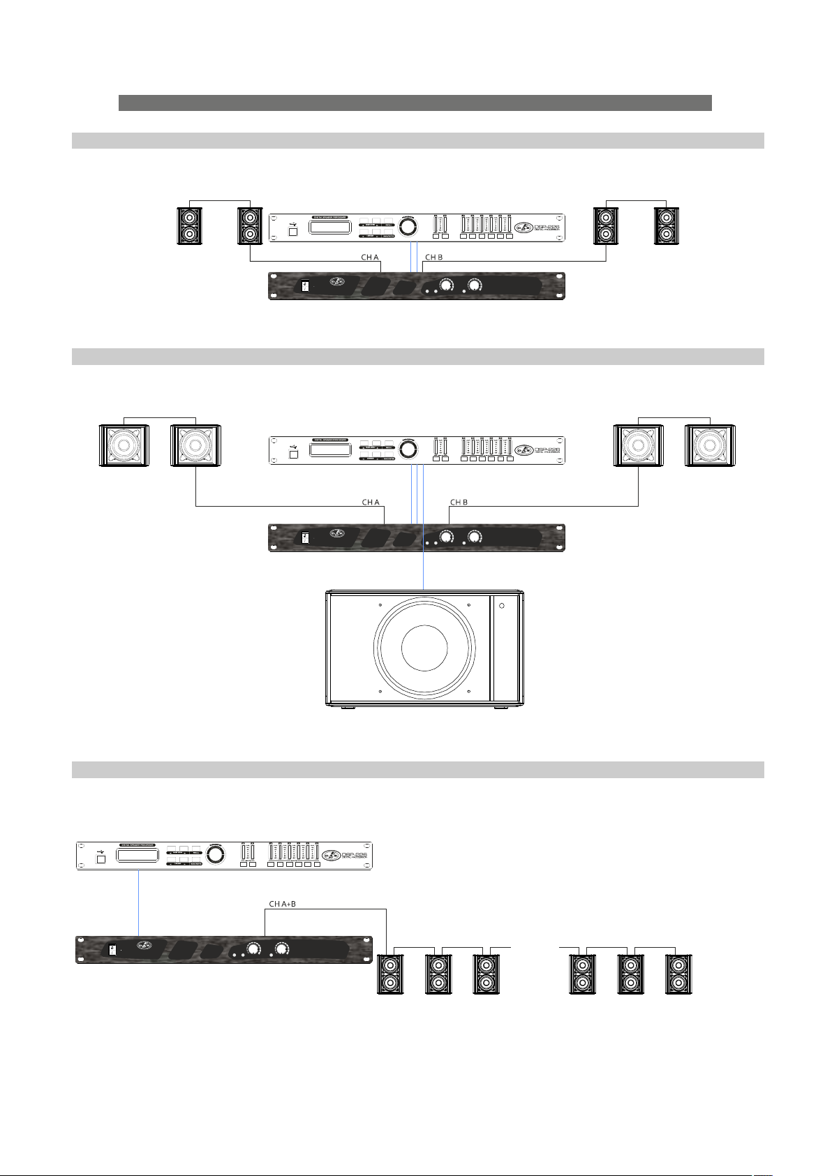
CONFIGURATIONS
Quantum Q-3-T / Q-23-T
All Amplifier Channels in Stereo Mode for low impedance operation
Select 8 ohm position
iA-402
iA-402
INSTAL LAT IO N P OW ER AM PL IF IE R
Quantum Q-3-T + Q-10A
All Amplif ier Channels in Stereo Mode for low impedance operation
Select 8 ohm position
iA-402
iA-402
INSTAL LAT IO N P OW ER AM PL IF IE R
LEVEL A LEVEL B
SIGNA L / CL IPONSIGNA L / CL IP
LEVEL A LEVEL B
SIGNA L / CL IPONSIGNA L / CL IP
Quantum Q-23-T
All Amplif ier Channels in Bridge Mode for high impedance operation
Max power available 400W per channel (20 x Q-23-T at 20W)
iA-402
iA-402
INSTAL LAT IO N P OW ER AM PL IF IE R
LEVEL A LEVEL B
SIGNA L / CL IPONSIGNA L / CL IP
Manual del Usuario / Quantum series / User’s Manual
.......
Select transformer tap position 10W/20W/30W
9
Page 10

CONFIGURATIONS (cont'd)
Quantum Q-43-T + Q-10
All Amplif ier Channels in Stereo Mode for low impedance operation
Select 4 ohm position
iA-1002
iA-1002
INSTAL LAT IO N P OW ER AM PL IF IE R
iA-1002
iA-1002
INSTAL LAT IO N P OW ER AM PL IF IE R
LEVEL A LEVEL B
SIGNA L / CL IPONSIGNA L / CL IP
LEVEL A LEVEL B
SIGNA L / CL IPONSIGNA L / CL IP
Quantum Q-43-T
All Amplif ier Channels in Stereo Mode for low impedance operation
iA-404
iA-404
INSTAL LAT IO N P OW ER AM PL IF IE R
Select 4 ohm position
Quantum Q-3-T + Q-10
All Amplif ier Channels in Stereo Mode for low impedance operation
Select 8 ohm position
iA-404
iA-404
INSTAL LAT IO N P OW ER AM PL IF IE R
LEVEL A LEVEL B LEVEL C LEVE L D
SIGNA L / CL IPONSIGNA L / CL IP S IG NA L / CL IP S IG NA L / CL IP
LEVEL A LEVEL B LEVEL C LEVE L D
SIGNA L / CL IPONSIGNA L / CL IP S IG NA L / CL IP S IG NA L / CL IP
10
Manual del Usuario / Quantum series / User’s Manual
Page 11

CONFIGURATIONS (cont'd)
Quantum Q-43-T + Q-10
All Amplif ier Channels in Stereo Mode for low impedance operation
Select 4 ohm position
iA-404
iA-404
INSTAL LAT IO N P OW ER AM PL IF IE R
Quantum Q-3-T + Q-23-T
A&B Channels in Bridge Mode for high impedance operation
C&D Channels in Stereo Mode for low impedance operation
Max power available 200W at high impedance channel (10 x Q-3-T at 20W)
LEVEL A LEVEL B LEVEL C LEVE L D
SIGNA L / CL IPONSIGNA L / CL IP S IG NA L / CL IP S IG NA L / CL IP
iA-404
.......
Select transformer tap position 10W/20W/30W
Quantum Q-43-T + Q-10
All Amplif ier Channels in Stereo Mode for low impedance operation
iA-1004
iA-1004
INSTAL LAT IO N P OW ER AM PL IF IE R
Select 4 ohm position
iA-404
INSTAL LAT IO N P OW ER AM PL IF IE R
LEVEL A LEVEL B LEVEL C LEVE L D
SIGNA L / CL IPONSIGNA L / CL IP S IG NA L / CL IP S IG NA L / CL IP
CH DCH C
LEVEL A LEVEL B LEVEL C LEVE L D
SIGNA L / CL IPONSIGNA L / CL IP S IG NA L / CL IP S IG NA L / CL IP
Select 8 ohm position
Manual del Usuario / Quantum series / User’s Manual
11
Page 12

SPECIFICATIONS
Model
RMS Power Handling
Peak Power Handling
Frequency Range (-10 dB)
On-axis Sensitivity 1 W / 1 m
Rated Peak SPL at 1 m
Horizontal Coverage (-6 dB)
Vertical Coverage (-6dB)
Nominal Impedance
Transformer Taps 100V
Transformer Taps 70V
Connectors
IP Rating
Transducers / Replacement parts
Enclosure Material
Finish
Color
Dimensions (H x W x D) [mm] 105 x 126 x 188 x 126 x 354 x 126 x 300 x 500 x
Dimensions (H x W x D) [in] 4.1 x 5 x 7.4 x 5 x 13.9 x 5 x 11.8 x 19.7 x
Weight [kg]
Weight [lb]
Accessories
Model
Nominal Amplifier Power
Nominal Amplifier Power
Input type
Frequency Range (-10 dB)
Sensitivity
Rated Maximum Peak at 1m
AC Power Requirements 1/3 Power (Pink
Noise)
Input Impedance
Connectors
Transducers/Replacement Parts
Enclosure Material
Finish
Color
Dimensions (H x W x D) [mm] 300 x 500 x
Dimensions (H x W x D) [in] 11.8 x 19.7 x
Weight [kg]
Weight [lb]
Accessories
Q-3-T
20 W
80 W
106 dB
120º
120º
8 ohm s
7.5 W - 15 W - 20 W
3.5 W - 7.5 W - 10 W
2-way Phoenix 2.54 mm
IP66
1x 3P / 3P
Aluminum
Paint
Black,White
125
4.9
1.6
3.52
AXW-4
AXW-5
JP-Q
KIT-IP-Q KIT-IP-Q KIT-IP-Q
Q-10A
250 W Continuous
500 W Peak
Balanced Differential Line
40Hz - 200Hz
Line: 1.92V (+8dBu)
121 dB
115V, 2.8A, 50 Hz / 60 Hz
230V, 1.4A, 50 Hz / 60 Hz
20 kohm s
Audio INPUT: 2x Female XLR
10MG / GM-10MG
Birch Plywood
Paint
Black,White
415
16.3
17
37.4
ANL-2
Q-23-T
40 W
160 W
150 Hz - 20 kHz150 Hz - 20 kHz
90 dB SPL87 dB SPL
112 dB
120º
Switchable: 90º -70º
8 ohm s
10 W - 20 W - 30 W
5 W - 10 W - 15 W
2-way Phoenix 2.54 mm
IP66
2x 3P16 / 3P16
Aluminum
Paint
Black,White
125
4.9
2.8
AXW-4 AXW-4
AXW-5 AXW-5
JP-Q
AXS-Q
Q-43-T
80 W
320 W
150 Hz - 20 kHz
93 dB SPL
118 dB
120º
Switchable: 45º -30º
4 ohm s
15 W - 30 W - 50 W
7.5 W - 15 W - 25 W
2-way Phoenix 2.54 mm
IP66
4x 3P16 / 3P16
Aluminum
Paint
Black,White
5.3
11.666.16
JP-Q
125
4.9
Q-10
250 W
1000 W
40 Hz - 200 Hz
94 dB SPL
121 dB
-
-
8 ohm s
-
-
2 x NL4 Speakon
1x 10MG / GM-10MG
Birch Plywood
Paint
Black,White
415
16.3
16
35.2
ANL-2
DAS Audio Group, S.L. continuously strives to enhance its products through investigation and development.
All specifications are subject to change without prior notice.
12
Manual del Usuario / Quantum series / User’s Manual
Page 13

LINE DRAWINGS
ALL DIMENSIONS IN MILLIMETERS
Q-3-TQ-43-T
Q-23-TQ-10 / Q-10A
500
300
413
Manual del Usuario / Quantum series / User’s Manual
13
Page 14

INSTALLATION & ACCESSORIES
Connectors
The Quantum series models of DAS have been designed for an easy connection.
The Q-3-T, Q-23-T and Q-43-T models offer connectors with screws to be easy fixed and to use in the most
installations.
The polarity of the contacts, as well as other important indications for their correct connection, are
indicated on the labels (see below).
Connector detail
of the device with
the indications
of the polarity.
14
Manual del Usuario / Quantum series / User’s Manual
Connector included in the
device for easy connection.
Pay attention to the polarity
indicated on the label when
screwing the connection cable.
Page 15

Page 16

The Q-10 model is provided of a pair connectors NL4 in parallel, to ease the link of devices.
The polarity of the contacts, as well as other important indications for their correct connection, are
indicated on the labels (see below).
The Q-10A model is a self powered subwoofer. Refer to the label:
1) MASTER VOLUMEN AND DSP CONTROL:
Use the encoder (1) to select the desired output
volume and push/hold it to access to the different
DSP and cabinet settings.
2) MAIN SCREEN:
In the main screen all selected settings are
shown. Besides this, there are two input level
indicators on the left, one output level indicator on
the right and the center area is reserved to display
messages as Input Clip or Limit.
3) INPUT CONNECTORS:
1/4” Jack+XLR combined socket-type input
signal connectors. This is a balanced connector
just like the OUTPUT connectors with the following
pin assignments:
1 or S =GND (ground).
2 or T =(+) Non inverted input.
3 or R =(-) Inverted input.
4) OUTPUT CONNECTORS:
XL R - type o u t put sig n a l conn e c tors f o r
connecting several units together and sending
them all the same signal.
5) POWER ON:
Mains switch.
6) AC INPUT:
IEC type mains connector which incorporates a
fuse holder. Note: If the fuse is blown, replace the
fuse with another of the same type and size.
Use this equipment with an appropriate mains
cord for your country.
2
1
4
3
5
4
3
6
16
Manual del Usuario / Quantum series / User’s Manual
Page 17

DISPLAY (only Q-10A)
By default the state of the screen is the following:
By scrolling down the encoder more options appear:
MAIN MENU
Delay: 0.0m
OPTIONS: off
BACK
Once the input source has been connected to the
amplifier´s cabinet, the user has to check the gain
structure of the system.
Adjust level output from your processor and/or mixing
console in order to prevent INPUT CLIP (left signal meter),
as shown below in the channel 1:
Peak
measurers
Exceeding the limits
may cause damage
in the system!!
After having set the input volume values under the
maximum level, user has to adjust output volume with
the master control. The level is shown in the right meter in
the screen. As with the inputs be careful not to exceed the
limit (LIMIT shown):
After these two volume adjustments the screen will
show something like this (when having the input sources
ON):
MAIN MENU:
As stated previously by pushing the encoder the user
can access the following options in the MENU:
loud 125Hz
1 2
C
0 dB
loud 125Hz
1 2
0 dB
LIMIT
loud 125Hz
1 2
0 dB
loud 125Hz
1 2
0 dB
0.0m
INPUT
CLIP
0.0m
0.0m
0.0m
O
RMS
measurer
O
L
Exceeding the limits
may cause damage
in the system!!
O
O
PRESETS:
Two factory settings (loud and deep) depending on
the type of music/use has been conf igured by default:
0 dB
0.0m
loud 125Hz
1 2
loud preset
With the encoder go to Preset Sub-menu and press
the knob to access the different options:
MAIN MENU
BACK
PRESET: loud
LPF: 125Hz
MAIN MENU
BACK
PRESET: loud >
LPF: Off
MAIN MENU
BACK
PRESET: <deep
LPF: 125Hz
LPF (Low Pass Filter):
There are 3 different options:
MAIN MENU
BACK
PRESET: loud
LPF:<125Hz>
MAIN MENU
BACK
PRESET: loud
LPF:<90Hz>
O
MAIN MENU
BACK
PRESET: loud
LPF: 125Hz
Note: to enter and select and option always push the encoder. For going back in the menu, the user has to select Back in
the screen and press the encoder or just pushing the encoder.
After 30 seconds without touching the button, the unit will return to the main screen automatically.
Manual del Usuario / Quantum series / User’s Manual
MAIN MENU
BACK
PRESET: loud
LPF:<170Hz
17
Page 18

OPTIONS:
In this sub-menu the user can configure all the non-audio related options. Remember that in order to access each
parameter it is necessary to push the encoder:
OPTIONS MENU
BACK
BRIGHT: 0
CONTRAST: 0
OPTIONS MENU OPTIONS MENU OPTIONS MENU
BACK BACK BACK
BRIGHT: 0 BRIGHT: 0 BRIGHT: 0
CONTRAST: 0
OPTIONS MENU
DIMMING: on
LOGO: off
MENU LOCK: off
DIMMING: When active the screen lowers its luminosity after a few seconds
OPTIONS MENU
DIMMING: on
LOGO: off
MENU LOCK: off
A. User can LOCK the Display and Master Volume Control by enabling this option MENU LOCK: ON
B. User can LOCK the Display and the encoder WITH PASSWORD by enabling this option MENU LOCK: pw292
In case A, to unlock just press the encoder: In case B, to unlock PUSH encoder and enter the 3 digit password (292):
OPTIONS MENU OPTIONS MENU
BACK BACK
BRIGHT: 0 BRIGHT: +10
CONTRAST: 0 CONTRAST: 0
CONTRAST: -10 CONTRAST: +10
OPTIONS MENU
DIMMING: <on
LOGO: off
MENU LOCK: off
OPTIONS MENU
DIMMING: on
LOGO: off LOGO: off LOGO: off
MENU LOCK: off>
OPTIONS MENU
DIMMING: off>
LOGO: off
MENU LOCK: off
OPTIONS MENU OPTIONS MENU
DIMMING: on DIMMING: on
MENU LOCK: <on> MENU LOCK:<pw292
LOCKED
0 dB
PUSH TO UNLOCK
+ 0dB
loud 125Hz
1 2
OPTIONS MENU
DLY UNITS: m
RESET DEVICE
INFORMATION
OPTIONS MENU
DLY UNITS: m
RESET DEVICE
INFORMATION
OPTIONS MENU
RESET DEVICE
INFORMATION
BACK
0.0m
UNLOCKED
0 dB
+ 0dB
0.0m
loud 125Hz
O
1 2
OPTIONS MENU OPTIONS MENU
DLY UNITS: m> DLY UNITS:<ft
RESET DEVICE RESET DEVICE
INFORMATION INFORMATION
RESET DEVICE
Are you sure?
NO YES
This option resets the device to the following values:
O
Password: 0 0 0
0 dB
loud 125Hz
1 2
0.0m
Preset: loud
LPF: AlTop
Dimming: on
LOGO: on
MENU LOCK: off
O
QUANTUM
Q10A
FW v0.10 2602
18
Manual del Usuario / Quantum series / User’s Manual
Page 19

Accessories: JP-Q and ANL-2
To perform any operations related to flying the system, read the present document first, and act on the
warnings and advice given.
The goal is to allow the user to become familiar with the mechanical elements required to fly the acoustic
system, as well as the safety measures to be taken during set-up and teardown.
Only experienced installers with adequate knowledge of the equipment and local safety regulations
should fly speaker boxes.
It is the user's responsibility to ensure that the systems to be flown (including flying accessories) comply
with state and local regulations.
The working load limits in this manual are the results of tests by independent laboratories. It is the user's
responsibility to stay within safe limits. It is the user's responsibility to follow and comply with safety factors,
resistance values, periodical supervisions and warnings given in this manual.
Product improvement by means of research and development is on going at DAS Specifications are
subject to change without notice.
It is common practice to apply 5:1 safety factors for enclosures and static elements.
For slings and elements exposed to material fatigue due to friction and load variation the following ratios
must be met; 5:1 for steel cable slings, 4:1 for steel chain slings and 7:1 polyester slings.
Thus, an element with a breaking load limit of 1000 kg may be statically loaded with 200 kg (5:1 safety
factor) and dynamically loaded with 142 Kg (7:1 safety factor).
The load capacity, of each lift motor, should correspond to a safety factor of 10:1.
When flying a system, the working load must be lower than the resistance of each individual flying point
in the enclosure, as well as each box.
Hanging hardware should be regularly inspected and suspect units replaced if in doubt.
This is important to avoid injury and absolutely no risks should be taken in this respect. It is highly
recommended that you implement an inspection and maintenance program on flying elements, including
reports to be f illed out by the personnel that will carry out the inspections.
Local regulations may exist that, in case of accident, may require you to present evidence of inspection
reports and corrective actions after defects were found.
Absolutely no risks should be taken with regards to public safety.
When flying enclosures from ceiling support structures, extreme care should be taken to assure the load
bearing capabilities of the structures so that the installation is absolutely safe.
Do not fly enclosures f rom unsafe structures.
Consult a certified professional if needed.
All flying accessories that are not supplied by DAS Audio are the user's responsibility. Use at your own risk.
% Working
Load
JP-Q
0 Degrees
100% 65% 30% 25%
30 Degrees 45 Degrees More than
ANL-2
45 Degrees
Manual del Usuario / Quantum series / User’s Manual
19
Page 20

The JP-Q accessory allows the installation of devices of the Quantum series suspended by means of rings.
Note: Make sure the slings
have the robustness and
appropriate length.
Also, the JP-Q accessory allows the union of several boxes of the Quantum series (example Q-43-T), forming
columns, which can then be suspended by means of rings.
Note: The upper Q-43-T
is mounted inverted
to improve coverage.
Note: Make sure the slings
have the robustness and
appropriate length.
20
We will add another JP-Q
in the upper part to obtain
the desired inclination.
Manual del Usuario / Quantum series / User’s Manual
Page 21

To hang the units, Q-10 or Q-10A, the ANL-2 accessory is needed. To install this accessory, the Allen-head
screws must be removed and replaced by M10 eyebolts on one side of the enclosure. Each rigging point has a
200 kg (440 lb) working load limit.
Then choose the slings or chains of a required load resistance and length, bearing in mind that the length
difference between the front and back slings or chains will determine the vertical orientation. Alternatively,
the back bottom eyebolt points can be used to provide vertical orientation.
The ANL-2 set is an optional set of four eyebolts and four carabiners. (Dimensions are in milimetres).
Each ANL-2 eyebolt has a rated working load of 200 kg. (440 lb). Each ANL-2 carabiner has a working load of
330 kg (726 lb). If using other hardware, make sure it is rated to handle the required load.
When using eyebolts it is important to bear in mind that the rated working load is only true for a load
applied in the plane of the eye, and is significantly reduced for other angles. The drawing above illustrates the
concept.
The table shows the variation of the working load as a function of the load angle. In the case of the ANL-2
eyebolt, this means that the 200 kg working load becomes 60 kg at 45 degrees. Do not use eyebolt flying if the
load angle is higher than 45 degrees.
Note: As always, when we handle heavy loads, we should wear appropriate clothing and protective
elements such as gloves, safety shoes, etc.
Accessory: AXW-5
The AXW-5 accessory is a wall mount bracket that allows the easy installation of Quantum series units
(fixed inclination of -15º).
AXW-5
1.- First, we will screw
the AXW-5 plate to
the back of the box.
Note: In the case of using
the AXW-5 with a Q-3-T
with an KIT-IP-Q accessory
installed, rotate and mount
the plate as indicated in the
figure, for a correct attachment.
Manual del Usuario / Quantum series / User’s Manual
21
Page 22

40 mm
2.- Make two holes
in the wall 40 mm apart and
screw the body of the AXW-5
that we will then join to the
back of the unit.
3.- Attach the loudspeaker unit and
manually tighten the screw to lock the unit.
Accessory: AXW-4
Note: The AXW-5 gives an fixed inclination of -15º to the unit.
The AXW-4 accessory is a wall mount bracket that permits variable angle inclination of a Quantum series unit.
AXW-4
48 mm
1.- First, make four holes
in the wall separated according
to the figure, we will place the
wall plugs and partially
screw the 4 screws.
42 mm
50.5 mm
22
Manual del Usuario / Quantum series / User’s Manual
Page 23

2.- Screw the AXW-4
to the back of the box.
Vertical assembly
Horizontal assembly
DETAIL
Note: Screw the AXW-4
to the back of a Q-3-T,
as shown in the figure.
3.- Match the holes with the screws and tighten them firmly.
Unit attached to the wall.
Manual del Usuario / Quantum series / User’s Manual
23
Page 24

4.- Finally, select the angles for the box, first the vertical
And then, the horizontal:
Fix the angle by tightening the screw (1a)
and its opposite
Accessory: KIT-IP-Q
The KIT-IP-Q accessory allows a Quantum series unit to acquire a degree of protection IP-66 according to IEC-
60529. In the attached figures the steps for their assembly are shown:
Fix the angle by tightening the
screws (1b and 2b)
1 2 3
(-) INPU T (+)
4 5 6
1.- Loosen the nut of the cable gland to insert the cable.
2.- Insert the cable through the cable gland.
3.- Remove the connector from the cabinet and screw the cable attach paying attention to the polarity
indicated on the cabinet label.
4.- Connect the cable to the cabinet using the connector and fix it with its screws.
5.- Position the cover according to the label and fix it to the cabinet with the supplied screws.
6.- Pull the cable so that it is not too long and secure the rubber seal to the cable before tightening the
nut of the cable gland.
24
Manual del Usuario / Quantum series / User’s Manual
Page 25

Accessory: AXS-Q
The AXS-Q accessory allows to place a Q-23-T on a flat surface, giving it an angle of -15º, 0º, 20º or 40º, as
shown below.
AXS-Q
(4x 4.2x9.5 DIN 7981 included)
1.- First, place
the pieces the upper
and lower ends
2.- Screw the pieces
to the unit by means of
the supplied screws
3.- Now we can place
the unit on the flat surface,
with the desired angle
Q-23-T with 0º of inclination Q-23-T with 40º of inclination
Manual del Usuario / Quantum series / User’s Manual
25
Page 26

In summary, with this accessory a Q-23-T can have the following angles:
26
Manual del Usuario / Quantum series / User’s Manual
Page 27

ANNEX : Table for cable selection
This table shows the power loss in % and dB, for different cable lengths and sections shown. It is
recommended that the losses do not exceed 30% in any case (around 3dB). Although it is recommended
minimizing losses, the maximum acceptable losses are usually around 15% (approximately 1.4dB).
Manual del Usuario / Quantum series / User’s Manual
27
Page 28

www.dasaudio.com
UM_Q_01_EN
DAS Audio Group, S.L.
C/. Islas Baleares, 24
46988 Fuente del Jarro
Valencia, SPAIN
Tel. +34 96 134 0860
DAS Audio of America, INC.
6900 NW 52th Street
Miami, FL. 33166 - U.S.A.
TOLL FREE: 1 888 DAS 4 USA
DAS Audio Asia PTE. LTD.
3 Temasek Avenue, Centennial
Tower #34-36
Singapore 039190
Tel. +65 6549 7760
DAS do Brasil LTDA.
Rua Dos Andradas, 382 SL
Santa Efigênia, São Paulo
Brasil. CEP: 01208-000
Tel. +551133330764
 Loading...