

Page 1
User's Manual
line array
EVENT-208A / EVENT-210A / EVENT-M210A / EVENT-218A
Antes de utilizar el equipo, lea la sección
“Precauciones de seguridad” de este manual.
Conserve este manual para futuras consultas.
Before operating the device, please read the
“Safety precautions” section of this manual.
Retain this manual for future reference.
Page 2

CONTENTS
SAFETY PRECAUTIONS
WARRANTY
DECLARATION OF CONFORMITY
INTRODUCTION
CONFIGURATIONS
8 EVENT-208A + 4 EVENT-218A
12 EVENT-208A + 6 EVENT-218A
16 EVENT-210A + 8 EVENT-218A
24 EVENT-210A + 12 EVENT-218A
SPECIFICATIONS
LINE DRAWINGS
AMPLIFIER
Description
ON / OFF
Overload indicator
Equalisation
Overheating
Low mains voltage
3
4
5
6
7 a 10
11
12
13 a 15
Current consumption
Troubleshooting
RIGGING SYSTEM
ANNEX
Line conections: unbalanced and balanced
16 a 17
18
Manual del Usuario / event series / User’s Manual
Page 3
Precauciones de Seguridad
line array
Cajas acústicas activas / Self-powered loudspeaker enclosures
Safety Precautions
El signo de exclamación dentro de un triángulo indica la
existencia de importantes instrucciones de operación y
mantenimiento en la documentación que acompaña al producto.
Conserve y lea todas estas instrucciones. Siga las advertencias.
ATENCIÓN: Es un producto clase A, por lo que en entornos
domésticos puede causar radio-interferencias, en cuyo caso el
usuario tendrá que tomar las medidas oportunas.
De acuerdo con EN55103-2, usar el equipo sólo en entornos E1,
E2, E3 ó E4.
No desconecte la tierra en el conector de alimentación pues es
peligroso e ilegal. Equipo de Clase I. El producto debe ser
conectado a un enchufe con toma de tierra. Sólo use este
equipo con el cable de red de alimentación adecuado para su
país.
El signo del rayo con la punta de flecha, alerta contra la
presencia de voltajes peligrosos no aislados. Para reducir el
riesgo de choque eléctrico, no retire la cubierta.
No instale el aparato cerca de ninguna fuente de calor como
radiadores, estufas u otros aparatos que produzcan calor. Debe
instalarse siempre sin bloquear la libre circulación de aire por las
aletas del radiador.
No exponga este equipo a la lluvia o humedad sin el protector
de lluvia recomendado. No exponga el equipo a salpicaduras sin
el protector de lluvia recomendado, ni coloque sobre él objetos
que contengan líquidos, tales como vasos y botellas.
Este símbolo indica que el presente producto no puede ser
tratado como residuo doméstico normal, sino que debe
entregarse en el correspondiente punto de recogida de equipos
eléctricos y electrónicos.
The exclamation point inside an equilateral triangle is intended to
alert the users to the presence of important operating and
mainten ance (servi cing) instruc tions in the li terature
accompanying the product. Heed all warnings. Follow all
instructions. Keep these instructions.
WARNING: This is a class A product. In a domestic environment
this product may cause radio interferences in which case the
user may be required to take adequate measures.
Use this product only in E1, E2, E3 or E4 environments
according to EN55103-2.
Do not remove mains connector ground, it is dangerous and
illegal. Class I device. The product must be connected to a
mains socket outlet with protective earth connection. Only use
this equipment with an appropriate mains cord for your country.
The lightning and arrowhead symbol warns about the presence
of uninsulated dangerous voltage. To reduce the risk of electric
shock, do not remove the cover.
Do not install near any heat sources such as radiators, heat
registers, stoves or other apparatus that produce heat.
The circulation of air through the heatsink must not be blocked.
Do not expose this device to rain or moisture without the rain
protector supplied. Do not place any objects containing liquids,
such as bottles or glasses, on the top of the unit. Do not splash
liquids on the unit without the rain protector supplied.
This symbol on the product indicates that this product should
not be treated as household waste. Instead it shall be handed
over to the appicable collection point for the recycling of
electrical and electronic equipment.
Equipo diseñado para funcionar entre 15ºC y 45ºC con una
humedad relativa máxima del 95%, con un rango de ±10% de la
tensión nominal de alimentación indicada en la etiqueta trasera
(según IEC 60065). Si debe sustituir el fusible preste atención al
tipo y rango.
El cableado exterior conectado al equipo requiere de su
instalación por una persona instruida o el uso de cables flexibles
ya preparados.
Si el aparato es conectado permanentemente, la instalación
eléctrica del edificio debe incorporar un interruptor multipolar con
separación de contacto de al menos 3mm en cada polo.
Para desconectar el dispositivo debe usar el enchufe.
Desconecte este aparato durante tormentas eléctricas,
terremotos o cuando no se vaya a emplear durante largos
periodos.
No emplace altavoces en proximidad a equipos sensibles a
campos magnéticos, tales como monitores de televisión o
material magnético de almacenamiento de datos.
El colgado del equipo sólo debe realizarse utilizando los herrajes
de colgado recomendados y por personal cualificado. No
cuelgue la caja de las asas y respete los valores máximos de
carga dados en el manual.
No existen partes ajustables por el usuario en el interior de este
equipo. Cualquier operación de mantenimiento o reparación
debe ser realizada por personal cualificado. Es necesario el
servicio técnico cuando el equipo se haya dañado de alguna
forma, como que haya caído líquido o algún objeto en el interior
del aparato, haya sido expuesto a lluvia o humedad, no funcione
correctamente, haya recibido un golpe o su cable de red esté
dañado.
Limpie con un paño seco. No use limpiadores con disolventes. Clean only with a dry cloth. Do not use any solvent based
Working temperature ranges from 15ºC to 45ºC with a relative
humidity of 95%, with ±10% of the rated main voltage value
indicated on the rear label (according to IEC 60065). If the fuse
needs to be replaced, please pay attention to correct type and
ratings.
The outer wiring connected to the device requires installation by
an instructed person or the use of a flexible cable already
prepared.
If the apparatus is connected permanently, the electrical system
of the building must incorporate a multipolar switch with a
separation of contact of at least 3mm in each pole.
To disconnect the device, you should use the mains plug. Unplug
this apparatus during lightning storms, earthquakes or when
unused for long periods of time.
Do not place loudspeakers in proximity to devices sensitive to
magnetic fields such as television monitors or data storage
magnetic material.
The appliance should be flown only from the rigging points and
by qualified personnel. Do not suspend the box from the handles
and respect the maximium load values given in the manual.
No user serviceable parts inside. Refer all servicing to qualified
service personnel. Servicing is required when the apparatus has
been damaged in any way, such as power-supply cord or plug is
damaged, liquid has been spilled or objects have fallen into the
apparatus, the apparatus has been exposed to rain or moisture,
does not operate normally or has been dropped.
cleaners.
Manual del Usuario / event series / User’s Manual
3
Page 4

GARANTÍA
Todos nuestros productos están garantizados por un periodo de 24
meses desde la fecha de compra.
Las garantías sólo serán válidas si son por un defecto de
fabricación y en ningún caso por un uso incorrecto del producto.
Las reparaciones en garantía pueden ser realizadas,
exclusivamente, por el fabricante o el servicio de asistencia técnica
autorizado.
Otros cargos como portes y seguros, son a cargo del comprador
en todos los casos.
Para solicitar reparación en garantía es imprescindible que el
producto no haya sido previamente manipulado e incluir una
fotocopia de la factura de compra.
WARRANTY
All our products are warrantied against any manufacturing defect
for a period of 2 years from date of purchase.
The warranty excludes damage from incorrect use of the product.
All warranty repairs must be exclusively undertaken by the factory
or any of its authorised service centers.
To claim a warranty repair, do not open or intend to repair the
product.
Return the damaged unit, at shippers risk and freight prepaid, to
the nearest service center with a copy of the purchase invoice.
4
Manual del Usuario / event series / User’s Manual
Page 5

DECLARACIÓN DE CONFORMIDAD
DECLARATION OF CONFORMITY
DAS Audio Group, S.L.
C/ Islas Baleares, 24 - 46988 - Pol. Fuente del Jarro - Valencia. España
(Spain).
Declara que la serie event:
Declares that event series:
Cumple con los objetivos esenciales de las Directivas:
Abide by essential objectives relating Directives:
l Directiva de Baja Tensión (Low Voltage Directive) 2014/35/UE
l Directiva de Compatibilidad Electromagnética (EMC) 2014/30/UE
l Directiva RoHS 2011/65/UE
l Directiva RAEE (WEEE) 2012/19/UE
Y es conforme a las siguientes Normas Armonizadas Europeas:
In accordance with Harmonized European Norms:
l EN 60065:2014.- Audio, video and similar electronic apparatus. Safety
requirements.
l EN 55032:2012.- Electromagnetic compatibility of multimedia equipment.
Emission requirements.
l EN 55103-2:2009.- Electromagnetic compatibility. Product family
standard for audio, video, audio-visual and entertainment lighting control
apparatus for professional use. Part 2:Immunity.
l EN 50581:2012.- Technical documentation for the assessment of
electrical and electronic products with respect to the restriction of
hazardous substances.
Manual del Usuario / event series / User’s Manual
5
Page 6
INTRODUCTION
For portable live sound applications, or fixed installations in almost any type of venue, the Event Line Arrays have
been designed to provide exceptional sound, steadfast reliability and value beyond comparison.
Also, the Event Line Arrays incorporate high frequency waveguides designed with the same technology as the aero
series. The Event series is composed of EVENT-208A and EVENT-210A, the monitor EVENT-M210A and the subwoofer
EVENT-218A, to provide a complete solution for all your Events.
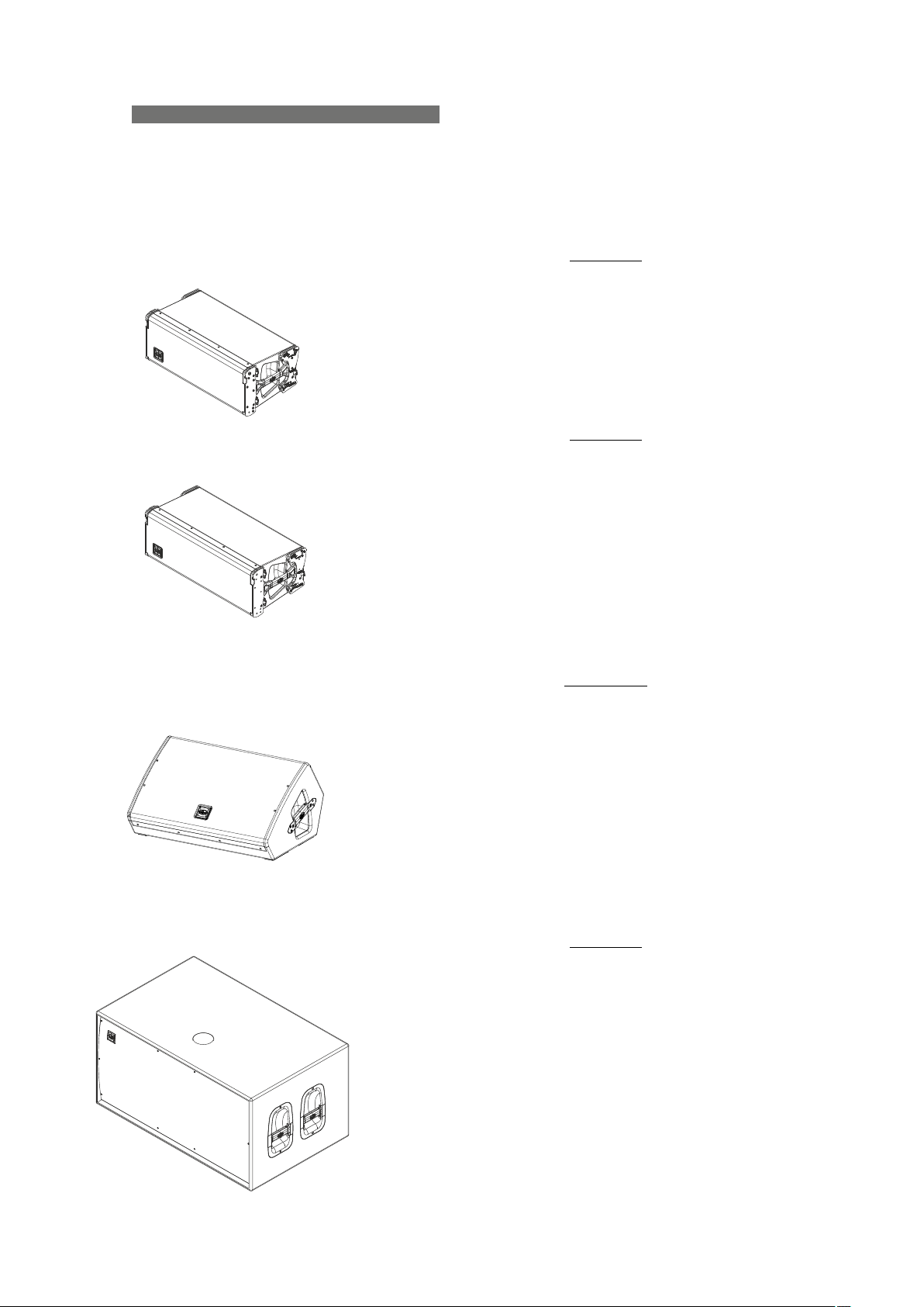
EVENT-208A
- Three-way powered system
- Two 8" mid and bass loudspeakers
- Compression driver with titanium diaphragm
- Newly developed high frequency waveguide
- Optimized rigging and stacking system
The EVENT-208A is a three-way powered system (3 channel
Class D amplifier) with an 8” for bass and another 8" for mid range,
and a compression driver, M-75, with 3" titanium diaphragm and
1.5” exit.
EVENT-210A
- Three-way powered system
- Two 10" mid and bass loudspeakers
- Compression driver with titanium diaphragm
- Newly developed high frequency waveguide
- Optimized rigging and stacking system
The EVENT-210A is three-way powered system (3 channel Class
D amplifier) with a 10” for bass and another 10" for mid range, and a
compression driver, M-75, with 3" titanium diaphragm and 1.5” exit.
Both include a three-way Class D amplifier that deliver 1200W
peak power, and a comprehensive protection package, with peak
and RMS limiters, to provide reliability and durability. With regards to
DSP, the EZ-DSPTM system simplifies switching between short and
medium throw, for accurate coverage.
EVENT-M210A
- Powered 3-way stage monitor
- Two 10" mid and bass loudspeakers
- Compression driver with titanium diaphragm
- Newly developed high frequency waveguide
- Optimized rigging and stacking system
The EVENT-M210A is three-way powered system (3 channel
Class D amplifier) with a 10” for bass and another 10" for mid range,
and a compression driver, M-60, with 1.75" titanium diaphragm and
1” exit.
Both include a three-way Class D amplifier that deliver 1200W
peak power, and a comprehensive protection package, with peak
and RMS limiters, to provide reliability and durability. With regards to
DSP, the EZ-DSPTM system simplifies switching between short and
medium throw, for accurate coverage.
EVENT-218A
- Powered subwoofer with high efficiency
- Two low frequency 18" cone loudspeakers
- Cabinet designed for horizontal stacking
- Top located pole mount socket (Ø 35mm)
The EVENT-218A is the subwoofer needed for an optimum
coupling with the Event Line Arrays. It incorporates two 18"
loudspeakers with 4" coil and high efficiency.
The EVENT-218A includes a Class D amplifier that delivers
3200W peak power, and a comprehensive protection package, with
peak and RMS limiters, to provide reliability and durability.
All cabinets have a robust birch plywood construction, finished
with ISO-flex paint for both good looks and a durable protective
coating, and a rugged protective steel grille safeguards the DAS
components. Also, the systems incorporate protectors that protect
the amplifiers from the sun and rain.
6
Manual del Usuario / event series / User’s Manual
Page 7
CONFIGURATIONS
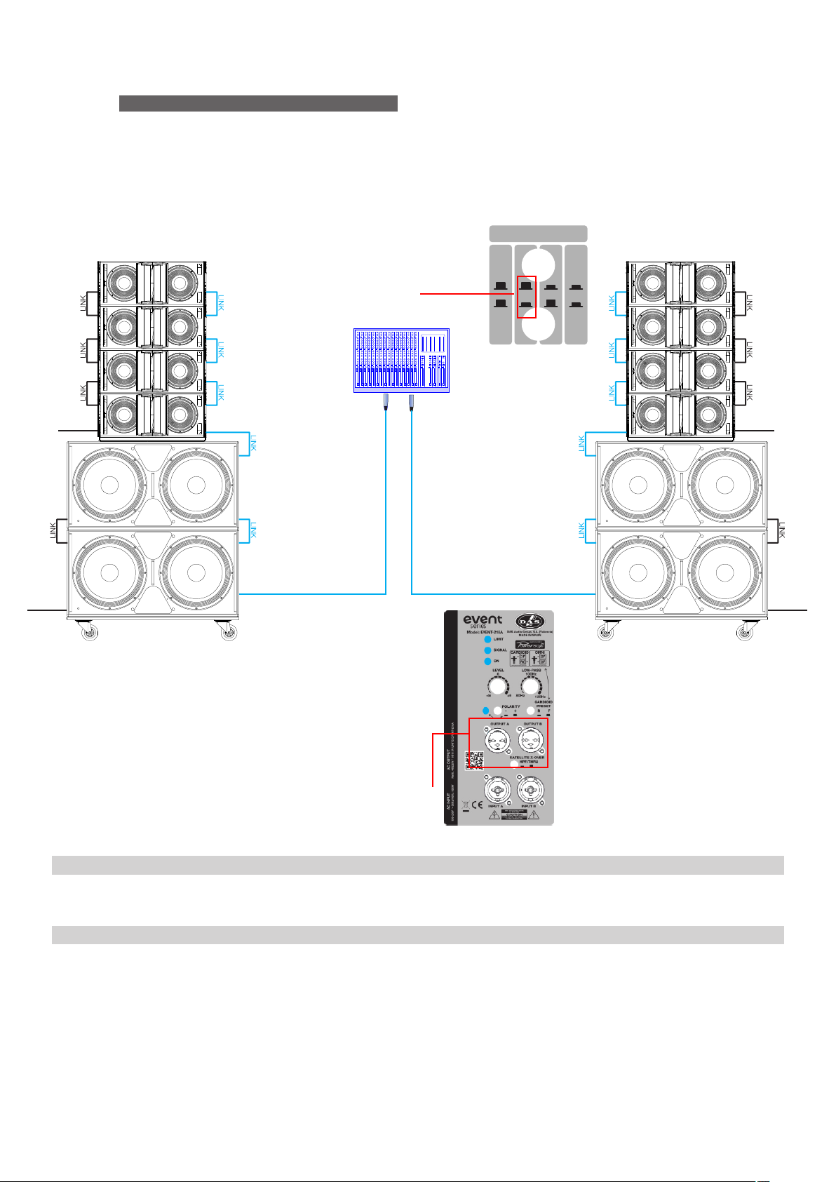
To continue, four configuration examples. You will find more on the web page: www.dasaudio.com.
8 x EVENT-208A
4 x EVENT-218A
Select the preset of 4 units
on the amplifier´s control panel
POWE R POWE R
POWE R POWE R
Small Stacked 21500W peak power system
NUMBER OF UNITS
4
L R
81 6
Use the Satellite X-over on the EVENT-218A for
the EVENT-208A cabinets (HPF knob must be pressed)
Speaker cabling
PWCONLINK-09 0.9m powerCON NA C3FCB cable
SC-1 1m X LR microphone signal balanced cable
Rigging frames
AXS-EV208 Stacking bracket for E VENT-208A (max 4 u./max 1 u. using TRD-6/TR D-2), black
PL-EV218S Wooden transport dolly for EVEN T-218A (max 3 u.), black
Manual del Usuario / event series / User’s Manual
Units
8
10
Units
2
2
7
Page 8
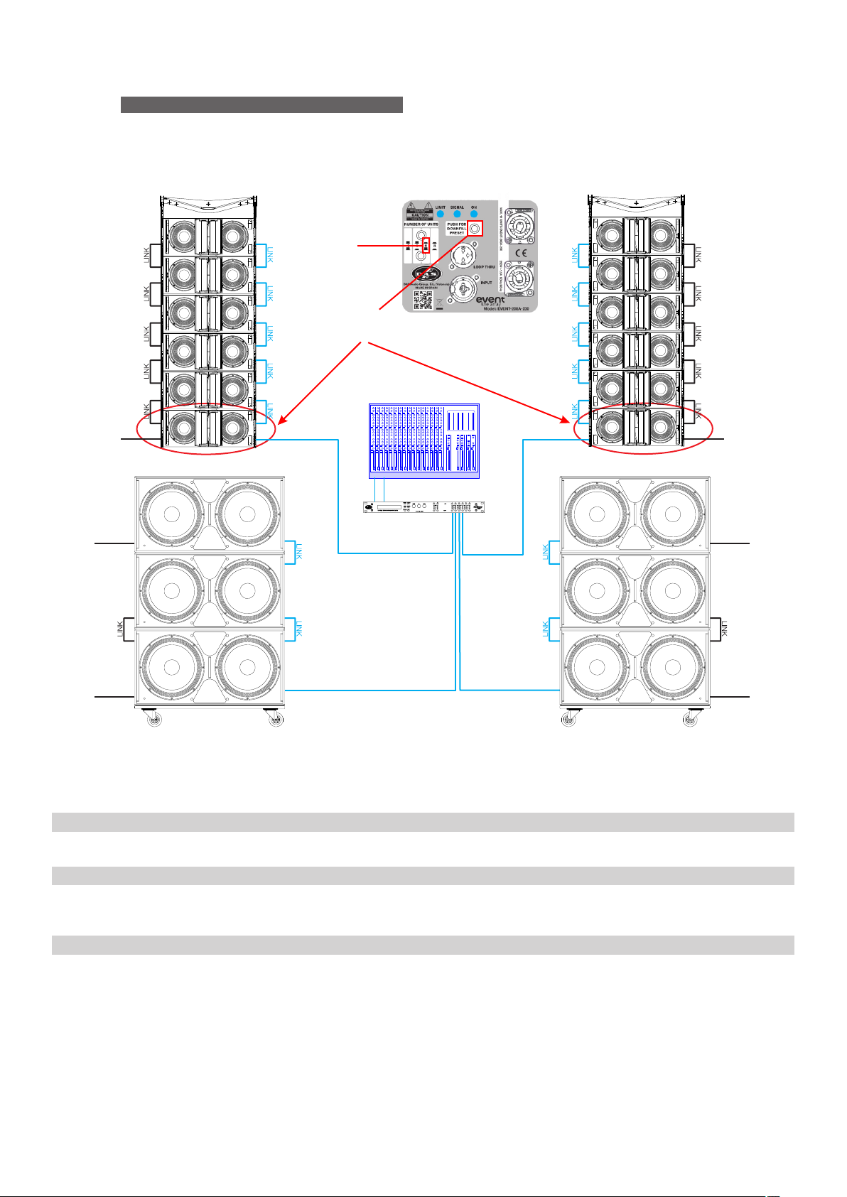
CONFIGURATIONS (cont’d)
Note: You will find more examples on the web page: www.dasaudio.com.
12 X EVENT-208A
Medium flown 32000W peak power system
6 X EVENT-218A
Select the preset of 6 units
on the amplifier´s control panel
Also, select the DOWN FILL preset
on the amplifier´s control panel
of these units
POWE R
POWE R
Processors
DSP-2060A 0.9m powerCON NA C3FCB cable
L R
SUB L SUB R
DSP-2060A
TOP RTOP L
POWE R
POWE RPOWE R
POWE R
Units
1
Speaker cabling
PWCONLINK-09 0.9m powerCON NA C3FCB cable
SC-1 1m X LR microphone signal balanced cable
Rigging frames
AX-EV208 Rigging bumper for EVE NT-208A (max 16 u.), black
PL-EV208S Steel transport dolly for EVE NT-208A (max 4 u.), black
PL-EV218S Wooden transport dolly for EVEN T-218A (max 3 u.), black
8
Units
12
14
Units
2
3
2
Manual del Usuario / event series / User’s Manual
Page 9
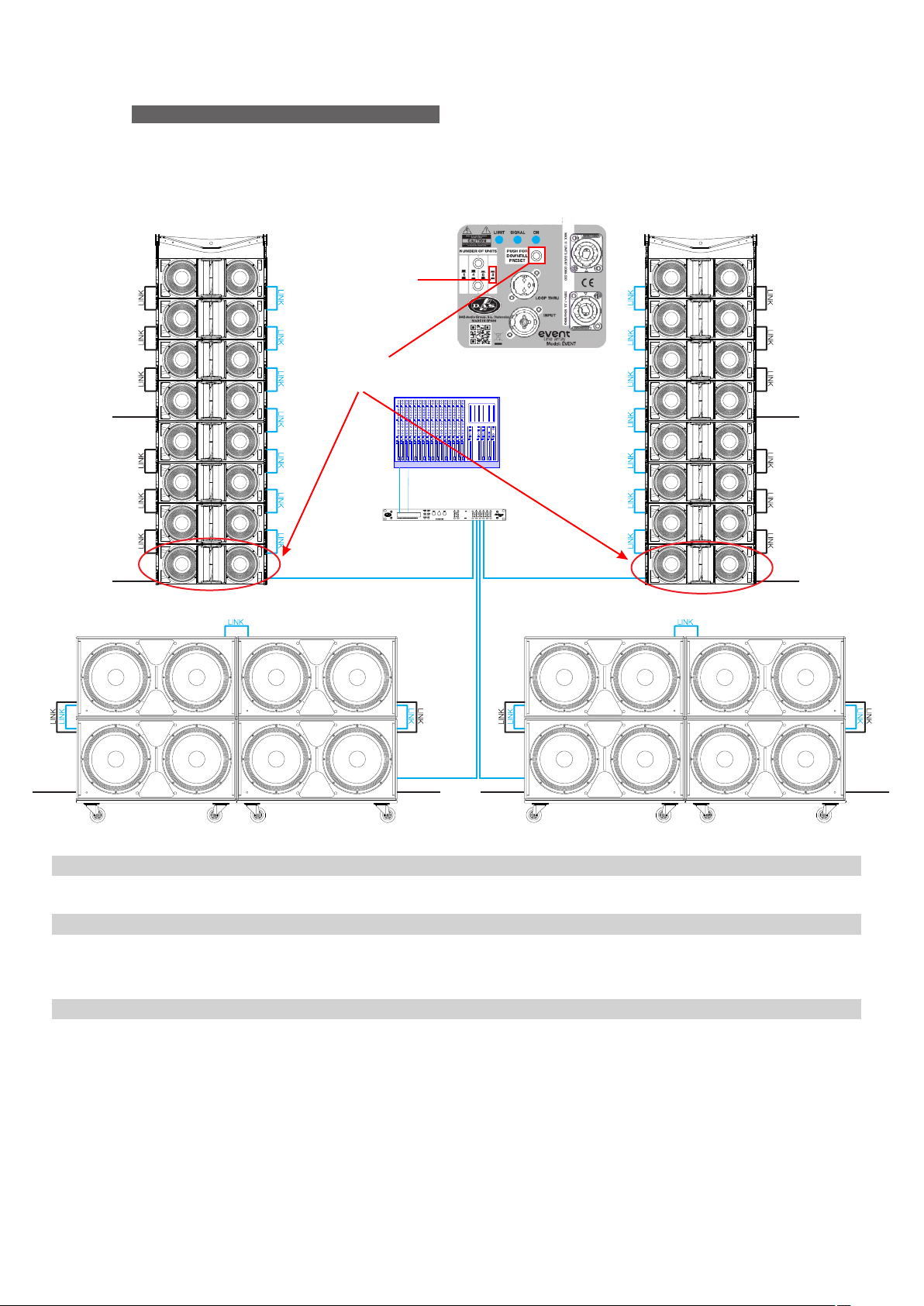
CONFIGURATIONS (cont’d)
Note: You will find more examples on the web page: www.dasaudio.com.
POWE R
POWE R
16 X EVENT-210A
8 X EVENT-218A
Also, select the DOW NFILL
preset on the amplifier´s control
Medium - large flown 42800W peak power system
Select the preset of 8 units
on the amplifier´s control panel
210A-230
panel of these units
L R
TOP L TO P R
DSP-2060A
POWE R
POWE R
Processors
DSP-2060A 0.9m powerCON NA C3FCB cable
Speaker cabling
PWCONLINK-09 0.9m powerCON NA C3FCB cable
SC-1 1m X LR microphone signal balanced cable
SC-2 2m X LR microphone signal balanced cable
Rigging frames
AX-EV210 Rigging bumper for EVE NT-210A (max 16 u.), black
PL-EV210S Steel transport dolly for EVE NT-210A (max 4 u.), black
PL-EV218S Wooden transport dolly for EVEN T-218A (max 3 u.), black
POWE R POWE R
SUB RSUB L
POWE RPOWE R
Units
1
Units
16
18
2
Units
2
4
4
Manual del Usuario / event series / User’s Manual
9
Page 10
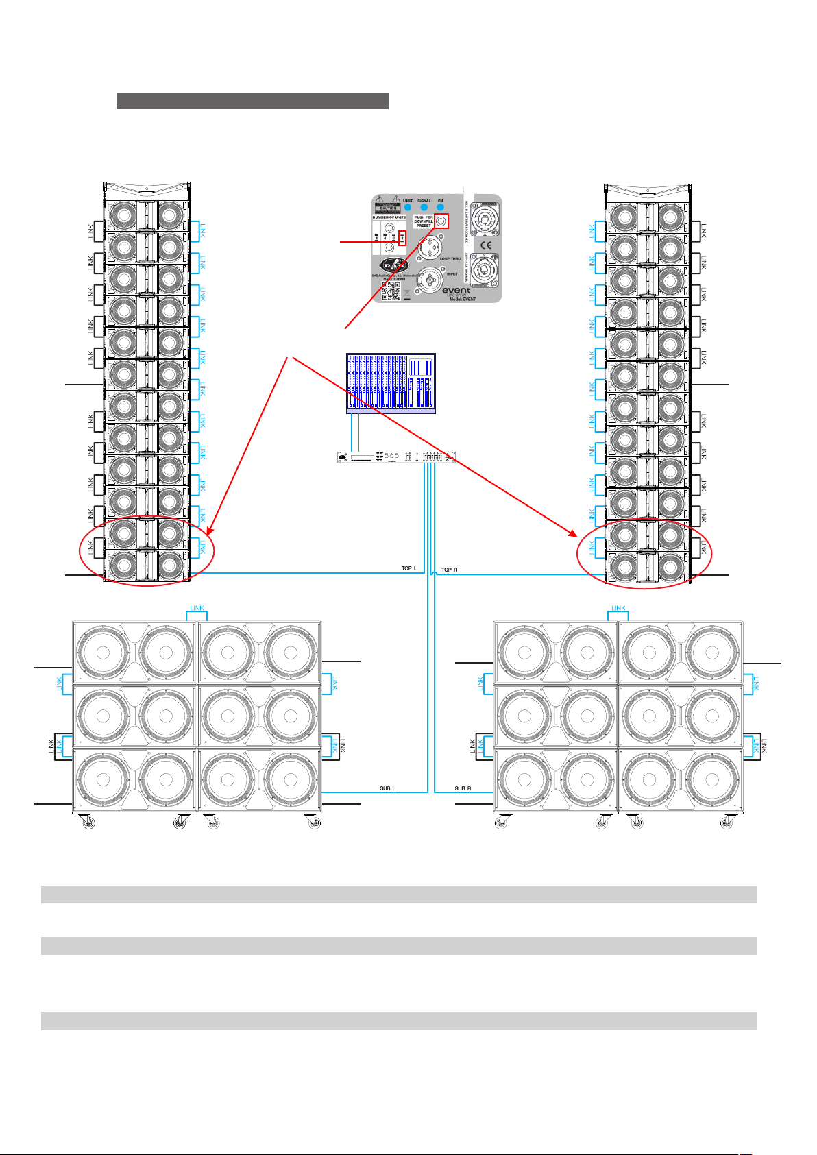
CONFIGURATIONS (cont’d)
Note: You will find more examples on the web page: www.dasaudio.com.
POWE R
24 X EVENT-210A
12 X EVENT-218A
Select the preset of 8* units
on the amplifier´s control panel
*The 8 units preset can be
used when rigging 12 units. If
the user wants to lower the
amount of low-mid range
energy the DSP at F OH
should be used for that
Also, select the DOW NFIL L preset
on the amplifier´s control panel
of these units
Large flown 64000W peak power system
210A-230
POWE R
L R
DSP-2060A
POWE R
POWE R
POWE R
Processors
DSP-2060A 0.9m powerCON NA C3FCB cable
Speaker cabling
PWCONLINK-09 0.9m powerCON NA C3FCB cable
SC-1 1m X LR microphone signal balanced cable
SC-2 2m X LR microphone signal balanced cable
Rigging frames
AX-EV210 Rigging bumper for EVE NT-210A (max 16 u.), black
PL-EV210S Steel transport dolly for EVE NT-210A (max 4 u.), black
PL-EV218S Wooden transport dolly for EVEN T-218A (max 3 u.), black
10
POWE R
POWE R P OWER
POWE R
Manual del Usuario / event series / User’s Manual
POWE R
POWE R
Units
1
Units
24
30
2
Units
2
6
4
Page 11
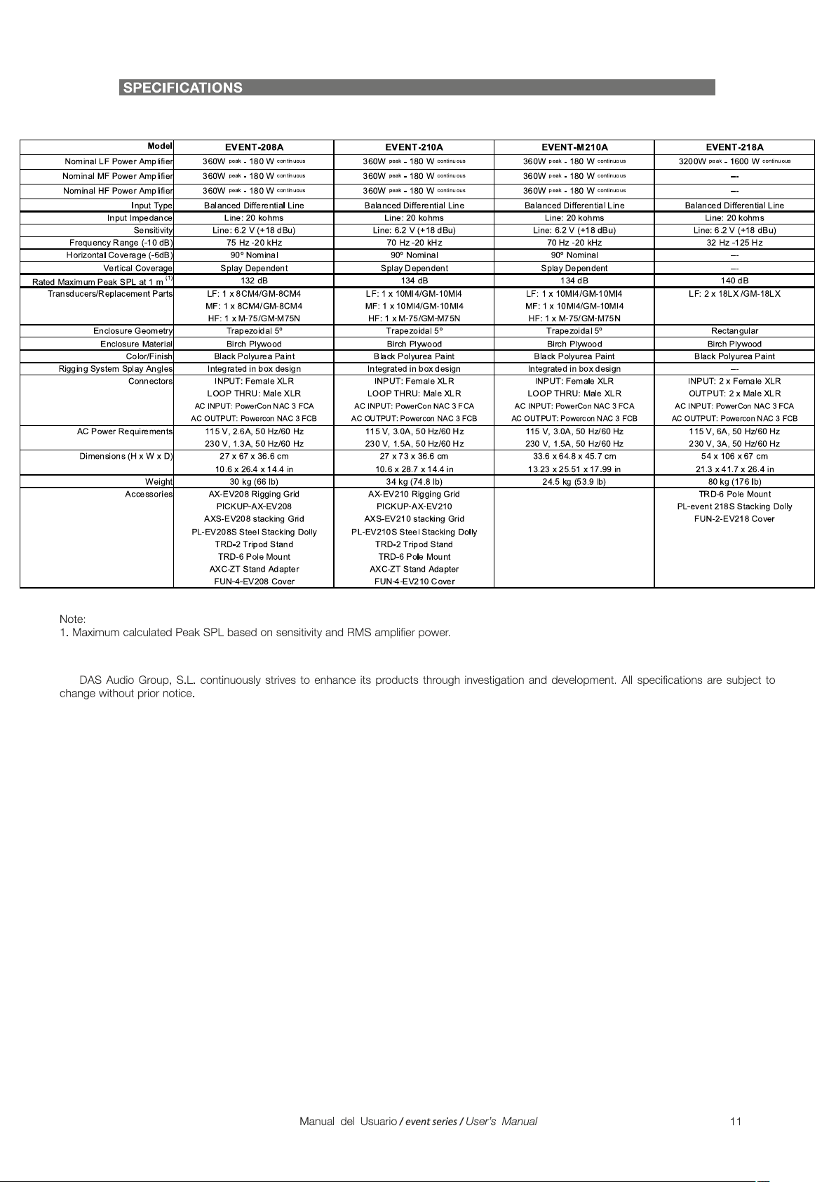
Page 12
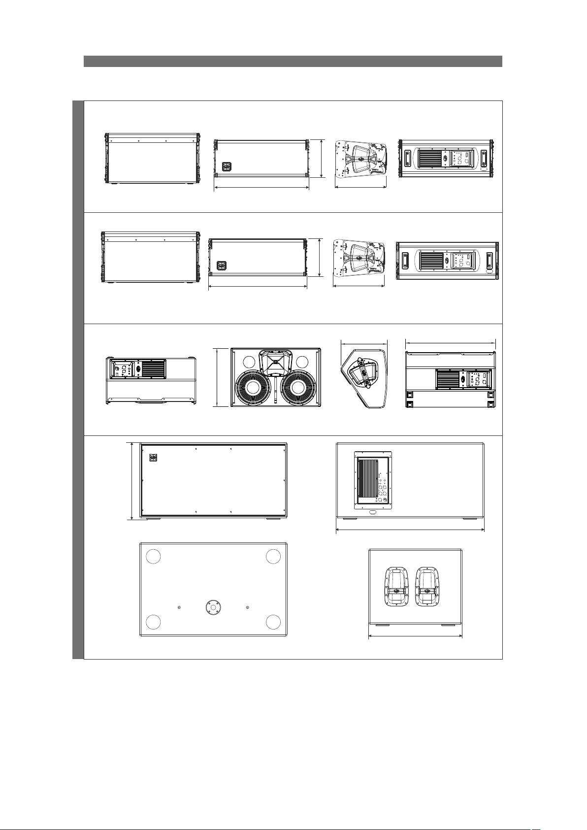
LINE DRAWINGS
ALL DIMENSIONS IN MILLIMETERS
270
EVENT-208A
EVENT-210A
EVENT-M210AEVENT-218A
Top View
Top View
Bottom View
Bottom View
420
670
Front View
Front View
730
Front View
Front View
270
Right View
Right View
Right View
336
336
332
Left View
Rear View
Rear View
Rear View
645
Rear View
540
Front View
Top View
1060
Rear View
670
Right View
12
Manual del Usuario / event series / User’s Manual
Page 13
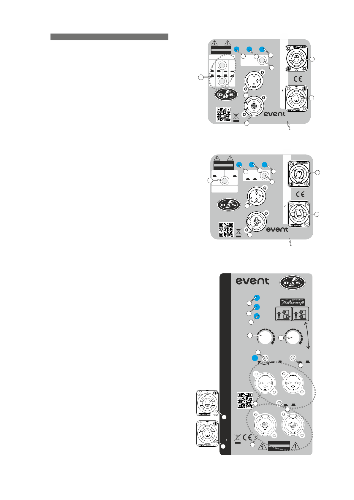
AMPLIFIER
Description
1) INPUT :
1/4” Jack+XLR combined socket-type input signal connector.
This is a balanced connector just like the LOOP THRU connector
with the following pin assignments:
1 or S =GND (ground)
2 or T =(+) Non inverted input
3 or R =(-) Inverted input
2) LOOP THRU (except EVENT-218A):
XLR-type output signal connector for connecting several units
together and sending them all the same signal.
2) SATELLITE OUTPUT (only EVENT-218A):
A and B, XLR-type output signal connectors for connecting
several units together and sending them all the same input signal or
filtered signal (by using THRU/HPF).
3) LIMIT :
Red LED indicates amplifier saturation. Amplifier limiter indicator
lights.
4) SIGNAL :
Green LED indicates signal presence.
5) ON :
Green LED indicates that the unit is ON.
MAX. 11 UNITS EVENT-208A-230
5
8
230V
1.3A 50Hz/60Hz
DO NOT EXPOSE THIS EQUIPMENT
NUMBER OF UNITS
9
RISK OF ELECTRIC SHOCK
DO NOT OPEN
CAUTION
TO RAIN OR MOISTURE
4
LIMIT SIGNAL ON
3
4
PUSH FOR
DOWNFILL
PRESET
81 6
LOOP THRU
2
DAS Audio Group, S.L. (Valencia)
MADE IN SPAIN
1
INPUT
line array
Model: EVENT-208A-230
Modelo
EVENT-208A and EVENT-210A amplifier label
DO NOT OPEN
LIMIT SIGNAL ON
RISK OF ELECTRIC SHOCK
CAUTION
DO NOT EXPOSE THIS EQUIPMENT
TO RAIN OR MOISTURE
1 UNIT 2 UNITS
9
LOW FREQUENCY
DECOUPLING
DAS Audio Group, S.L. (Valencia)
MADE IN SPAIN
3
90Hz HPF
ON/OFF
2
4
LOOP THRU
MAX. 9 UNITS EVENT-M210A-230
5
8
230V
1.5A 50Hz/60Hz
INPUT
11
10
11
10
6) LEVEL (only EVENT-218A):
Potentiometer for adjusting the unit level.
7) LOW-PASS (only EVENT-218A):
Button for adjusting the upper cut-off frequency for the
subwoofer unit. We recommend a cut-off frequency of 100 Hz.
8) DOWN-FILL PRESET (only EVENT-208A and EVENT-210A):
Press the button to select the Down-Fill preset.
8) 90 Hz HPF ON/OFF (only EVENT-M210A):
Press the button to select the HPF.
8) CARDIOID PRESET (only EVENT-218A):
Press the button to select the Cardioid preset.
9) NUMBER OF UNITS (except EVENT-218A):
Press the buttons to select the appropriate preset for this
number of units (please, see the label).
10) AC INPUT :
PowerCon NAC3FCA mains connector (inserted, rotated and
locked for ON). Only use this equipment with an appropriate
mains cord.
11) AC OUTPUT :
PowerCon NAC3FCB connector for AC loop thru (see unit’s
label)). Only use this equipment with an appropriate mains
cord.
12) POLARITY :
Switch for inverting the phase of the unit.
13) HPF/THRU (only EVENT-218A):
‘SATELLITE OUTPUT’ selector to switch between full range
signal or pass filter with cut-off frequency of 100 Hz.
Manual del Usuario / event series / User’s Manual
1
series
Model: EVENT-M210A-230
EVENT-M210A amplifier label
AC OUTPUT
MAX. 4@230V / 1@115V UNITS EVENT-218A
11
50Hz/60Hz 690W
AC INPUT
10
100-230V
series
Model: EVENT-218A
3
4
5
6
2
1
DAS Audio Group, S.L. (Valencia)
LIMIT
SIGNAL
CARDIOID OMNI
ON
LEVEL
0
7
+6-oo
80Hz
12
POLARITY
- +
OUTPUT A OUTPUT B
SATELLITE X-OVER
INPUT A INPUT B
RISK OF ELECTRIC SHOCK
DO NOT OPEN
CAUTION
DO NOT EXPOSE THIS EQUIPMENT
TO RAIN OR MOISTURE
EVENT-218A amplifier label
Modelo
MADE IN SPAIN
F
R
LOW-PASS
100Hz
125Hz
CARDIOID
HPF/THRU
13
F
F
PRESET
R F
8
13
Page 14
ON / OFF
A sound system should be switched on
sequentially. Switch on the self-powered units last
in your sound system (switch on the subwoofer
before the mid-high system). Switch on the sound
sources such as CD players or turntables, then the
mixer, then the processors, and finally the selfpowered unit. If you have several units, it is
recommended that you switch them on
sequentially one at a time.
Follow the inverse order when switching off,
turning self-powered units off before any other
element in the sound system.
Disconnect the device by removing the mains
connector from the mains socket. The mains
connector and mains socket must always be freely
accessible and never covered or blocked in any
way.
The models use a power cable equipped with
a Neutrik PowerCon NC3FCA connector. Power
can be daisy chained via the NC3FCB output
connector (see details on product label).
IMPORTANT: Do not disconnect the unit
while in use.
Ensure that the device is disconnected from
the mains by observing that the ON LED is turned
off. Please note that the ON LED can stay on for
several seconds after the mains power has been
disconnected.
Normally it is enough just to let the unit cool
down after you have corrected the problem so that
the system functions properly again.
Keep grilles clean and dust-free.
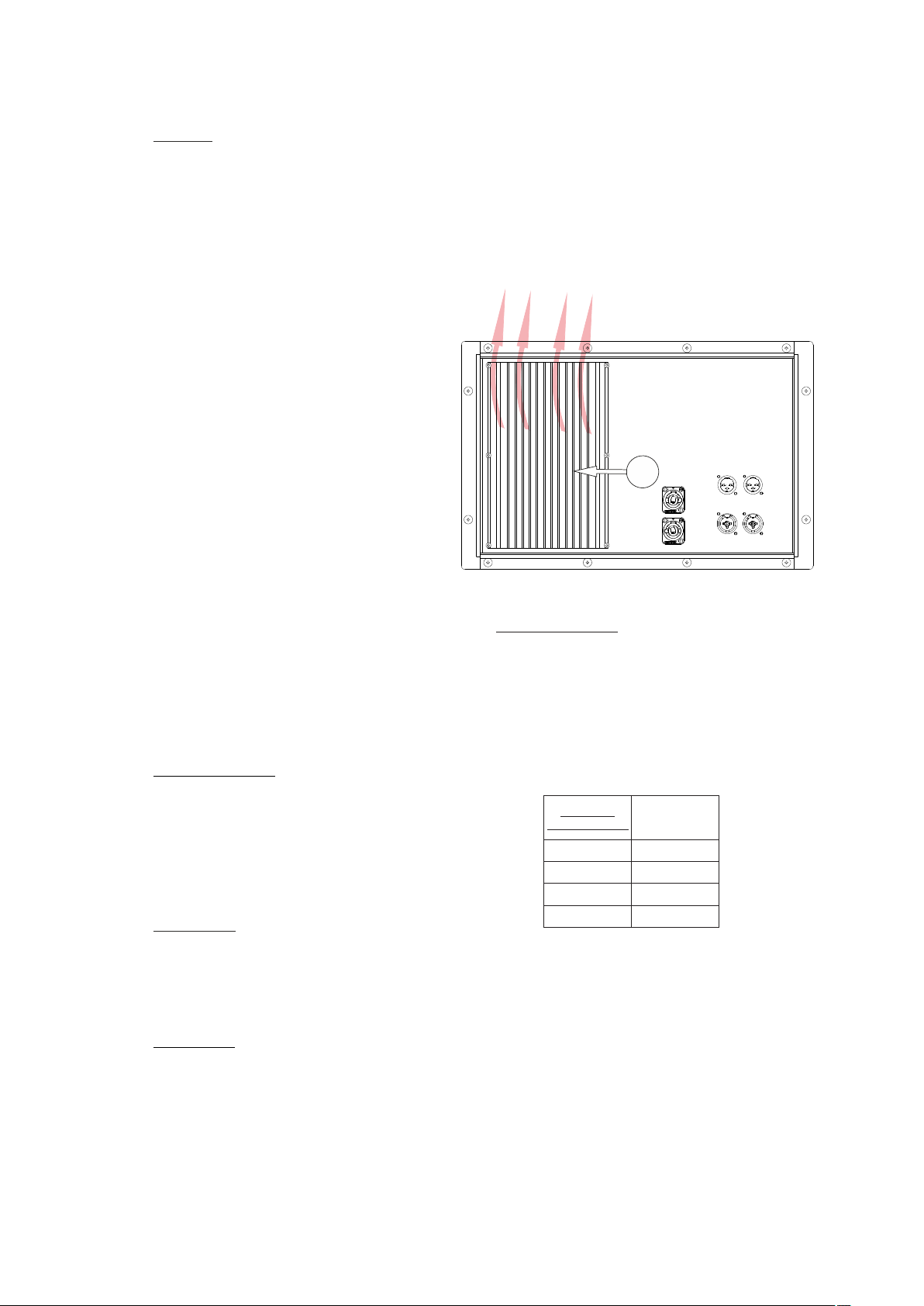
Air circulates from the bottom to the top of the
amplifier.
Heatsink
HeatsinEkV oEfN T- 218A amplifier
Low mains voltage
If mains voltage falls below the shutdown
voltage for the unit, it will stop playing. When
acceptable levels are regained, the unit will switch
back on automatically.
Overload indicator
This device has an indicator (LIMIT LED) that
lights when the signal is excessive.
The indicator should not be lit continuously.
This distorts the signal (quickly fatiguing your ears)
and may damage the speakers. Therefore, it is
recommended that you never work with this LED
on; at most it should blink only occasionally.
Equalisation
The unit does not need extreme settings of
equalisation to produce quality sound. Avoid high
levels of gain on the equalisers. Gain values above
+3 dB on a console’s EQ are not recommended.
Overheating
This equipment does not normally overheat
during normal conditions of use. When overheating
occurs, the unit protects itself. You should then
find out why and if necessary contact an
authorised dealer for technical assistance.
Therefore the current consumed by a 115V
version is double the 230V version to achieve the
same acoustic power level.
Pink Noise
Mains 230 Vrms
EVENT-208A
EVENT-210A
EVENT-M210A
EVENT-218A
1/3 Power
1.3A
1.5A
1.5A
3A
14
Manual del Usuario / event series / User’s Manual
Page 15
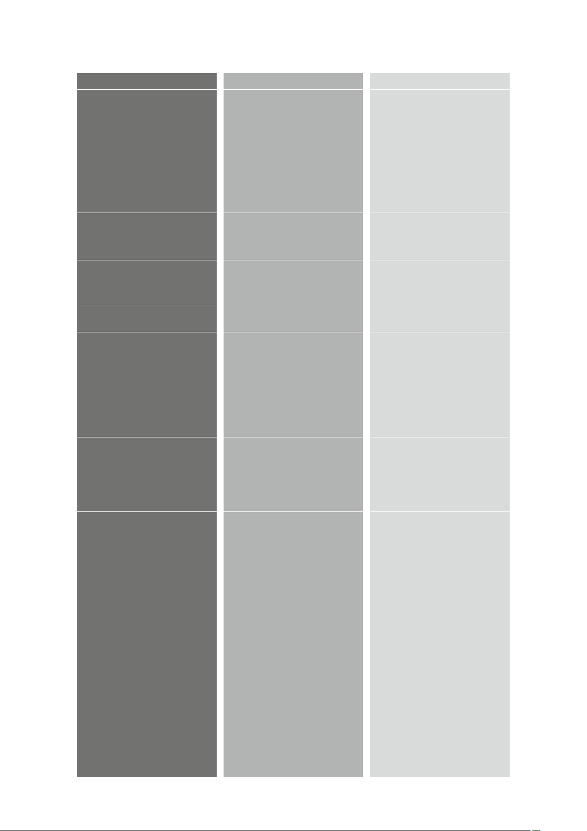
Troubleshooting
PROBLEM
CAUSE
SOLUTION
No sound from the unit. The
SIGNAL LED does not light up.
Full power cannot be obtained. The
LIMIT LED never lights up.
Sound is distorted. The LIMIT LED
is not on, or only lights up
occasionally.
Sound is distorted and very loud
and LIMIT LED lights up.
Hum or buzz when a mixer is
connected to the unit.
Hum or buzz when using lighting
controls in the same building.
The ON LED does not light up when
the mains connector is connected
and the unit is switched to ON.
1 – The signal source is sending no
signal.
2 – Defective cable.
3 - The amplifier has overheated.
The signal source does not have a
hot enough output.
The mixer or signal source is
distorting.
The system is overloaded and has
reached maximum power.
1.– The console probably has unbalanced outputs. You may be using
an i ncor re c t un-b ala nced t o
balanced cable.
2.– The mixer and the powered
speaker are not plugged into the
same mains outlet.
3.– The audio signal cable is too
long or too close to an AC cable
1.– The audio signal cable is too
long or too close to the lighting
cable.
2.– On a sound system with threephase AC, the lighting equipment
and the UNIT are connected to the
same phase.
1.– Bad or loose AC connection to
the UNIT or the mains outlet.
2 – Faulty AC cable.
3 – Blown Fuse.
4 - The mains voltage is out of
range.
1 – Check that the mixer or sound
source is sending signal to the UNIT.
2 – Check that the cable from the
sound source to the UNIT is
connected correctly. Replace the
cable if defective.
3 - Allow the unit to cool down for
some minutes and it will function
again. Check the main output level
of the mixer or channel gains since
the unit will have been functioning
with excessive levels.
If using a mixer, use the balanced
ou t p u t i f a v a i l a b le. U s e a
professional mixer with a hotter
output.
Turn mixer channel gains down.
Check that none of your signal
sources are distorting.
Turn down the mixer's output.
1.– Read the appendix of this
manual to make a correct unbalanced to balanced cable.
2.– Connect the mixer and the unit
to the same mains outlet.
3.– Use a cable that is as short as
possible and/or move the audio
signal cable away from mains
cables.
1.– Move the audio signal cable
away from lighting cables. Try to find
out at what point the noise is leaking
into the system.
2.– Connect the sound system to a
different phase than the lights. You
may need the help of an electrician.
1.– Check your connections.
2.– Check the cables, connectors
and AC power with a suitable mains
tester.
3.- Replace the blown fuse for
another of the same type and size.
4.- If the multimeter determines that
the mains voltage is out the range,
you may need the assistance of an
electrician to find an appropriate
solution.
Manual del Usuario / event series / User’s Manual
15
Page 16

RIGGING SYSTEM
Warning
Due to the numerous images needed to
explain the event series array system setup, this
manual can´t offer all the necessary information to
rig the DAS Audio system. In this document we
only reflect the safety precautions and a summary
of the elements.
To log in to the complete information, please
consult Rigging Manual, which you will find on
the web page www.dasaudio.com.
To perform any operations related to flying the
system, read the present document first and act
on the warnings and advice given. The goal is to
allow the user to become familiar with the
mechanical elements required to fly the acoustic
system, as well as the safety measures to be
taken during set-up and teardown.
Only experienced installers with adequate
knowledge of the equipment and local safety
regulations should fly speaker boxes. It is the
user´s responsibility to ensure that the systems to
be flown (including flying accessories) comply with
state and local regulations.
The working load limits in this manual are the
results of tests by independent laboratories. It is
the user´s responsibility to follow and comply with
safety factors, resistance values, periodical
supervisions and warnings given in this manual.
Product improvement by means of research and
development is on going at DAS Audio Group,
S.L. Specifications are subject to change without
notice.
It is common practice to apply 5:1 safety
factors for enclosures and static elements. For
slings and elements exposed to material fatigue
due to friction and load variation the following
ratios must be met; 5:1 for steel cable slings; 4:1
for steel chain slings and 7:1 for polyester slings.
Thus, an element with a breaking load limit of
1000 kg may be statically loaded with 200 kg (5:1
safety factor) and dynamically loaded with 142 kg
(7:1 safety factor).
When a system is flying, the working load must
be lower than the resistance of each individual
flying point in the enclosure, as well as each box.
Hanging hardware should be regularly inspected
and suspect units replaced if in doubt. This is
important to avoid injury and absolutely no risks
should be taken in this respect. It is highly
recommended that you implement an inspection
and maintenance program on flying elements,
including reports to be filled out by the personnel
that will carry out the inspections. Local
regulations may exist that, in case of accident,
may require you to prevent evidence of inspection
reports and corrective actions after defects were
found.
Absolutely no risks should be taken with
regards to public safety.
When flying enclosures from ceiling support
structures, extreme care should be taken to assure
the load bearing capabilities of the structures so
that the installation is absolutely safe. Do not fly
enclosures from unsafe structures. Consult a
certified professional if needed. All flying
accessories that are not supplied by D.A.S. Audio
are the user´s responsibility. Use at your own risk.
Accessories
The systems with event series are rigged (except
EVENT-218A) with the accessories AX-EV208 (and
PICKUP-AX-EV208 if you need another lift motor),
and AX-EV210 (and PICKUP-AX-EV210 if you need
another lift motor). To stack, you will need the
accessories AXS-EV208 or AXS-EV210. The EVENT-
218A only can use to stack.
The platforms PL-EV208S and PL-EV210S allow
the transport of up to four units (of EVENT-208A
and EVENT-210A, respectively), but PL-EV218S only
allows the transport of up to three units of EVENT-
218A.
16
Consult the Rigging Manual for more
information about the accessories.
The metal parts are made of steel, covered
with zinc and painting in black, with high
resistency screws which act to reinforce the
stacking and the rigging.
Next, we name the accessories with images.
Manual del Usuario / event series / User’s Manual
Page 17
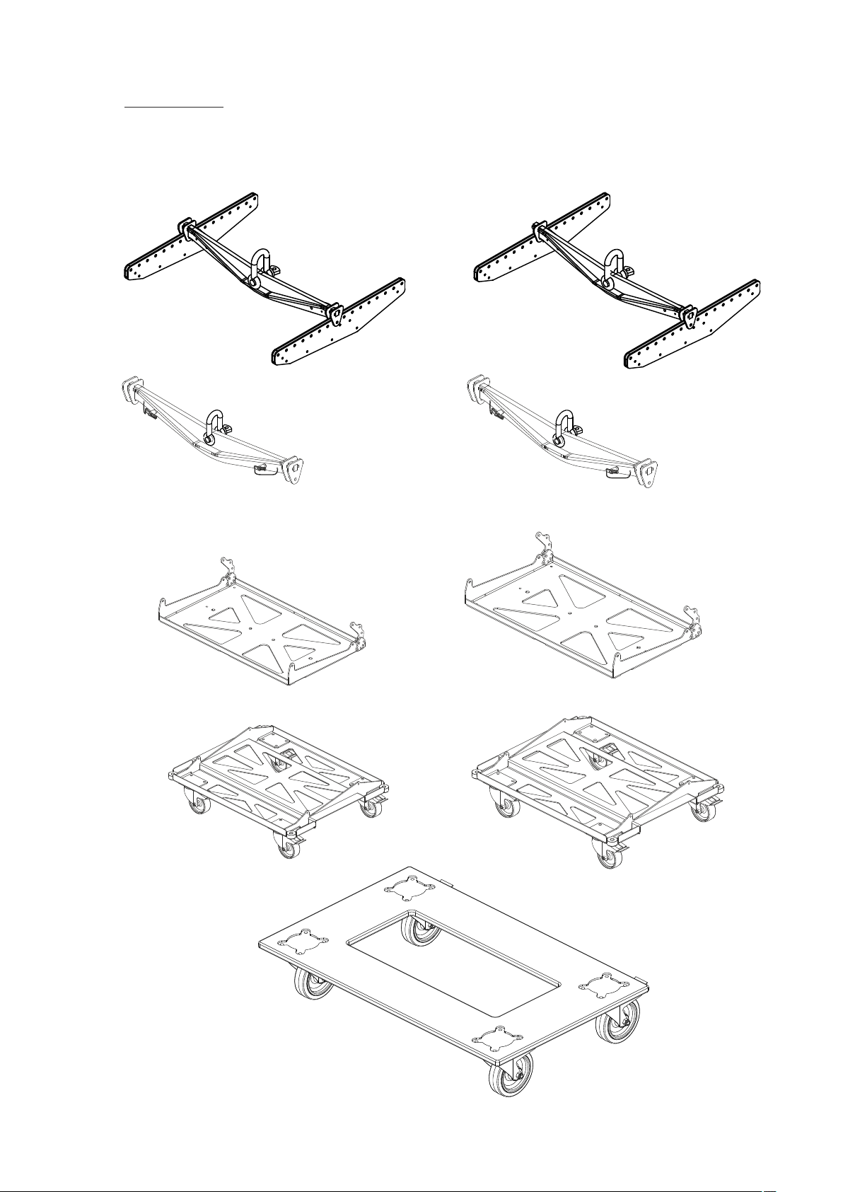
Accessories
To complete this information, please consult Rigging Manual, and other documents, which you will find
on the web page www.dasaudio.com.
AX-EV208
AXS-EV208
AX-EV210
PICKUP-AX-EV210PICKUP-AX-EV208
AXS-EV210
PL-EV208S
PL-EV210S
PL-EV218S
Manual del Usuario / event series / User’s Manual
17
Page 18
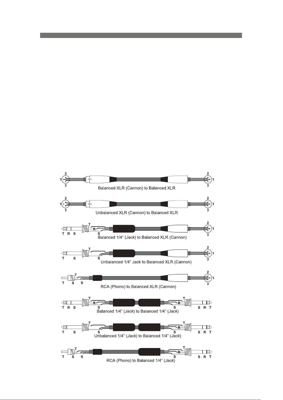
ANNEX : Line connections: unbalanced and balanced
There are two basic ways to transport an audio signal with microphone or line level:
Unbalanced line: Utilising a two conductor cable, it transports the signal as the voltage between them.
Electromagnetic interference can get added to the signal as undesired noise. Connectors that carry
unbalanced signals have two pins, such as RCA (Phono) and ¼” (6.35mm, often referred to as jack) mono. 3
pin connector such as XLR (Cannon) may also carry unbalanced signals if one of the pins is unused.
Balanced line: Utilising a three conductor cable, one of them acts as a shield against electromagnetic
noise and is the ground conductor. The other two have the same voltage with respect to the ground
conductor but with opposite signs. The noise that cannot be rejected by the shield affects both signal
conductors in the same way. At the device’s input the two signals get summed with opposite sign, so that
noise is cancelled out while the programme signal doubles in level. Most professional audio devices use
balanced inputs and outputs. Connectors that can carry balanced signal have three pins, such as XLR
(Cannon) and ¼” (6.35mm) stereo.
The graphs that follow show the recommended connection with different types of connectors to balanced
processor or amplifier inputs. The connectors on the left-hand side come from a signal source, and the ones
on the right hand side go to the inputs of the processor or amplifier. Note that on the unbalanced connectors
on the left-hand side, two terminals are joined inside the connector. If hum occurs with balanced to balanced
connections, try disconnecting the sleeve (ground) on the input connector. Note that the illustrations show
what should be connected to what, but that pin locations on an actual XLR connector are different. Also, pin
2 hot is assumed on XLR connectors.
18
Manual del Usuario / event series / User’s Manual
Page 19
www.dasaudio.com
UM_EV_04_EN
DAS Audio Group, S.L.
C/. Islas Baleares, 24
46988 Fuente del Jarro
Valencia, SPAIN
Tel. +34 96 134 0860
DAS Audio of America, INC.
6900 NW 52th Street
Miami, FL. 33166 - U.S.A.
TOLL FREE: 1 888 DAS 4 USA
DAS Audio Asia PTE. LTD.
3 Temasek Avenue, Centennial
Tower #34-36
Singapore 039190
Tel. +65 6549 7760
DAS do Brasil LTDA.
Rua Dos Andradas, 382 SL
Santa Efigênia, São Paulo
Brasil. CEP: 01208-000
Tel. +551133330764
 Loading...