

Page 1
User's Manual
line array
EVENT-26A / EVENT-115A
Antes de utilizar el equipo, lea la sección
“Precauciones de seguridad” de este manual.
Conserve este manual para futuras consultas.
Before operating the device, please read the
“Safety precautions” section of this manual.
Retain this manual for future reference.
Page 2

CONTENTS
SAF ET Y PREC AU TI ONS
WARRANTY
DEC LA RA TION OF CON FO RM ITY
INT RO DU CTION
CON FI GU RATIONS
2 x EVENT-26A + 2 x EVENT-115A
8 x EVENT-26A + 4 x EVENT-115A (flown subs)
8 x EVENT-26A + 4 x EVENT-115A
12 x EVENT-26A + 4 x EVENT-115A + 2 x EVENT-121A
12 x EVENT-26A + 4 x EVENT-218A
SPE CI FI CATIONS
LIN E D RAWING S
AMP LI FI ERS
Descriptions
ON / OFF
Overload indicator
Equalisation
Overheating
Low mains voltage
3
4
5
6 - 7
8 - 12
13
14
15 - 21
Current consumption
Troubleshooting
RIG GI NG SYSTEM
4 or 6 units mounting on a PL-EV26S flatbed dolly
Array mounting of groups of 4 units on a flatbed dolly
EVENT-115A array mounting
EVENT-26A array mounting “one by one”
EVENT-115A + EVENT-26A array mounting
Stacking EVENT-26A on EVENT-115A
Transporting
ANN EX : Line connections: unbalanced and balanced
22 - 31
32
Manual del Usuario / event series / User’s Manual
Page 3
Precauciones de Seguridad
line array
Cajas acústicas activas / Self-powered loudspeaker enclosures
Safety Precautions
El signo de exclamación dentro de un triángulo indica la
existencia de importantes instrucciones de operación y
mantenimiento en la documentación que acompaña al producto.
Conserve y lea todas estas instrucciones. Siga las advertencias.
ATENCIÓN: Es un producto clase A, por lo que en entornos
domésticos puede causar radio-interferencias, en cuyo caso el
usuario tendrá que tomar las medidas oportunas.
De acuerdo con EN55103-2, usar el equipo sólo en entornos E1,
E2, E3 ó E4.
No desconecte la tierra en el conector de alimentación pues es
peligroso e ilegal. Equipo de Clase I. El producto debe ser
conectado a un enchufe con toma de tierra. Sólo use este
equipo con el cable de red de alimentación adecuado para su
país.
El signo del rayo con la punta de flecha, alerta contra la
presencia de voltajes peligrosos no aislados. Para reducir el
riesgo de choque eléctrico, no retire la cubierta.
No instale el aparato cerca de ninguna fuente de calor como
radiadores, estufas u otros aparatos que produzcan calor. Debe
instalarse siempre sin bloquear la libre circulación de aire por las
aletas del radiador.
No exponga este equipo a la lluvia o humedad. No use este
aparato cerca del agua (piscinas y fuentes, por ejemplo). No
exponga el equipo a salpicaduras ni coloque sobre él objetos
que contengan líquidos, tales como vasos y botellas.
Equipo IP-43.
Este símbolo indica que el presente producto no puede ser
tratado como residuo doméstico normal, sino que debe
entregarse en el correspondiente punto de recogida de equipos
eléctricos y electrónicos.
The exclamation point inside an equilateral triangle is intended to
alert the users to the presence of important operating and
mainte nance (se rvicing ) instr uctions in the literature
accompanying the product. Heed all warnings. Follow all
instructions. Keep these instructions.
WARNING: This is a class A product. In a domestic environment
this product may cause radio interferences in which case the
user may be required to take adequate measures.
Use this product only in E1, E2, E3 or E4 environments
according to EN55103-2.
Do not remove mains connector ground, it is dangerous and
illegal. Class I device. The product must be connected to a
mains socket outlet with protective earth connection. Only use
this equipment with an appropriate mains cord for your country.
The lightning and arrowhead symbol warns about the presence
of uninsulated dangerous voltage. To reduce the risk of electric
shock, do not remove the cover.
Do not install near any heat sources such as radiators, heat
registers, stoves or other apparatus that produce heat. The
circulation of air through the heatsink must not be blocked.
Do not expose this device to rain or moisture. Do not use this
apparatus near water (for example, swimming pools and
fountains). Do not place any objects containing liquids, such as
bottles or glasses, on the top of the unit. Do not splash liquids
on the unit. IP-43 equipment.
This symbol on the product indicates that this product should
not be treated as household waste. Instead it shall be handed
over to the appicable collection point for the recycling of
electrical and electronic equipment.
Equipo diseñado para funcionar entre 15ºC y 45ºC con una
humedad relativa máxima del 95%, con un rango de ±10% de la
tensión nominal de alimentación indicada en la etiqueta trasera.
Si debe sustituir el fusible preste atención al tipo y rango.
El cableado exterior conectado al equipo requiere de su
instalación por una persona instruida o el uso de cables flexibles
ya preparados.
Si el aparato es conectado permanentemente, la instalación
eléctrica del edificio debe incorporar un interruptor multipolar con
separación de contacto de al menos 3mm en cada polo.
Para desconectar el dispositivo debe usar el enchufe.
Desconecte este aparato durante tormentas eléctricas,
terremotos o cuando no se vaya a emplear durante largos
periodos.
No emplace altavoces en proximidad a equipos sensibles a
campos magnéticos, tales como monitores de televisión o
material magnético de almacenamiento de datos.
Para EVENT-26A, la altura máxima de seguridad desde el suelo a
la base de la caja montada sobre trípode modelo TRD-2 (necesita
además AXS-EV26 ), con pies a 55 cm del eje del trípode, es:
1x EVENT-26A ------------->142 cm
2x EVENT-26A ------------->132 cm
El colgado del equipo sólo debe realizarse utilizando los herrajes
de colgado recomendados y por personal cualificado. No
cuelgue la caja de las asas.
No existen partes ajustables por el usuario en el interior de este
equipo. Cualquier operación de mantenimiento o reparación
debe ser realizada por personal cualificado. Es necesario el
servicio técnico cuando el equipo se haya dañado de alguna
forma, como que haya caído líquido o algún objeto en el interior
del aparato, haya sido expuesto a lluvia o humedad, no funcione
correctamente, haya recibido un golpe o su cable de red esté
dañado.
Limpie con un paño seco. No use limpiadores con disolventes. Clean only with a dry cloth. Do not use any solvent based
55 cm
Working temperature ranges from 15ºC to 45ºC with a relative
humidity of 95%, with ±10% of the rated main voltage value
indicated on the rear label. If the fuse needs to be replaced,
please pay attention to correct type and ratings.
The outer wiring connected to the device requires installation by
an instructed person or the use of a flexible cable already
prepared.
If the apparatus is connected permanently, the electrical system
of the building must incorporate a multipolar switch with a
separation of contact of at least 3mm in each pole.
To disconnect the device, you should use the mains plug. Unplug
this apparatus during lightning storms, earthquakes or when
unused for long periods of time.
Do not place loudspeakers in proximity to devices sensitive to
magnetic fields such as television monitors or data storage
magnetic material.
For EVENT-26A, the maximum safety height from floor to bottom
of enclosure when mounting on a TRD-2 tripod (it needs also
AXS-EV26), with legs spread 55cm from the central pole, is:
1x EVENT-26A ------------->142 cm
2x EVENT-26A ------------->132 cm
The appliance should be flown only from the rigging points and
by qualified personnel. Do not suspend the box from the
handles.
No user serviceable parts inside. Refer all servicing to qualified
service personnel. Servicing is required when the apparatus has
been damaged in any way, such as power-supply cord or plug is
damaged, liquid has been spilled or objects have fallen into the
apparatus, the apparatus has been exposed to rain or moisture,
does not operate normally or has been dropped.
cleaners.
Manual del Usuario / event series / User’s Manual
3
Page 4

GARANTÍA
Todos nuestros productos están garantizados por un periodo de 24
meses desde la fecha de compra.
Las garantías sólo serán válidas si son por un defecto de
fabricación y en ningún caso por un uso incorrecto del producto.
Las reparaciones en garantía pueden ser realizadas,
exclusivamente, por el fabricante o el servicio de asistencia técnica
autorizado.
Para solicitar reparación en garantía es imprescindible que el
producto no haya sido previamente manipulado e incluir una
fotocopia de la factura de compra.
Todos los detalles relativos a la garantía (como las garantías
extendidas) los puede encontrar en la sección SOPORTE en nuestra
web: www.dasaudio.com
WARRANTY
All our products are warrantied against any manufacturing defect
for a period of 24 months from date of purchase.
The warranty excludes damage from incorrect use of the product.
All warranty repairs must be exclusively undertaken by the factory
or any of its authorised service centers.
To claim a warranty repair, do not open or intend to repair the
product.
All the details related to the warranty (such as extended warranties)
can be found in the SUPPORT section on our website:
www.dasaudio.com
4
Manual del Usuario / event series / User’s Manual
Page 5

DECLARACIÓN DE CONFORMIDAD
DECLARATION OF CONFORMITY
DAS Audio Group, S.L.
C/ Islas Baleares, 24 - 46988 - Pol. Fuente del Jarro - Valencia. España
(Spain).
Declara que los modelos EVENT-26A y EVENT-115A:
Declares that models EVENT-26A and EVENT-115A:
Cumple con los objetivos esenciales de las Directivas:
Abide by essential objectives relating Directives:
l Directiva de Baja Tensión (Low Voltage Directive) 2014/35/UE
l Directiva de Compatibilidad Electromagnética (EMC) 2014/30/UE
l Directiva RoHS 2011/65/UE
l Directiva RAEE (WEEE) 2012/19/UE
Y es conforme a las siguientes Normas Armonizadas Europeas:
In accordance with Harmonized European Norms:
l EN 60065:2014.- Audio, video and similar electronic apparatus. Safety
requirements.
l EN 55032:2012.- Electromagnetic compatibility of multimedia equipment.
Emission requirements.
l EN 55103-2:2009.- Electromagnetic compatibility. Product family standard
for audio, video, audio-visual and entertainment lighting control apparatus
for professional use. Part 2:Immunity.
l EN 50581:2012.- Technical documentation for the assessment of electrical
and electronic products with respect to the restriction of hazardous
substances.
Manual del Usuario /event series / User’s Manual
5
Page 6
INTRODUCTION
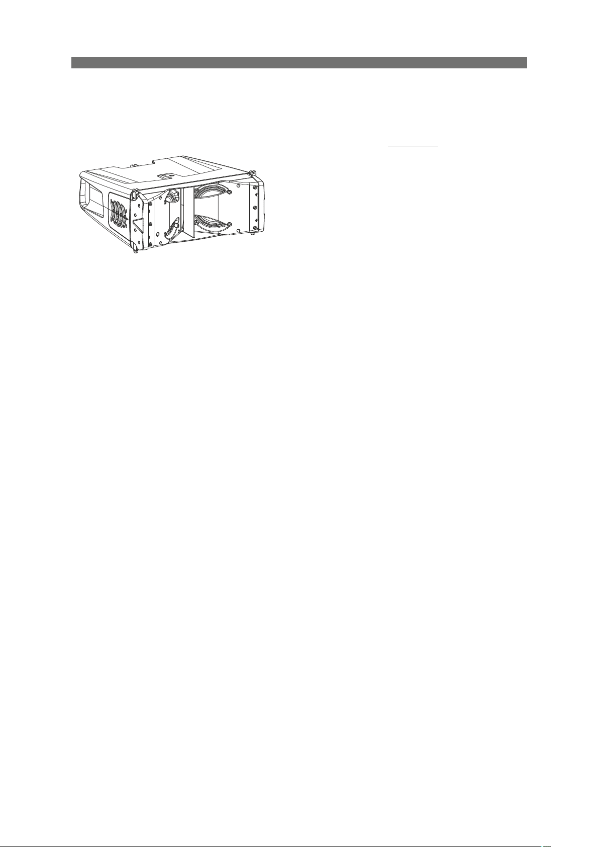
For portable live sound applications, or fixed installations in almost any type of small-mid sized venue, the
EVENT-26A Line Array has been designed to provide exceptional sound and coverage, steadfast reliability and value
beyond comparison.
The EVENT-26A Array incorporates a high frequency waveguide and horn assembly designed with the same
technology, tools and knowledge as the aero series.
Features
- Ultra-compact, lightweight powered line array
- High-efficiency Class D amplifier with SMPS Dual
voltage mains for use anywhere in the world
- 100º wide coverage
- 2 x 6.5″, 6Mi, loudspeakers in a symmetric V-shape
configuration
- Easy system configuration thanks to DAScontrolTM
- High-end 24-bit DSP with LCD screen FIR processing
technology for constant phase response FSSTM Fast Set
Splay rigging for quick deployment
EVENT-26A
EVENT-26A
The EVENT-26A is a symmetrical, ultra-compact, two-way powered line array system. Designed by DAS
engineers to deliver stunning performance and exceptional ease-of-use, the stylish polypropylene cabinet design
offers a highly portable and road-worthy system. A comprehensive range of accessories makes the EVENT-26A ideal
for small to mid-size rental and installation applications.
The EVENT-26A combines two 6.5" transducers and a single M-60 compression driver in a rugged yet lightweight
polymer cabinet. The symmetric "V" shaped configuration of the cone transducers provides consistent 100º of
horizontal coverage down to 200 Hz. The M-60 compression driver is coupled to an advanced waveguide design that
provides control of the vertical dispersion as well as precise coupling between units when used in vertical arrays.
Powered by a two-channel Class D amplifier providing 800 Wpeak power, the amp´s rear panel includes quality
Neutrik® XLR and powerCON connectors. The DAScontrolTM interface makes the preset selection for the number
of units in the array both fast and simple. An onboard DSP featuring a 24-bit high-end processor handles X-over, EQ,
delay, and limiter functions. The powerful FIR filtering technology incorporated in the EVENT-26A offers constant
phase response which translates to transparent sound and exceptional clarity, improving the listening experience.
Streamlined deployment of EVENT-26A arrays is possible thanks to the innovative FSSTM (Fast Set Splay) rigging
system developed to permit angle selection while stacked on dollies. The stainless steel rigging hardware allows
flown arrays of up to 16 units in 1º steps from 0º to 10º.
Low-frequency reinforcement for the EVENT-26A is provided by its flyable companion subwoofer the EVENT-115A.
6
Manual del Usuario / event series / User’s Manual
Page 7
EVENT-115A
- Active front-loaded subwoofer system
- 1 x 15″ DAS 15FW4 loudspeaker
- High-efficiency Class D amplifier with SMPS Dual
voltage mains for use anywhere in the world
- Easy system configuration thanks to DAScontrolTM
High-end 24-bit DSP with LCD screen
- EVENT-115A compatible rigging hardware
EVENT-115A
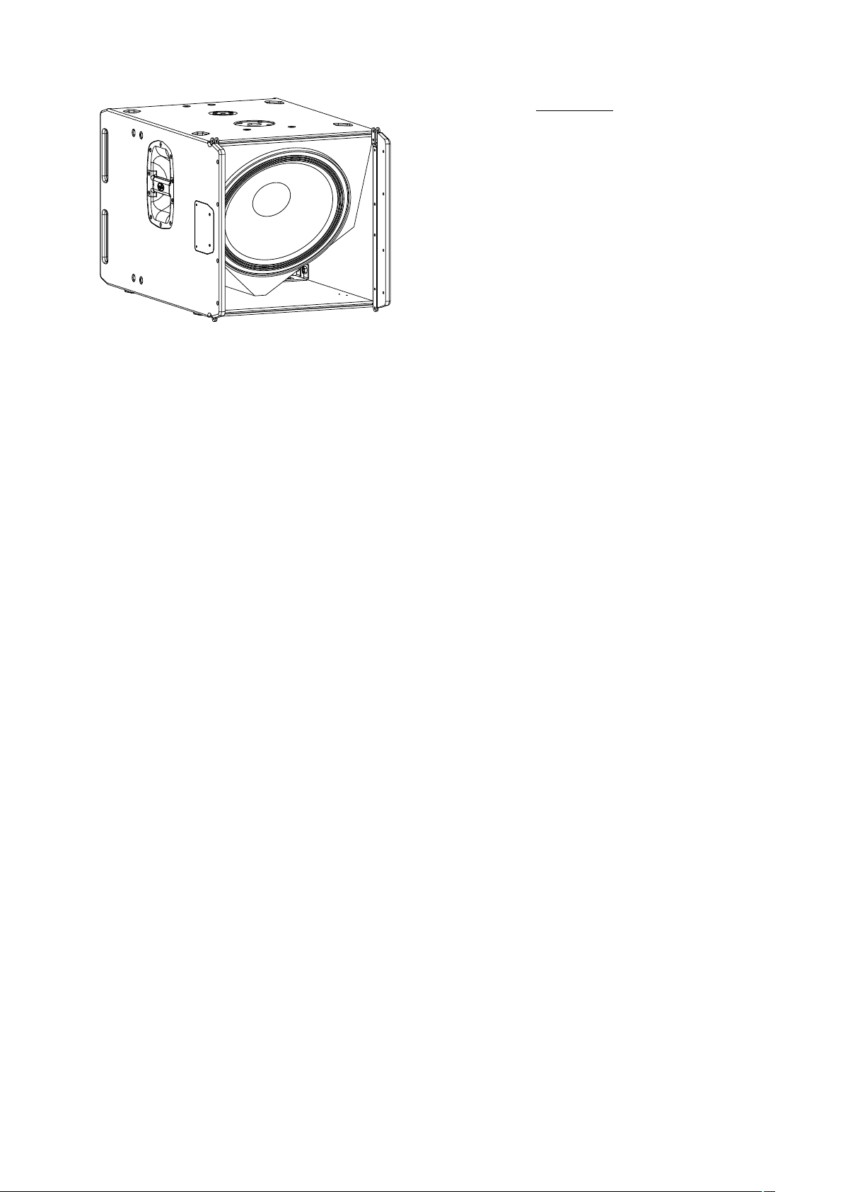
The EVENT-115A is a compact powered subwoofer system which uses a front-loaded 15” low frequency
transducer developed by DAS. Designed as the companion subwoofer for the EVENT-26A, they share a compatible
rigging system which allows the EVENT-26A to be flown from or stacked above the EVENT-115A.
The 15FW4 15" loudspeaker used in the EVENT-115A has been engineered by DAS to provide outstanding
performance and reliability. The 15FW4 speaker design has been optimized using Finite Element Analysis (FEA) and
incorporates an extended 3″ voice coil for high-efficiency and long excursion offering a power handling capacity of
1200 Wprogram. Efficient cooling is assured thanks to the 15FW4´s vented pole piece and abundant apertures in the
speaker´s back plate keeping power compression to a minimum while providing high acoustic output over extended
periods.
Driving the DAS 15FW4 loudspeaker is a cutting-edge 1200 Wpeak Class D amplifier. On the rear panel, quality
Neutrik XLR input connectors and stereo “loop thru” output connections are available to provide signal for the
EVENT-26A systems. Thanks to the digital presets accessible by way of the DAScontrol™ interface on the rear of the
cabinet, set-up of a complete systems is extremely easy.
The EVENT-115A cabinet is constructed from Birch plywood using a robust enclosure design and finished with the
DAS ISO-flex protective coating for extended durability. The rigging hardware is compatible with the EVENT-26A
allowing it to be flown directly below or stacked above the subwoofer unit. A top located pole mount socket is available
allowing the EVENT-26A to be used in a combo configuration.
Manual del Usuario / event series / User’s Manual
7
Page 8
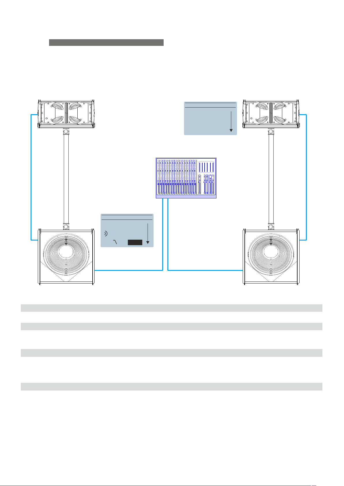
CONFIGURATIONS
AXC-ZT
TRD-7
AXS-EV26
2 x EVENT-26A + 2 x EVENT-115A
MAIN MENU
BACK
No.of U: 1U
DownFill: off
Speaker cabling
SC2 2m XL R microphone signal balanced cable
SC20 20m XL R microphone signal balanced cable
Rigging frames
AXS-EV26 Stacking bumper for E VENT-26A
TRD-7 Telescopic pole mount
AXC-ZT Speaker adaptor for pole mount
Dollies
MAIN MENU
BACK
PRESET: loud
LPF: <Top>
UnitsProcessors
2
2
2
2
2
PL-EV115S Plywood transport dolly for EVENT-115A
PL-EV26S Steel transport dolly for EV ENT-26A
8
1
1
Manual del Usuario / event series / User’s Manual
Page 9
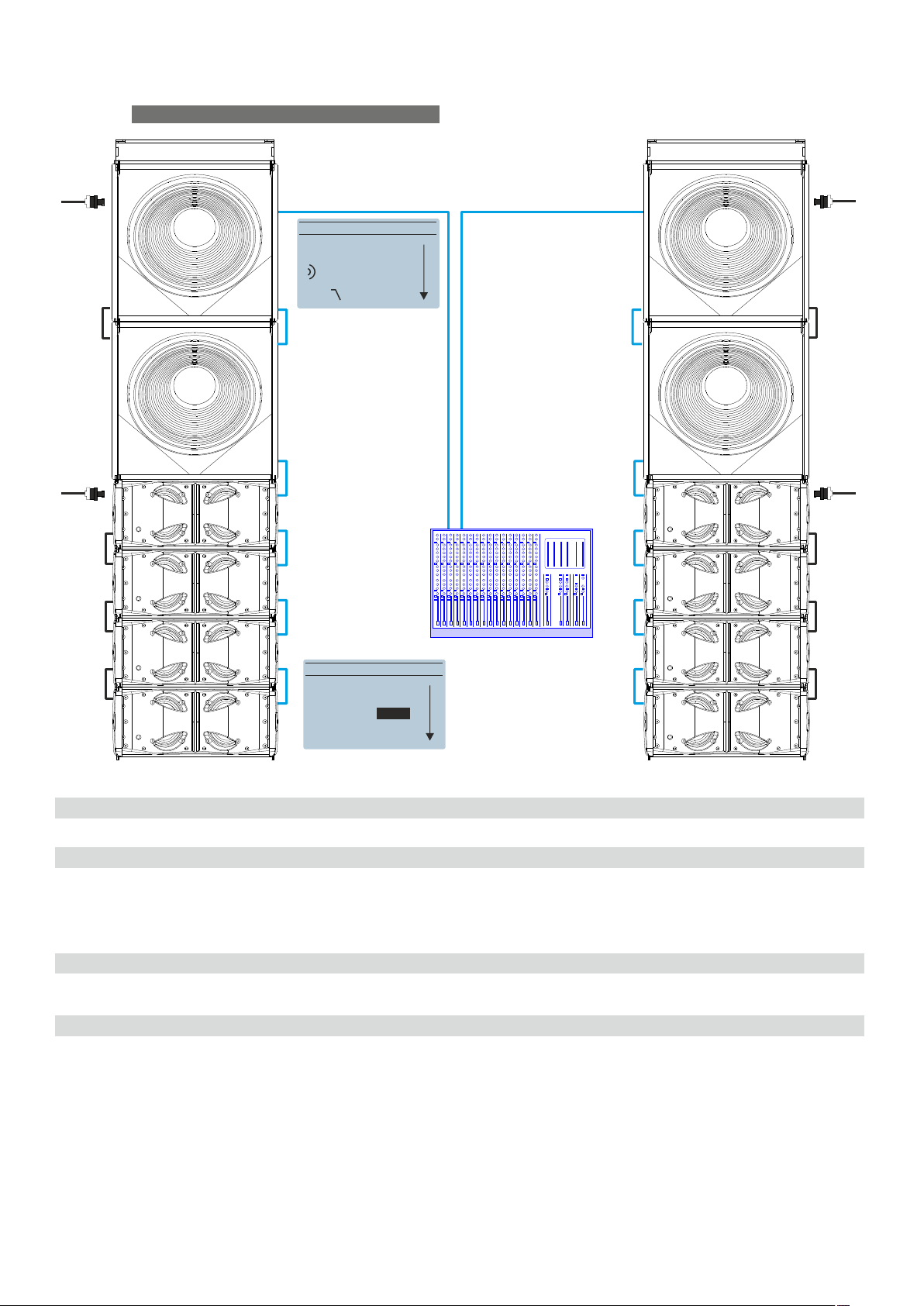
CONFIGURATIONS (cont’d)
8 x EVENT-26A + 4 x EVENT-115A
MAIN MENU
BACK
PRESET: loud
LPF: Top
AX-EV26
Processors
Speaker cabling
SC-1 1m XL R microphone signal balanced cable
SC-20 20m XL R microphone signal balanced cable
SC-05 0.5m XL R microphone signal balanced cable
PWCONL INK-09 0.9m powerCON “jumper” NAC3FCB cable
Rigging frames
Dollies
PL-EV115S Plywood transport dolly for EVENT-115A
PL-EV26S Steel transport dolly for EV ENT-26A
MAIN MENU
BACK
No.of U: <4U>
DownFill: off
Units
4
2
6
8
2AX-EV26 Rigging bumper for EV ENT-26A / EVEN T-115A
2JP-EV26 Joining plate for EV ENT-26A / EVEN T-115A
2
2
Manual del Usuario / event series / User’s Manual
9
Page 10
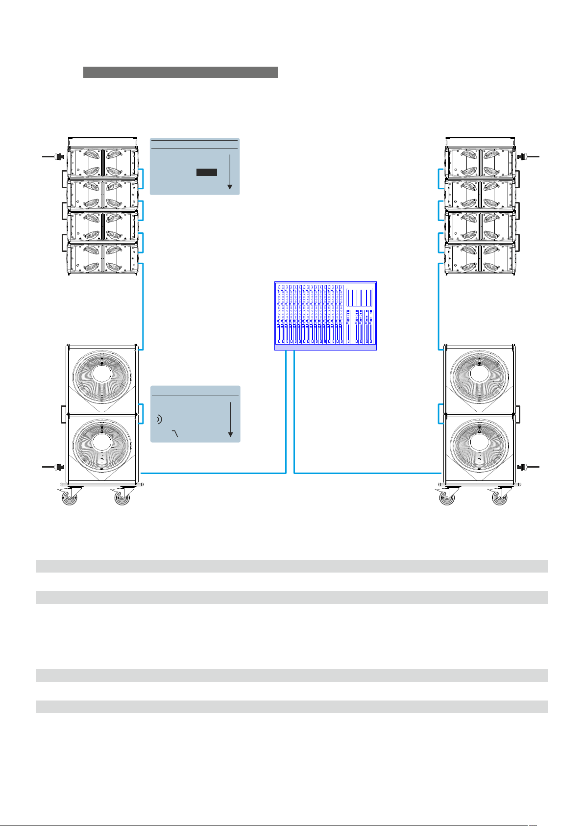
CONFIGURATIONS (cont’d)
AX-EV26
MAIN MENU
BACK
No.of U: <4U>
DownFill: off
8 x EVENT-26A + 4 x EVENT-115A
MAIN MENU
PRESET: loud
LPF: Top
PL-EV115S
Speaker cabling
SC-1 1m XL R microphone signal balanced cable
SC-5 5m XL R microphone signal balanced cable
SC-05 0.5m XL R microphone signal balanced cable
SC-20 20m XL R microphone signal balanced cable
PWCONL INK-09 0.9m powerCON “jumper“ NAC3FCB cable
Rigging frames
Dollies
BACK
UnitsProcessors
2
2
6
2
8
2AX-EV26 Rigging bumper for EV ENT-26A / EVEN T-115A
PL-EV115S Plywood transport dolly for EVENT-115A
PL-EV26S Steel transport dolly for EV ENT-26A
10
2
2
Manual del Usuario / event series / User’s Manual
Page 11
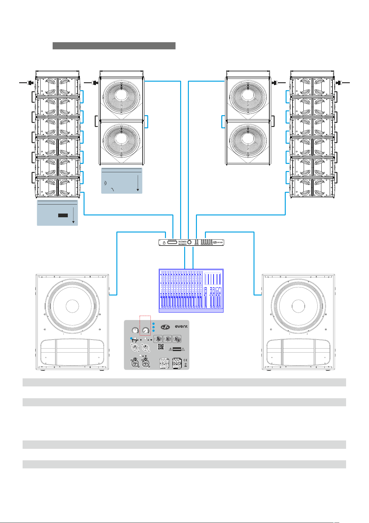
CONFIGURATIONS (cont’d)
AX-EV26A
MAIN MENU
BACK
No.of U: <6U>
DownFill: off
12 x EVENT-26A + 4 x EVENT-115A + 2 x EVENT-121A
MAIN MENU
BACK
PRESET: loud
LPF: Top
DSP-226 2 IN x 6 OUT digital signal processor
Speaker cabling
SC-1 1m XL R microphone signal balanced cable
SC-05 0.5m XL R microphone signal balanced cable
SC-20 20m XL R microphone signal balanced cable
PWCONL INK-09 0.9m powerCON “jumper“ NAC3FCB cable
Rigging frames
Dollies
PL-EV115S Plywood transport dolly for EVENT-115A
PL-EV26S Steel transport dolly for EV ENT-26A
INPUT A
LPF 63Hz
LEVEL
LOW-PASS
0
80Hz
+6-oo
63Hz
POLARITY
- +
OUTPUT A OUTPUT B
SATELLITE X-OVER
HPF/THRU
LIMIT
SIGNAL
ON
100Hz
CARDIOID
OMNI CARDIOID
PRESET
F
R F
www.dasaudio.com
115/230 V~ 50/60Hz 0W83
INPUT B
DAS Audio Group, S.L. (Valencia)
MADE IN SPAIN
CARDIOID
F
AC INPUT
RFR
DO NOT EXPOSE THIS EQUIPMENT
AC OUTPUT
MAX. 3@230V / 1@115V
UNITS EVENT-121A
series
Model: EVENT-121A
F
RISK OF ELECTRIC SHOCK
DO NOT OPEN
CAUTION
TO RAIN OR MOISTURE
F
UnitsProcessors
1
2
10
2
12
2AX-EV26 Rigging bumper for EV ENT-26A / EVEN T-115A
2
2
Manual del Usuario / event series / User’s Manual
11
Page 12
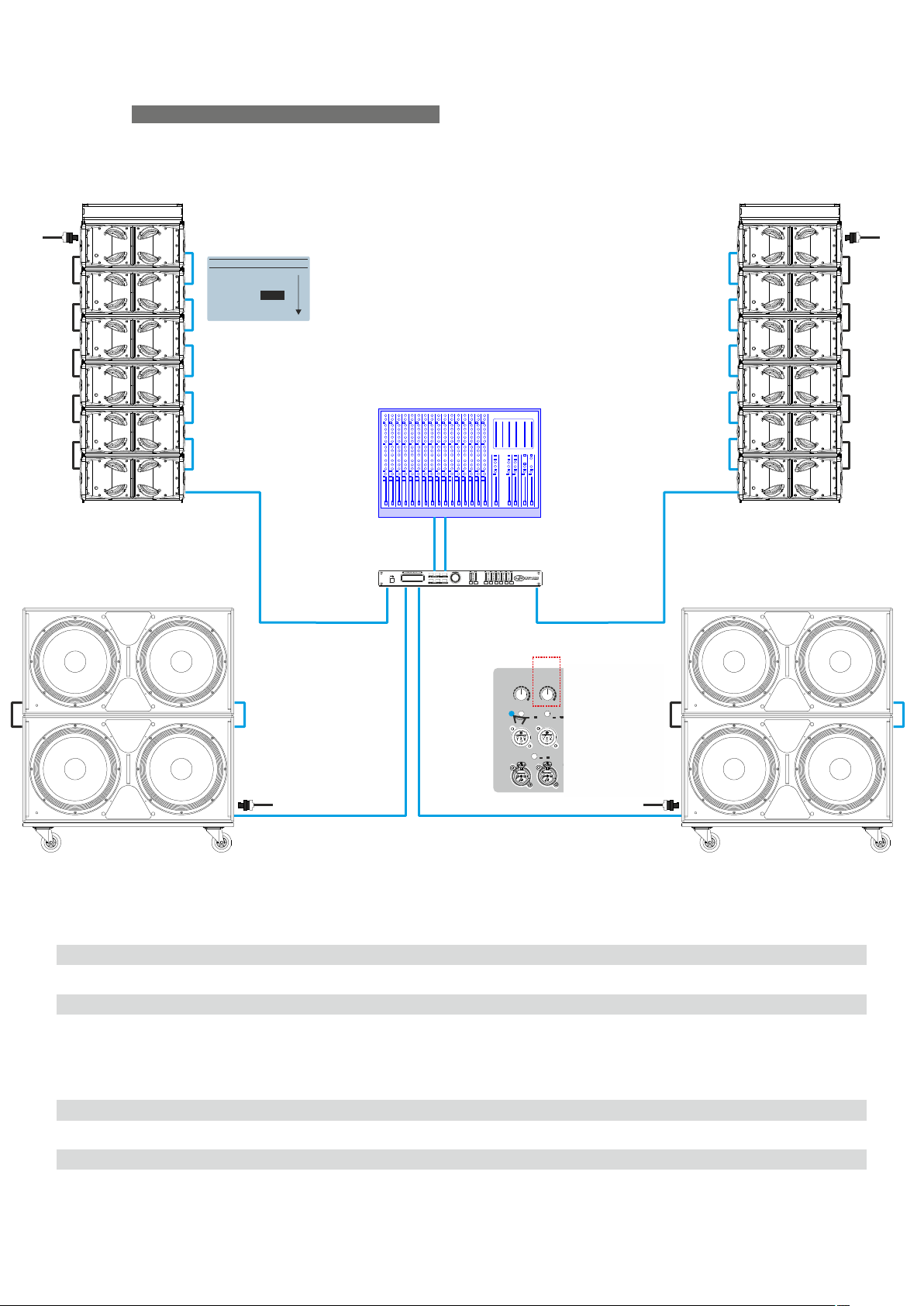
CONFIGURATIONS (cont’d)
AX-EV26
MAIN MENU
BACK
No.of U: <6U>
DownFill: off
12 x EVENT-26A + 4 x EVENT-218A
DSP-226 2 IN x 6 OUT Digital Signal Processor
Speaker cabling
SC-05 0.5m XL R microphone signal balanced cable
SC-1 1m XL R microphone signal balanced cable
SC-20 20m XL R microphone signal balanced cable
PWCONL INK-09 0.9m powerCON “jumper“ NAC3FCB cable
Rigging frames
AX-EV26 Rigging bumper for EV ENT-26A / EVEN T-115A
Dollies
INPUT A
LPF 80Hz
LEVEL
LOW-PASS
0
80Hz
+6-oo
63Hz
POLARITY
- +
OUTPUT A OUTPUT B
SATELLITE X-OVER
HPF/THRU
LIMIT
SIGNAL
ON
100Hz
CARDIOID
OMNI CARDIOID
PRESET
R F
www.dasaudio.com
INPUT B
DAS Audio Group, S.L. (Valencia)
MADE IN SPAIN
CARDIOID
F
F
AC INPUT
115/230 V~ 50/60Hz 0W83
RFR
DO NOT EXPOSE THIS EQUIPMENT
AC OUTPUT
MAX. 3@230V / 1@115V
UNITS EVENT-121A
series
Model: EVENT-121A
F
RISK OF ELECTRIC SHOCK
DO NOT OPEN
CAUTION
TO RAIN OR MOISTURE
F
UnitsProcessors
1
10
2
4
12
2
PL-EV218S Plywood transport dolly for EV ENT-218A
PL-EV26S Steel transport dolly for EV ENT-26A
12
2
2
Manual del Usuario / event series / User’s Manual
Page 13
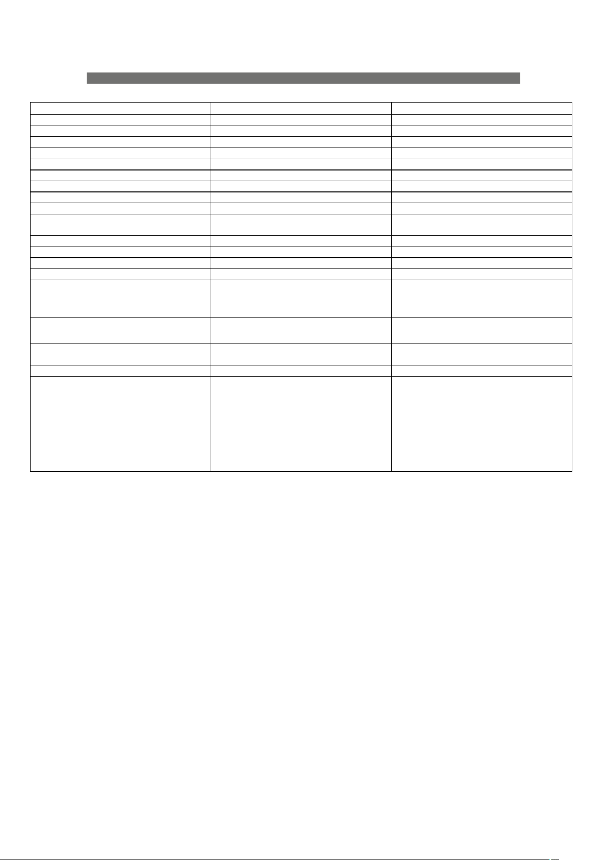
SPECIFICATIONS
EVENT-212A, EVENT-212.120A & EVENT-121A
(1). Maximum calculated Peak SPL based on sensitivity and RMS power handling.
Model
EVENT-26A EVENT-115A
Nominal LF Power Amplifier 600W peak - 300 W continuous 1200W peak - 600 W continuous
Nominal HF Power Amplifier 200W peak - 100 W continuous ---
Input Type Balanced Differential Line Balanced Differential Line
Input Impedance Line: 20 kohms Line: 20 kohms
Sensitivity Line: 6.2 V (+18 dBu) Line: 6.2 V (+18 dBu)
Frequency Range (-10 dB) 80 Hz -17 kHz 40 Hz -125 Hz
Horizontal Coverage (-6dB) 100º Nominal ---
Vertical Coverage Splay Dependent Splay Dependent
Rated Maximum Peak SPL at 1 m
(1)
131dB 131 dB
Transducers/Replacement Parts LF: 2 x 6MI/ 6MI
HF: 1 x M-60/GM-M60N
LF: 1 x 15FW4/GM-15FW4
Enclosure Geometry Trapezoidal 5º Rectangular
Enclosure Material ABS High Impact Birch Plywood
Color/Finish Black Polyurea Paint Black Polyurea Paint
Rigging System Splay Angles Integrated in box design Integrated in box design
Connectors
INPUT: 1 x Female XLR
LOOP THRU: 1 x Male XLR
AC INPUT: 1 x powerCON NAC3FCA
AC OUTPUT:1 x powerCON NAC3FCB
INPUT: 2 x Female XLR
LOOP THRU: 2 x Male XLR
AC INPUT: 1 x powerCON NAC3FCA
AC OUTPUT:1 x powerCON NAC3FCB
AC Power Requirements 115 V, 3.6A, 50 Hz/60 Hz
230 V, 1.8A, 50 Hz/60 Hz
115 V, 3.6A, 50 Hz/60 Hz
230 V, 1.8A, 50 Hz/60 Hz
Dimensions (H x W x D) 225 x 480 x 485 mm
8.9 x 18.9 x 19.1 in
481 x 485 x 770 mm
18.9 x 18.9 x 19.1 in
Weight 16.5 kg (36.3 lb) 36.8 kg (81 lb)
Accessories AX-EV26 Rigging System
AXS-EV26 Stacking Base
FUN-4-EV26 Transport Cover
FUN-6-EV26Transport Cover
PL-EV26S Stacking Dolly
JP-EV26 Joining plate
AXC-ZT
TRD-2 Tripod
TRD-7 Extensible Pole Mount
AX-EV26 Rigging System
FUN-2-EV115 Transport Cover
PL-EV115S Stacking Dolly
JP-EV26 Joining plate
TRD-7 Extensible Pole Mount
DAS Audio Group, S.L. continuously strives to enhance its products through investigation and development. All specifications are
subject to change without prior notice.
Manual del Usuario / event series / User’s Manual
13
Page 14
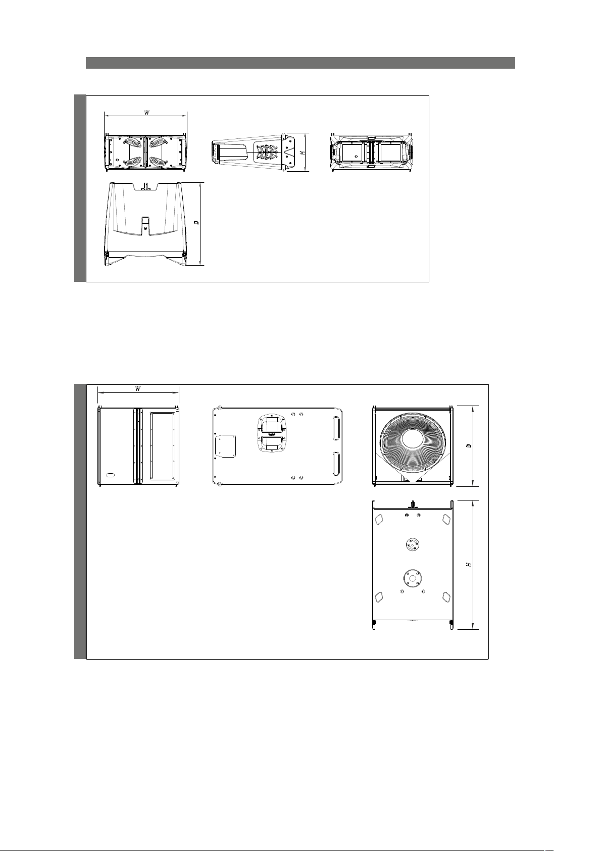
LINE DRAWIN GS
EVENT-26A
14
EVENT-115A
Manual del Usuario / event series / User’s Manual
Page 15
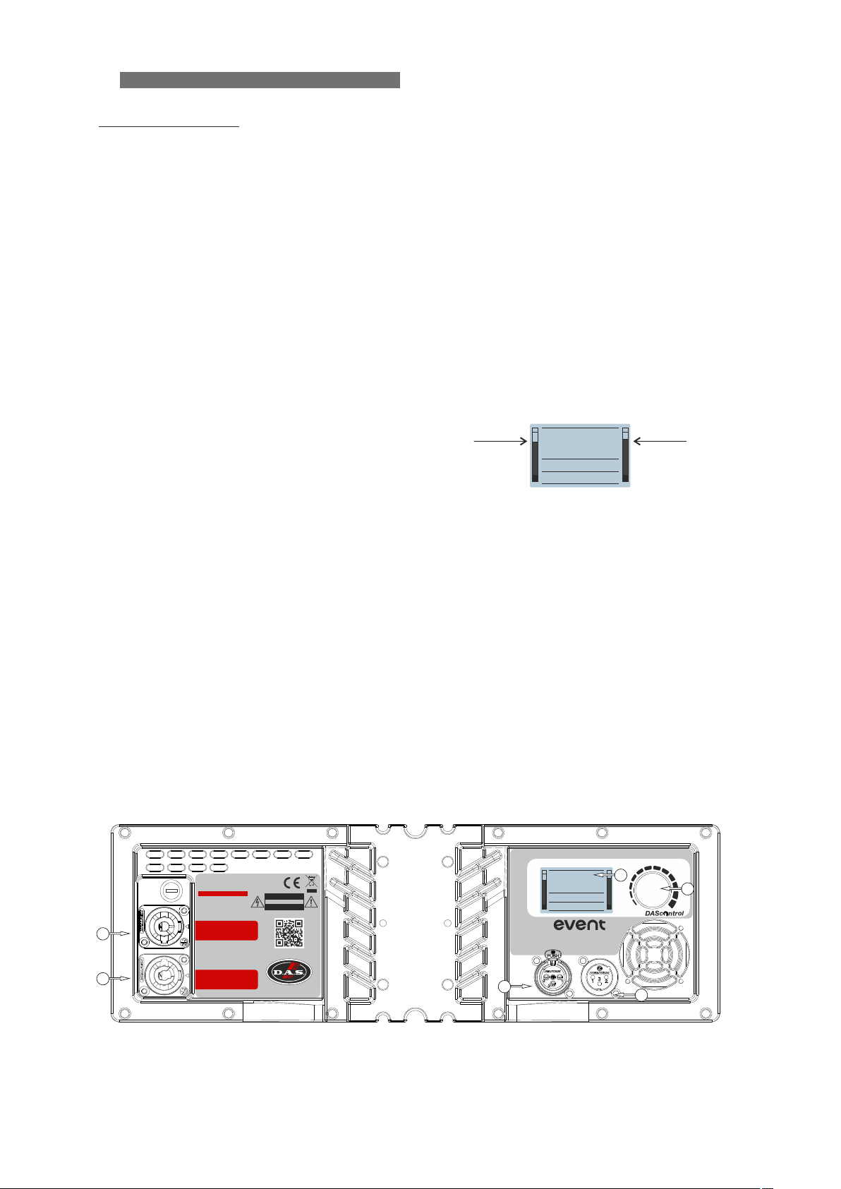
AMPLIFIERS
EVENT-26A amplifier
1) INPUT :
XLR socket-type input signal connector. This is a balanced connector just like the OUTPUT connector with the
following pin assignments:
1 or S =GND (ground) 2 or T =(+) Non inverted input 3 or R =(-) Inverted input
2) OUTPUT :
XLR-type output signal connectors for connecting several units together and sending them all the same input
signal (THRU).
3) DISPLAY:
LIMIT / INPUT CLIP :
The signal´s input level can be monitored in the LCD screen on the left meter. When the signal level is too high the
Display will show “INPUT CLIP”. Please reduce the level accordingly.
The output level with respect to the Limiter threshold can be monitored on the right meter. When the value reaches
the limiter threshold the Display will show “LIMIT” (depending on the configuration mode the Display can be
programmed to blink when the system is limiting).
SIGNAL :
The left meter indicates the presence of signal.
ON :
The Display will be illuminated when the system is on.
Input level Output level
DownFill: off
1
No.of U:
1U
DELAY: 0.0m
O
The background light of the display can be switched off permanently by selecting in the options / Dimming menu, the
“dark” preset. This option will make the Display blink (on and off) when the system reaches its limit. This option maybe
useful in theaters or similar applications in order to reduce the visual contamination.
4) ENCODER (DAScontrol) :
Use the rotary encoder to navigate for preset selection (number of units, downfill) and options (reset, dimming etc).
5) AC INPUT :
PowerCon NAC3FCA mains connector (inserted, rotated and locked for ON). Only use this equipment with an
appropriate mains cord.
6) AC OUTPUT :
PowerCon NAC3FCB connector for AC loop thru (see unit’s label)). Only use this equipment with an appropriate
mains cord.
O
PUSH FOR
Model: EVENT-26A
3
4
2
15
AUDIO MANAGEME NT
INPUT
1
No.of U:
1U
DownFill: off
DELAY: 0.0m
line array
LOOP THRU
FOR CONTINUED PROTECTION
AGAINST RISK OF FIRE REPLACE
ONLY WITH THE SAME TYPE
T3 A L 250V FUSE
AC OUTPUT
6
5
MAX. 16@230V / 8@115V
UNITS EVENT-26A
Made in Spain
AC INPUT
115/230 V~ 50/60Hz 180W
RISK OF ELECTRIC SHOCK
DO NOT OPEN
CAUTION
DO NOT EXPOSE THIS EQUIPMENT
TO RAIN OR MOISTURE
www.dasaudio.com
DAS Audio Group, S.L.
Valencia)(
1
Manual del Usuario / event series / User’s Manual
Page 16
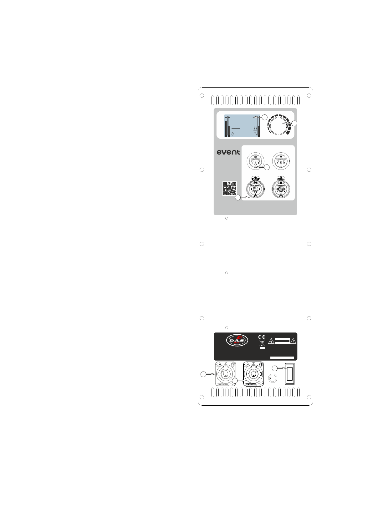
EVENT-115A amplifier
1) INPUT :
1/4” Jack+ X L R combined socket-type input signal
connector. This is a balanced connector just like the OUTPUT
connector with the following pin assignments:
1 or S =GND (ground) 2 or T =(+) Non inverted input 3
or R =(-) Inverted input
2) OUTPUT :
A and B, XLR-type output signal connectors for connecting
several units together and sending them all the same input
signal (THRU).
3) DISPLAY:
AUDIO MANAGEM ENT
loud Top
1 2
line array
0 dB
0.0m
3
O
OUTPUT 1
VOLUME
4
PUSH FOR DSP
OUTPUT 2
LIMIT / INPUT CLIP :
The signal´s input level can be monitored in the LCD
screen on the left meters, channels 1 and 2. When the signal
level is too high the Display will show “INPUT CLIP”. Please
reduce the level accordingly.
The output level with respect to the Limiter threshold can
be monitored on the right meter. When the value reaches the
limiter threshold the Display will show “LIMIT” (depending on
the configuration mode the Display can be programmed to
blink when the system is limiting).
SIGNAL :
The left meter indicates the presence of signal.
ON :
The Display will be illuminated when the system is on.
The background light of the display can be switched off
permanently by selecting in the options / Dimming menu, the
“dark” preset. This option will make the Display blink (on and
off) when the system reaches its limit. This option maybe
useful in theaters or similar applications in order to reduce the
visual contamination.
4) ENCODER (DAScontrol) :
Use the rotary encoder to navigate for preset selection (Low
Pass Filter, deep-loud etc) and options (reset, dimming etc).
5) AC INPUT :
PowerCon NAC3FCA mains connector (inserted, rotated
and locked for ON). Only use this equipment with an
appropriate mains cord.
6) AC OUTPUT :
5
www.dasaudio.com
1
DAS Audio Group, S.L. (Valencia)
AC INPUT
115/230 V~ 50/60Hz
325W
6
INPUT 1
Made in Spain
AC OUTPUT
MAX. 10@230V / 4@115V
UNITS EVENT-115A
2
DO NOT EXPOSE THIS EQUIPMENT
Model: EVENT-115A
FOR CONTINUED PROTECTION
AGAINST RISK OF FIRE REPLACE
ONLY WITH THE SAME TYPE
T5 A L 250V FUSE
7
RISK OF ELECTRIC SHOCK
DO NOT OPEN
CAUTION
TO RAIN OR MOISTURE
INPUT 2
PowerCon NAC3FCB connector for AC loop thru (see
unit’s label)). Only use this equipment with an appropriate
mains cord.
7) POWER :
‘Mains power ON/OFF switch. To disconnect the device
the user should use the mains plug.
16
Manual del Usuario / event series / User’s Manual
Page 17
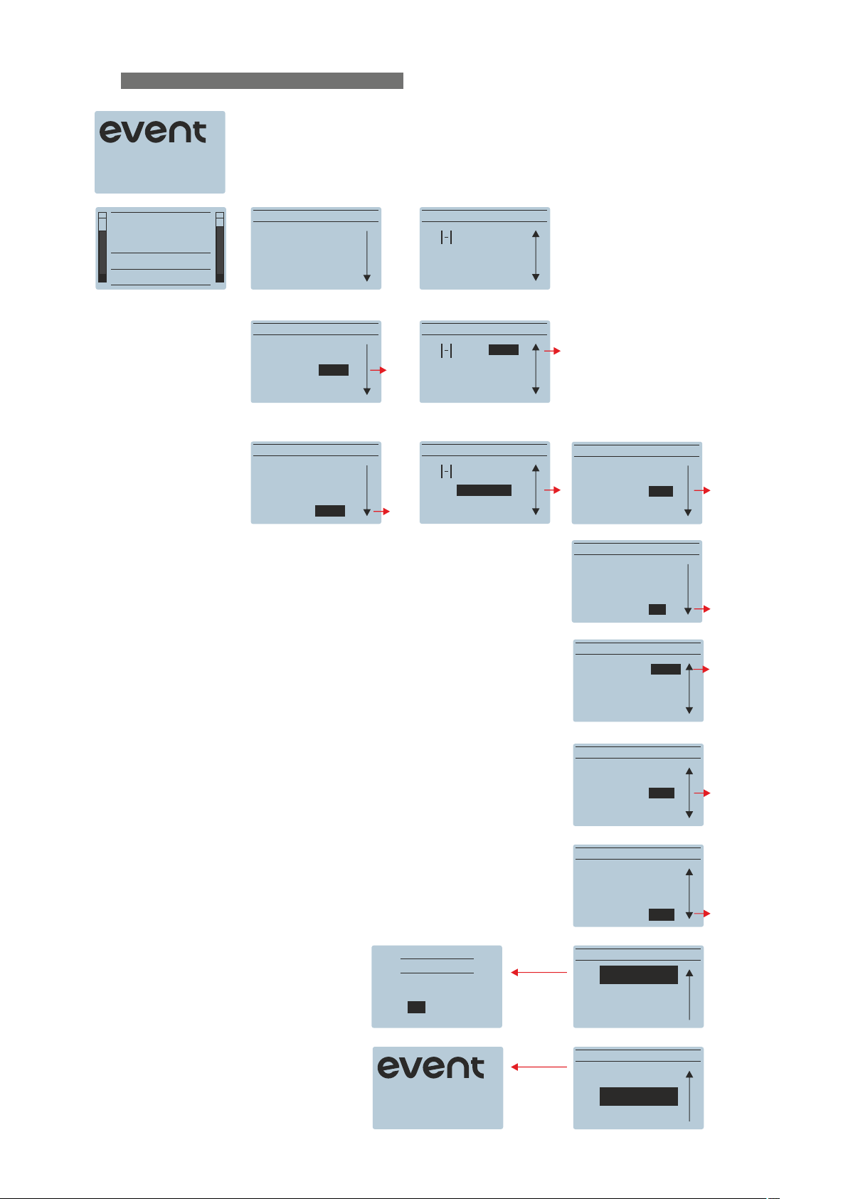
DAScontrol and display navigation
26A
FW v1.19 2910
DownFill: off
1
No.of U:
1U
DELAY: 0.0m
MAIN MENU MAIN MENU
BACK
No.of U: 1U
O
DownFill: off
MAIN MENU
BACK
No.of U: <6U>
DownFill: off
MAIN MENU
BACK
No.of U: 6U
DownFill: <ON
1U
2U
4U
6U
8U
12U
ON
off
Delay: 0.0m
OPTIONS
BACK
MAIN MENU
Delay: 0.0m
OPTIONS
BACK
MAIN MENU
Delay: 0.0m
OPTIONS
BACK
0.0m
9.9m
OPTIONS MENU
CONTRAST: 0
OPTIONS MENU
CONTRAST: 0
BACK
BRIGHT: +10
BACK
BRIGHT: +10
+10
-10
+10
-10
off: the background light is always on.
on: the background light is lowered when the system doesn´t
Limit. when Limit is reached the background light increases its
luminosity.
dark: the bakcground light is always off.
RESET DEVICE
Are you sure?
YES
NO
26A
FW v1.19 2910
Manual del Usuario / event series / User’s Manual
OPTIONS MENU
DIMMING: <on>
MENU LOCK: off
DLY UNITS: m
OPTIONS MENU
DIMMING: on
MENU LOCK: off>
DLY UNITS: m
OPTIONS MENU
DIMMING: on
MENU LOCK: off
DLY UNITS: m>
OPTIONS MENU
RESET DEVICE
INFORMATION
BACK
OPTIONS MENU
RESET DEVICE
INFORMATION
BACK
off
on
dark
off
on
pw292
m
ft
17
Page 18
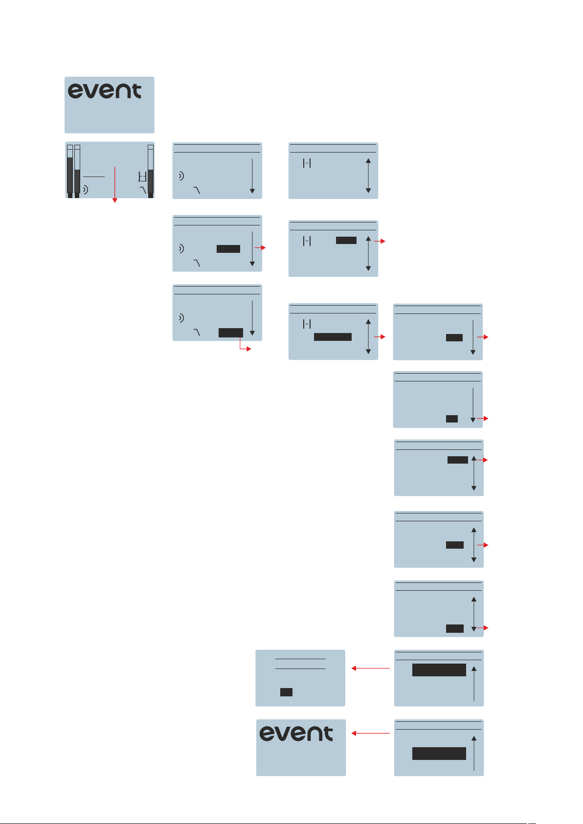
115A
FW v1.1 2905
0 dB
0.0m
loud Top
1 2
Level control: can be adjusted
between MUTE (-60dB) and 0dB
Top: recommended when
using the subwoofer with
EVENT-26A
MAIN MENU
BACK
PRESET: loud
O
LPF: Top
MAIN MENU
BACK
PRESET: loud>
LPF: Top
MAIN MENU
BACK
PRESET: loud
LPF: <Top>
loud
deep
63Hz
Top
100Hz
MAIN MENU
Delay: 0.0m
OPTIONS
BACK
MAIN MENU
Delay: 0.0m
OPTIONS
BACK
MAIN MENU
Delay: 0.0m
OPTIONS
BACK
0.0m
9.9m
OPTIONS MENU
CONTRAST: 0
OPTIONS MENU
CONTRAST: 0
BACK
BRIGHT: +10
BACK
BRIGHT: +10
+10
-10
+10
-10
18
off: the background light is always on.
on: the background light is lowered when the system doesn´t
Limit. when Limit is reached the background light increases its
luminosity.
dark: the bakcground light is always off.
RESET DEVICE
Are you sure?
YES
NO
115A
FW v1.1 2905
Manual del Usuario / event series / User’s Manual
OPTIONS MENU
DIMMING: <on>
MENU LOCK: off
DLY UNITS: m
OPTIONS MENU
DIMMING: on
MENU LOCK: off>
DLY UNITS: m
OPTIONS MENU
DIMMING: on
MENU LOCK: off
DLY UNITS: m>
OPTIONS MENU
RESET DEVICE
INFORMATION
BACK
OPTIONS MENU
RESET DEVICE
INFORMATION
BACK
off
on
dark
off
on
pw292
m
ft
Page 19
RECOMMENDATIONS OF USE
ON / OFF
A sound system should be switched on
sequentially. Switch on the self-powered units last
in your sound system (switch on the subwoofer
before the mid-high system). Switch on the sound
sources such as CD players or turntables, then the
mixer, then the processors, and finally the selfpowered unit. If you have several units, it is
recommended that you switch them on sequentially
one at a time.
Follow the inverse order when switching off,
turning self-powered units off before any other
element in the sound system.
Disconnect the device by removing the mains
connector from the mains socket. The mains
connector and mains socket must always be freely
accessible and never covered or blocked in any
way.
The models use a power cable equipped with a
Neutrik PowerCon NC3FCA connector. Power can
be daisy chained via the NC3FCB output connector
(see details on product label).
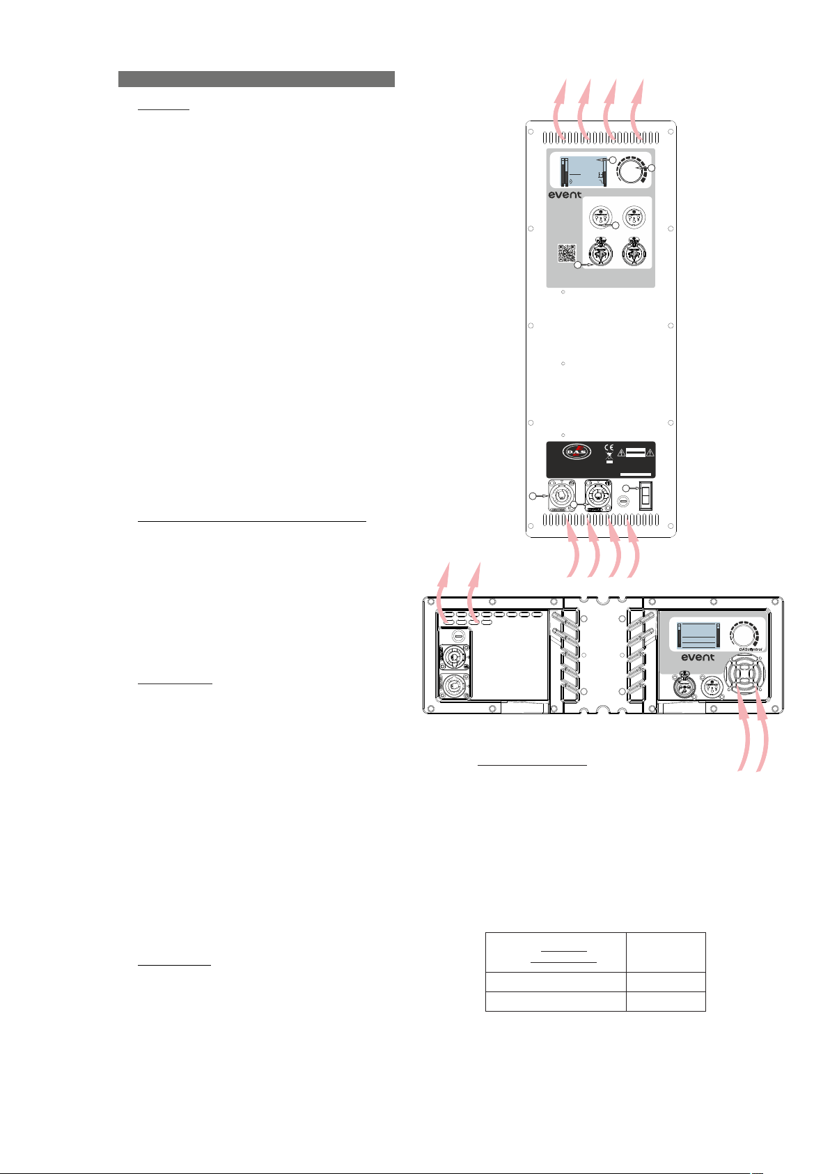
Air circulates from the bottom to the top of the amplifier.
0.0m
Made in Spain
O
OUTPUT 1
INPUT 1
3
2
VOLUME
4
PUSH FOR DSP
OUTPUT 2
INPUT 2
AUDIO MANAGEMENT
0 dB
loud Top
1 2
line array
www.dasaudio.com
1
Heatsink of EVE NT-115A amplifier
IMPORTANT: Do not disconnect the unit while
in use.
Ensure that the device is disconnected from the
mains by observing that the display is turned off.
Overload indicator (LIMIT / INPUT CLIP)
This device has an indicator (LIMIT / INPUT
CLIP) that it is shown on the display when the signal
level is excessive.
The indicator should not be lit continuously. This
distorts the signal (quickly fatiguing your ears) and
may damage the speakers. Therefore, it is
recommended that you never work with these two
messages engaged; at most it should blink only
occasionally.
Equalisation
It is recommended the use of a computer based
dual-channel FFT platform to view the frequency
content of signals or measure the response of the
entire electro-acoustic system, all to better make
informed decisions about the deployment and
operation of these systems.
The unit does not need extreme settings of
equalisation to produce quality sound, just select
the parameter “number of units” in the amplifier that
corresponds to the amount of systems used and
you will achieve a very good and balanced starting
point before measuring and tunning the system.
Avoid high levels of gain on the equalisers. Gain
values above +6 dB on a console’s / processor´s
EQ are not recommended.
Overheating
This equipment does not normally overheat
during normal conditions of use. When overheating
occurs, the FAN (EVENT-26A) will automatically
start working reducing the temperature of the unit.
Make sure that the rain protectors are properly
separated from the amplifier´s back plate in order to
not block the air flux thru the fan.
RISK OF ELECTRIC SHOCK
DO NOT OPEN
CAUTION
DO NOT EXPOSE THIS EQUIPMENT
TO RAIN OR MOISTURE
Model: EVENT-115A
FOR CONTINUED PROTECTION
AGAINST RISK OF FIRE REPLACE
ONLY WITH THE SAME TYPE
T5 A L 250V FUSE
7
AUDIO MANAGEMENT
1
INPUT
No.of U:
1U
DownFill: off
DELAY: 0.0m
line array
LOOP THRU
O
PUSH FOR
5
DAS Audio Group, S.L. (Valencia)
AC INPUT
115/230 V~ 50/60Hz
325W
AC OUTPUT
MAX. 10@230V / 4@115V
UNITS EVENT-115A
6
Heatsink of EVE NT-26A amplifier
Low mains voltage
If mains voltage falls below the shutdown
voltage for the unit, it will stop playing, typically this
value would be below 90Volts. When acceptable
levels are regained, the unit will switch back on
automatically.
Therefore the current consumed by a 115V
version is double the 230V version to achieve the
same acoustic power level.
Pink Noise
Mains 230 Vrms
EVENT-26A
EVENT-115A
1/3 Power
0.8A
1.4A
Model: EVENT-26A
Manual del Usuario / event series / User’s Manual
19
Page 20
Troubleshooting
PROBLEM
CAUSE
SOLUTION
No s o u nd f r o m t h e u n i t . Th e
DISPLAY does not light up.
Full power cannot be obtained. The
LIMIT message is never displayed.
So und i s dist orte d. T h e L I M IT
message is not on, or only lights up
occasionally but INPUT Clip is on.
Sound is distorted and very loud and
LIMIT message is shown.
Hu m or buz z when a m ixe r i s
connected to the unit.
1 - No power to the unit.
2 - Defective cable / connector.
3 - Defective amplifier.
1 - The signal source does not have a
hot enough output.
2 - There could be some
equalisations, filters or
compressors applied in other
devices (console, processor).
Th e m i xer or sign a l s ource is
distorting or it has excessive level.
The system is overloaded and has
reached maximum power.
1.– The console probably has unbalanced outputs. You may be using
a n i n co rr e ct u n -b a la n ce d t o
balanced cable.
2.– The mixer and the powered
speaker are not plugged into the
same mains outlet.
3.– The audio signal cable is too long
or too close to an AC cable
1 - Check all the connections and
the power distro.
2 - Check that the cable and
connector are working properly.
3 - Contact with the dealer/tech
support in the area.
1 - If you use a mixer, be sure to use
the balanced output if you have it.
Use a professional mixer or signal
source with more output level.
2 - Double check the signal path and
erase all Eqs, compressors applied.
Turn mixer channel gains down.
Check that none of y our signal
sources are distorting.
Turn down the mixer's output.
1.– Read the appendix of this manual
to make a correct un-balanced to
balanced cable.
2.– Connect the mixer and the unit to
the same mains outlet.
3.– Use a cable that is as short as
possible and/or move the audio
si g nal cabl e a w ay from mai n s
cables.
Hum or buzz when using lighting
controls in the same building.
The DI SPL AY does not light up
when t h e ma in s c o n n e c t or is
connected and the unit is switched to
ON.
1.– The audio signal cable is too long
or too close to the lighting cable.
2.– On a sound system with threephase AC, the lighting equipment
and the UNIT are connected to the
same phase.
1.– Bad or loose AC connection to
the UNIT or the mains outlet.
2 – Faulty AC cable.
3 – Blown Fuse.
4 - The mains voltage is out of range.
1.– Move the audio signal cable
away from lighting cables. Try to find
out at what point the noise is leaking
into the system.
2.– Connect the sound system to a
different phase than the lights. You
may need the help of an electrician.
1.– Check your connections.
2.– Check the cables, connectors
and AC power with a suitable mains
tester.
3.- Replac e th e bl own fuse for
another of the same type and size.
4.- If the multimeter determines that
the mains voltage is out the range,
you may need the assistance of an
electrician to find an appropriate
solution.
20
Manual del Usuario / event series / User’s Manual
Page 21
RIGGING SYSTEM
Warning
This manual offers all the necessary
information for flying or stacking EVENT Line
Array series systems of DAS Audio. This
information is illustrated with drawings and
required safety precautions.
To any operations related to flying a
system, read the present document first and
act on the warnings and advice given. The
goal is to allow the user to become familiar
with the mechanical elements required to fly
the acoustic system, as well as the safety
measures to be taken during set-up and
teardown.
Only experienced installers with adequate
knowledge of the equipment and local safety
regulations should fly speaker boxes. It is the
user´s responsibility to ensure that the
systems to be flown (including flying
accessories) comply with state and local
regulations.
The working load limits in this manual are
th e re sults of tests b y in dependent
laboratories. It is the user´s responsibility to
follow and comply with safety factors,
resistance values, periodical supervisions
and warnings given in this manual. Product
improvement by means of research and
development is on going at DAS Audio Group,
S.L. Specifications are subject to change
without notice.
It is common practice to apply 5:1 safety
factors for enclosures and static elements.
For slings and elements exposed to material
fatigue due to friction and load variation the
following ratios must be met; 5:1 for steel
clable slings; 4:1 for steel chain slings and 7:1
for polyester slings. Thus, an element with a
breaking load limit of 1000 kg may be statically
loaded with 200 kg (5:1 safety factor) and
dynamically loaded with 142 kg (7:1 safety
factor).
When a system is flying, the working load
must be lower than the resistance of each
individual flying point in the enclosure, as well
as each box. Hanging hardware should be
regularly inspected and suspect units
replaced if in doubt. This is important to avoid
injury and absolutely no risks should be taken
in this respect. It is highly recommended that
yo u im pl em e n t an in s p e c ti on a nd
maintenance program on flying elements,
including reports to be filled out by the
personnel that will carry out the inspections.
Local regulations may exist that, in case of
accident, may require you to prevent evidence
of inspection reports and corrective actions
after defects were found.
Absolutely no risks should be taken with
regards to public safety.
When flying enclosures from ceiling support
structures, extreme care should be taken to
assure the load bearing capabilities of the
structures so that the installation is absolutely
safe. Do not fly enclosures from unsafe
structures. Consult a certified professional if
needed. All flying accessories that are not
supplied by DAS Audio are the user´s
responsibility. Use at your own risk.
Manual del Usuario / event series / User’s Manual
21
Page 22
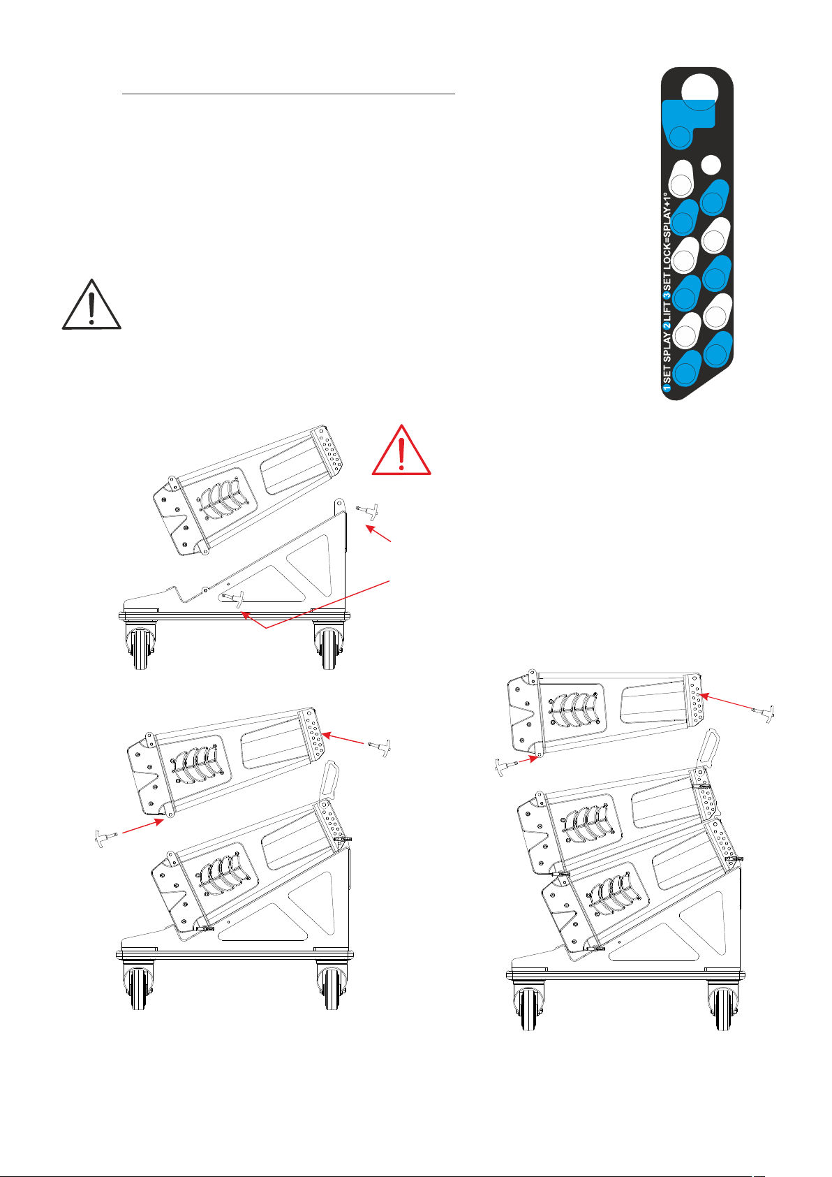
4 or 6 units mounting on a PL-EV26S flatbed dolly
Groups of four or six units are easy to transport by
truck as we will see in this manual.
Once the packaging is removed, you can see four
security locking pins on the rear enclosure´s rigging
system. These pins are going to be used to stack the
cabinets; always use the pins of the unit to attach the
one that is going to be located above it. The rigging
system of the E V E NT-26A employs a 3 point
attaching system. Use two of the pins in the front left
and right structures and the other two in the rear one.
The PL-EV26S includes 3 locking pins to stack the
first unit.
Warning: For transport, introduce the pin in
hole 1º at “Rear Link"in the first EVENT-26A
"Rear Link"
at 1º
The next figure shows the detail
of the label located at the rear
rigging structure of the EVENT26A.
Splay angles vary form 0º to 10º in
steps of 1º.
To secure (lock the movement)
the s y s te m s when fl y i ng o r
st acking them, t wo pins are
needed at the rear. One must be
introduced in the “splay” angle
ho le , a n d t he o th e r i n t he
“splay+1º” hole.
Fig.3
PIN
HOLDER
10+1
10
8
6
4
2
0
9
7
5
3
1
Fig.1
Use 3 pins (PIN-6)
of t h e P L- E V 2 6 S
2 at the front, one on
each side
Use 4 pins (PIN-6)
of the bottom EVENT-26A
2 at the front and 2 at the rear
link
W h en t ra ns p or t in g th e s y st e m s i s
recommended to insert one of the pins in the
10º splay angle at the rear. By doing this the
cabinets wouldn´t be able to get separted from
the rear.
set splay
22
Fig.2
Fig.4
Manual del Usuario / event series / User’s Manual
Page 23
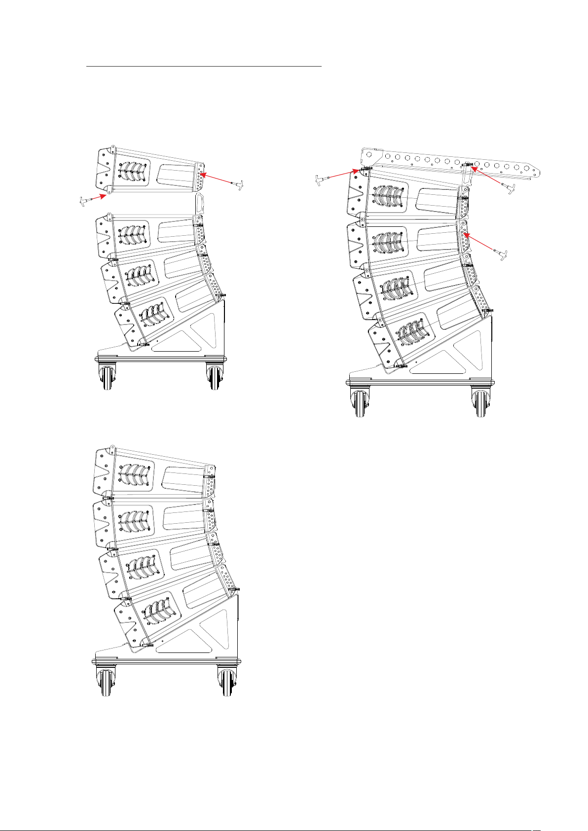
4 or 6 units mounting on a PL-EV26S flatbed dolly
Repeat the process shown in the previous figures with
the rest of the cabinets. In this case, the set up of 4
units is shown.
Finally, the rigging bumper, AX-EV26 can be attached
to the top cabinet using its available pins. insert two
pins at the front and one at the rear. keep the extra pin
stored in the cabinet.
set splay
Fig.5
At his point the cover for 4 units could be placed to
protect them during transportation:
Fig.7
Fig.6
Manual del Usuario / event series / User’s Manual
23
Page 24
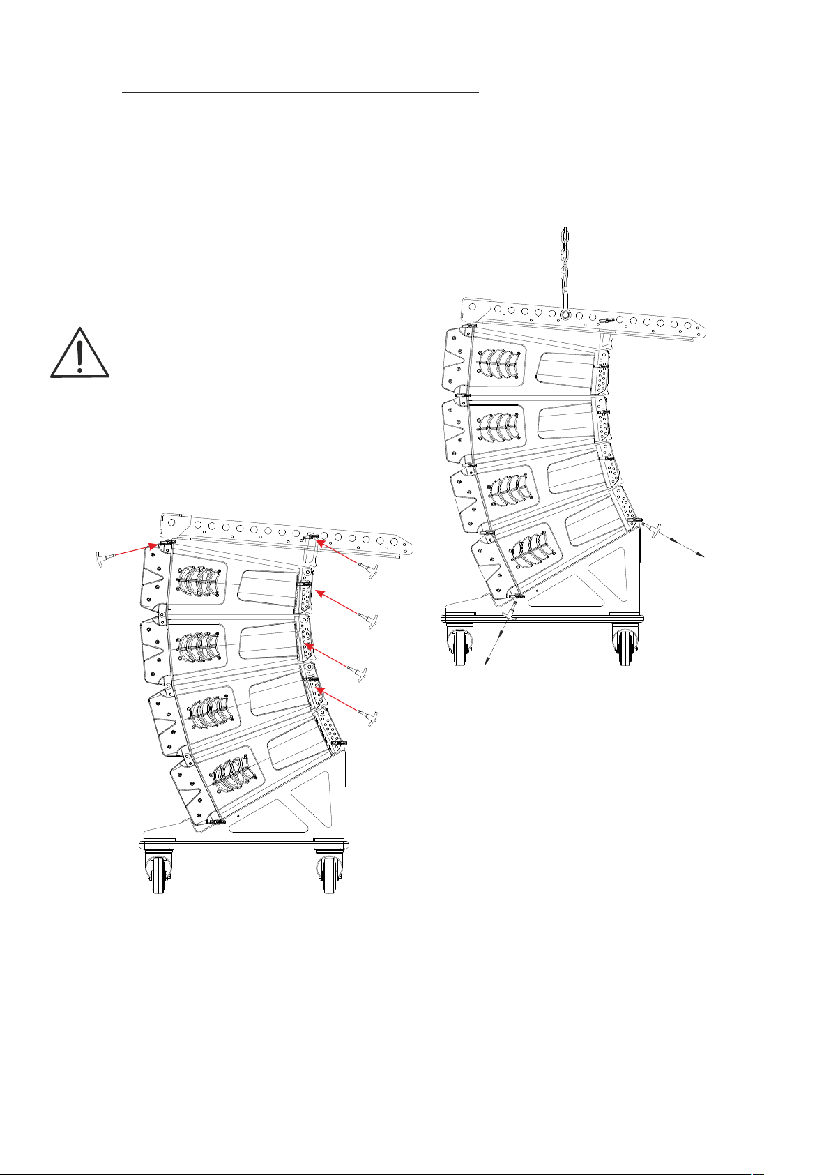
Array mounting of groups of 4 units on a flatbed dolly
Groups of to 4 or 6 units are easy to transport by truck.
We will see in this section the assembly of an array system with groups of four units previously placed
on the PL-EV26S dollies.
Fix the shackle in the pin point hole of the AX-EV26
determinated by the Ease Focus 3 project and
The first group with 4 units will be the superior
group, that is to say, the group where we will install
the AX-EV26.
To assembly the AX-EV26, first, remove the
cover from the stack and use the pins of the top
cabinet.
Insert the pins of the top cabinet in the dedicated
holes of the AX-EV26, as shown in the figure 8 (3
pins are needed).
Next step would be running an Ease Focus
simulation in order to know the different splay
angles between the units and the pick up position.
(pin point of the central bar).
Before attaching the chain hoist to the AX-EV26,
the user should be able to vary the splay angles
between units and modify them accordingly to the
Ease Focus 3 simulation.
remove the pins that attach the bottom cabinet to
the dolly before lifting the system.
set splay angles
Fig.8
Set the splay angles between the units
accordingly to the Ease Focus Project. In this
case 0º, 2º and 4º.
remove pins
from the dolly
Fig.9
Warning: Verify the correct installation of
the security pins. These pins will support the
inferior load.
24
Manual del Usuario / event series / User’s Manual
Page 25
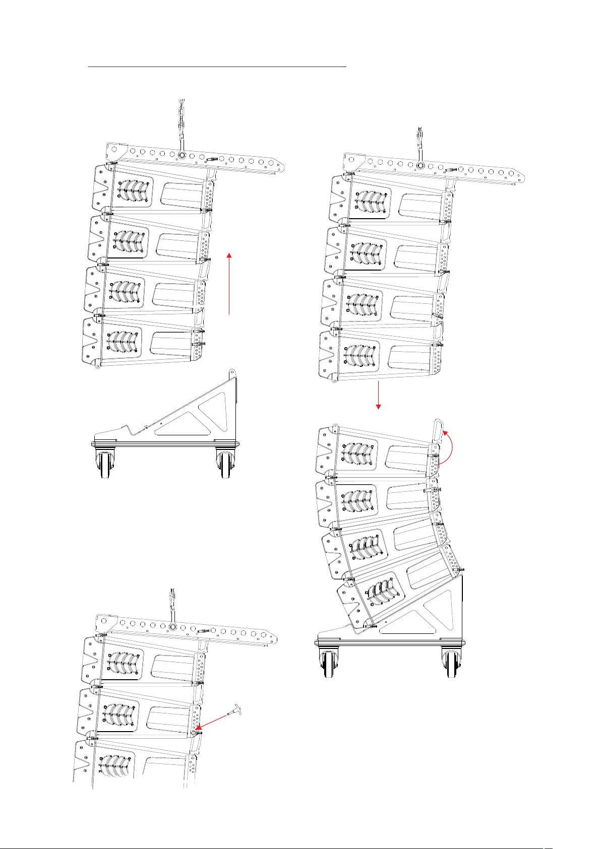
Array mounting of groups of 4 units on a flatbed dolly
Rise the system and splay angles between
cabient will be set automatically:
Raise the 4 units
Repeat the process with the second dolly.
Lower the first four units, set splay angle in the ones
stacked on the dolly, attach the two groups and rise
it. In the sample shown only three pins per cabinet
are used:
0º
1º
4º
Fig.10
NOTE: To rig the system the simplest approach is
using three pins (two at the front and one at the
rear). With this method the splay angle between
units is set automatically while the cabinets are
lifted up.
If the user needs to lock the splay angle between
the units, an extra pin (pin number 4), has to be
inserted in the rear structure in hole named
“splay+1º”.
lower the 4 units
set splay angles
Fig.11
Splay+1º will be 2º hole
1º --> this is the actual splay angle
Manual del Usuario / event series / User’s Manual
25
Page 26
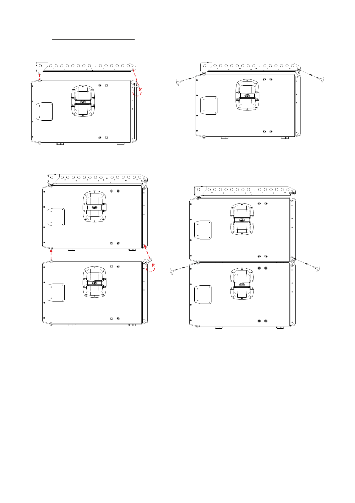
EVENT-115A Array mounting
Fig.12 Fig.13
26
Fig.14 Fig.15
Manual del Usuario / event series / User’s Manual
Page 27
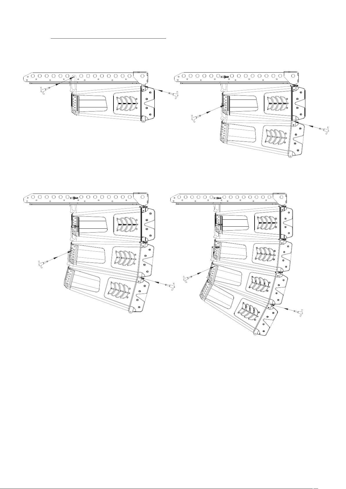
EVENT-26A Array mounting “one by one”
Fig.16 Fig.17
set splay
set splay
set splay
Fig.18 Fig.19
Manual del Usuario / event series / User’s Manual
27
Page 28
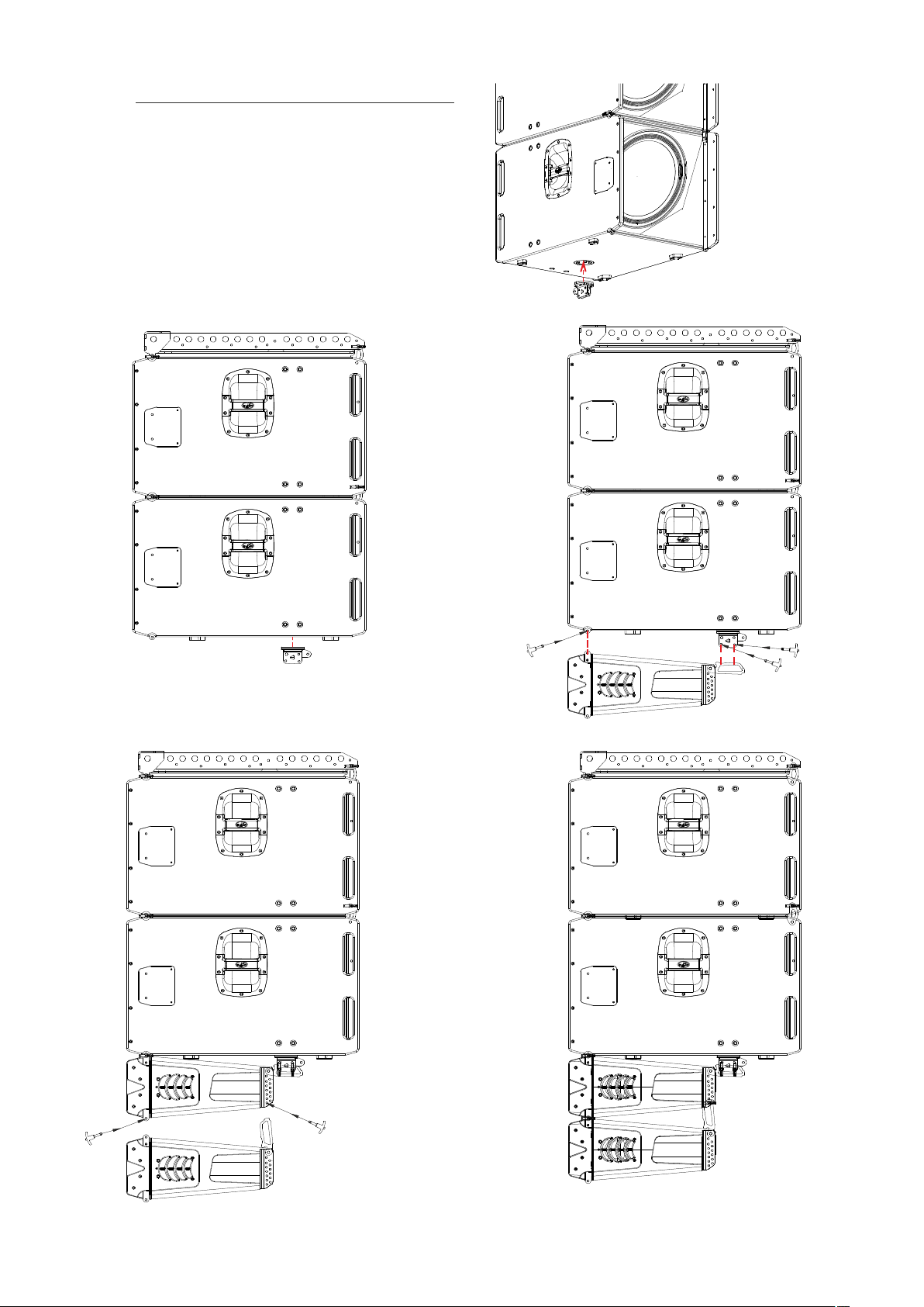
EVENT-115A + EVENT-26A Array mounting
First step will be assembling the subwoofers with
the AX-E V26. follow the process shown on
previous pages.
Next step, before hanging the EVENT-26A units is
to fix to the bottom EVENT-115A the joining plate
JP-EV26.
Fig.21
JP-EV26
Fig.20
Two pins!!
Fig.22
28
set splay
Fig.24Fig.23
Manual del Usuario / event series / User’s Manual
Page 29
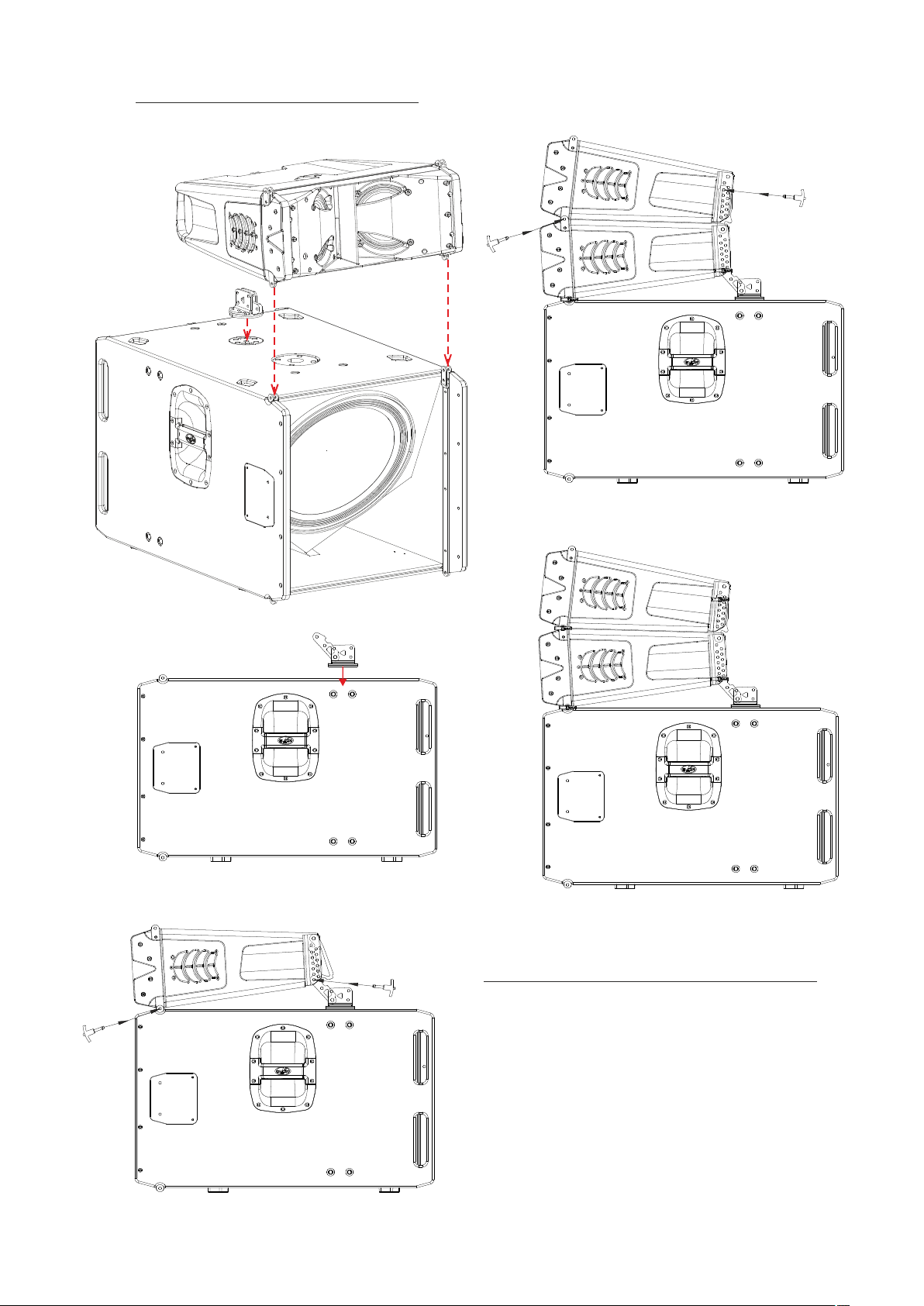
Stacking EVENT-26A on EVENT-115A
JP-EV26 joining plate is needed to stack the
systems.
in this case
splay angle = -3º
Fig.28
Fig.25
Fig.26
set splay angle
Fig.29
Angle between first EVENT-26A and EVENT-115A:
Cam link Hole - real splay angle
9º= +4º
8º= +4º
7º= +2º
6º= +2º
5º= 0º
4º= 0º
3º= -2º
2º= -2º
1º= -3º
0º= -3º
Fig.27
Manual del Usuario / event series / User’s Manual
29
Page 30
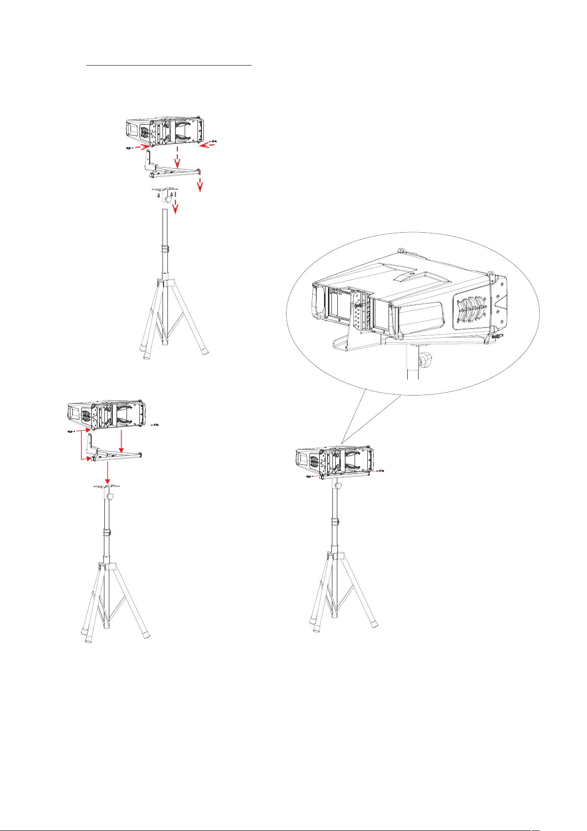
Stacking EVENT-26A on AXS-EV26
When using the AXS-EV26 to stack the system on
a tripod TRD-2 or TRD-7 pole mount and AXC-ZT
accessoty is also needed.
AXS-EV26
AXC-ZT
TRD-2
Fig.30
After first step, fix the EVENT-26A to the AXS-EV26:
First, fix the AXC-ZT to the AXS-EV26
Fig.31
Rear View - Detail
Fig.32
30
Manual del Usuario / event series / User’s Manual
Page 31
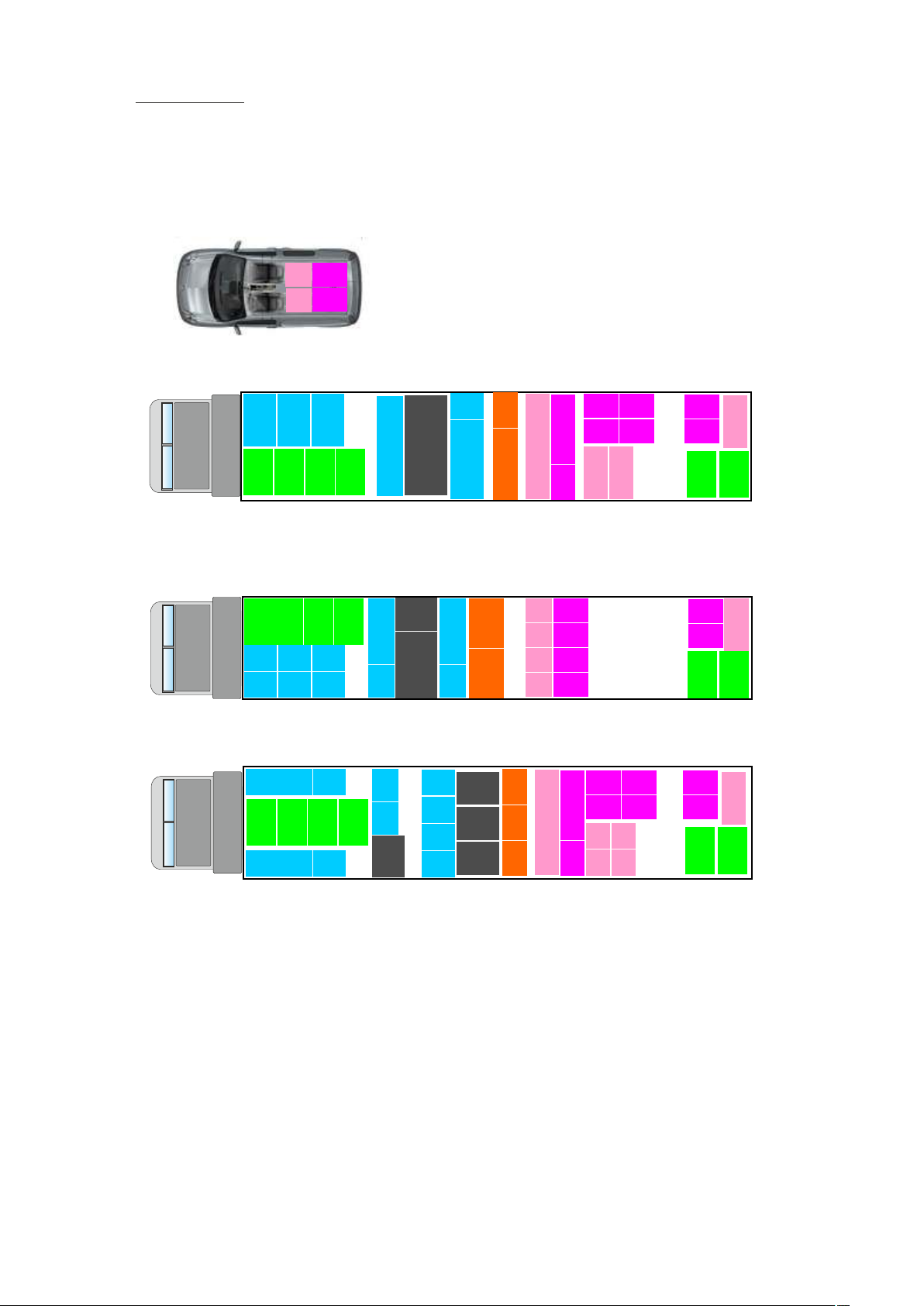
Transportation
As a compact system, 8 tops and 4 subs can be
transported in a small van:
Note: EVENT-208A/210A/218A/121A EVENT-26A and EVENT-115A (EV-26A & EV-115A in the images)
4 x
2 x
EV-26A
EV-115A
4 x
2 x
EV-26A
EV-115A
€uro truck
2 x
event
208A
event
208A
event
218A
event
208A
event
208A
event
218A
event
208A
event
208A
218A
event
218A
event
208A
event
208A
event
208A
event
event 121A
event 121A
event 121A
event
208A
event
208A
event
208A
event
208A
event
event
event
210A
210A
210A
4 x
4 x
4 x
4 x
EV-26A
EV-26A
EV-26A
EV-26A
2 x
EV-115A
2 x
EV-115A
2 x
EV-115A
EV-115A
2 x
EV-115A
4 x
EV-26A
4 x
EV-26A
2 x
EV-115A
2 x
EV-115A
4 x
EV-26A
4 x
EV-26A
2 x
EV-115A
2 x
EV-115A
event
218A
4 x
EV-26A
4 x
EV-26A
218A
event
243cm / 96”
American truck
event
event
208A
event
208A
event
208A
event
event
208A
218A
218A
event
event
208A
event
208A
event
208A
event
event
208A
218A
218A
218A
event
event
208A
event
208A
event
208A
event
event
208A
218A
218A
event
event
218A
208A
event
208A
event
208A
event
208A
event
208A
event
event 121A
event 121A
event 121A
event 121A
event
208A
event
208A
event
208A
event
208A
208A
event
208A
event
208A
event
event 121A
event 121A
event 121A
event
210A
event
210A
event
210A
event
210A
210A
event
event
event
EV-26A
EV-26A
EV-26A
EV-26A
210A
210A
4 x
4 x
4 x
4 x
4 x
4 x
4 x
4 x
EV-115A
EV-115A
EV-115A
EV-115A
EV-26A
EV-26A
EV-26A
EV-26A
2 x
2 x
2 x
2 x
2 x
EV-115A
2 x
EV-115A
event
218A
4 x
EV-26A
4 x
EV-26A
218A
event
228cm / 90”
2 x
2 x
EV-115A
2 x
EV-115A
4 x
EV-26A
4 x
EV-26A
EV-115A
EV-115A
4 x
EV-26A
4 x
EV-26A
2 x
2 x
EV-115A
2 x
EV-115A
2 x
EV-115A
2 x
EV-115A
2 x
EV-115A
event
218A
4 x
EV-26A
4 x
EV-26A
218A
event
251cm / 99”
Manual del Usuario / event series / User’s Manual
31
Page 32
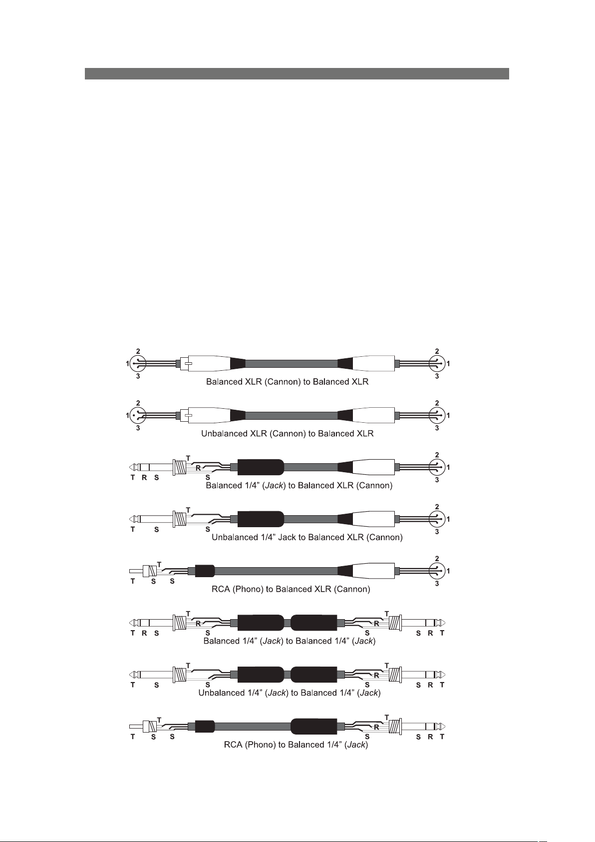
ANNE X : Line connections: unbalanced and balanced
There are two basic ways to transport an audio signal with microphone or line level:
Unbalanced line: Utilising a two conductor cable, it transports the signal as the voltage between them.
Electromagnetic interference can get added to the signal as undesired noise. Connectors that carry
unbalanced signals have two pins, such as RCA (Phono) and ¼” (6.35mm, often referred to as jack) mono. 3
pin connector such as XLR (Cannon) may also carry unbalanced signals if one of the pins is unused.
Balanced line: Utilising a three conductor cable, one of them acts as a shield against electromagnetic noise
and is the ground conductor. The other two have the same voltage with respect to the ground conductor but
with opposite signs. The noise that cannot be rejected by the shield affects both signal conductors in the same
way. At the device’s input the two signals get summed with opposite sign, so that noise is cancelled out while
the programme signal doubles in level. Most professional audio devices use balanced inputs and outputs.
Connectors that can carry balanced signal have three pins, such as XLR (Cannon) and ¼” (6.35mm) stereo.
The graphs that follow show the recommended connection with different types of connectors to balanced
processor or amplifier inputs. The connectors on the left-hand side come from a signal source, and the ones on
the right hand side go to the inputs of the processor or amplifier. Note that on the unbalanced connectors on the
left-hand side, two terminals are joined inside the connector. If hum occurs with balanced to balanced
connections, try disconnecting the sleeve (ground) on the input connector. Note that the illustrations show
what should be connected to what, but that pin locations on an actual XLR connector are different. Also, pin 2
hot is assumed on XLR connectors.
32
Manual del Usuario / event series / User’s Manual
Page 33
www.dasaudio.com
UM_EV3_01_EN
DAS Audio Group, S.L. C/. Islas Baleares, 24. 46988 Fuente del Jarro. Paterna. Valencia. España. Tel.: +34 96 134 0860
 Loading...