

66xx/67xx-W1
VDSL2/ADSL2+
Gateway Users Guide
Document Part Number: 830-04091-03
January, 2017

DASAN Zhone Solutions.
7195 Oakport Street
Oakland, CA 94621
USA
510.777.7000
www.zhone.com
info@zhone.com
COPYRIGHT ©2000-2016 DASAN Zhone Solutions, Inc. All rights reserved.
This publication is protected by copyright law. No part of this publication may be copied
or distributed, transmitted, transcribed, stored in a retrieval system, or translated into any
human or computer language in any form or by any means, electronic, mechanical,
magnetic, manual or otherwise, or disclosed to third parties without the express written
permission from DASAN Zhone Solutions, Inc.
Bitstorm, EtherXtend, IMACS, MALC, MXK, Raptor, SLMS, Z-Edge, Zhone, ZMS, zNID
and the Zhone logo are trademarks of DASAN Zhone Solutions, Inc.
DASAN Zhone Solutions, Inc makes no representation or warranties with respect to the
contents hereof and specifically disclaim any implied warranties of merchantability, non
infringement, or fitness for a particular purpose. Further, DASAN Zhone Solutions, Inc
reserves the right to revise this publication and to make changes from time to time in the
contents hereof without obligation of DASAN Zhone Solutions, Inc to notify any person of
such revision or changes.
This product may contain copyrighted software that is licensed under the GNU General
Public License (“GPL”), a copy of which is available at www.gnu.org/licenses. You may
obtain a copy of such software, in source code form, from DASAN Zhone Solutions, Inc
for a period of three years after our last shipment of the product by following the
instructions at www.zhone.com/gplinfo
.
In 2016 Zhone Technologies, Inc merged with DASAN Networks, Inc to form DASAN
Zhone Solutions, Inc..
66xx/67xx Router Users Guide 2

Important Safety Instructions
1. Read and follow all warning notices and instructions marked on the product or included
in the manual.
2. Slots and openings in the housing are provided for ventilation. To ensure reliable
operation of the product and to protect it from overheating, these slots and openings
must not be blocked or covered.
3. Do not allow anything to rest on the power cord and do not locate the product where
persons will walk on the power cord.
4. Do not attempt to service this product yourself, as opening or removing covers may
expose you to dangerous high voltage points or other risks. Refer all servicing to
qualified service personnel.
5. General purpose cables are used with this product for connection to the network.
Special cables, which may be required by the regulatory inspection authority for the
installation site, are the responsibility of the customer. Use a UL Listed, CSA certified,
minimum No. 24 AWG line cord for connection to the Digital Subscriber Line (DSL)
network.
6. When installed in the final configuration, the product must comply with the applicable
Safety Standards and regulatory requirements of the country in which it is installed. If
necessary, consult with the appropriate regulatory agencies and inspection authorities
to ensure compliance.
7. A rare phenomenon can create a voltage potential between the earth grounds of two or
more buildings. If products installed in separate buildings are interconnected, the
voltage potential may cause a hazardous condition. Consult a qualified electrical
consultant to determine whether or not this phenomenon exists and, if necessary,
implement corrective action prior to interconnecting the products.
8. Input power to this product must be provided by one of the following: (1) a UL
Listed/CSA certified power source with a Class 2 or Limited Power Source (LPS) output
for use in North America, or (2) a certified transformer, with a Safety Extra Low Voltage
(SELV) output having a maximum of 240 VA available, for use in the country of
installation.
9. In addition, since the equipment is to be used with telecommunications circuits, take
the following precautions:
— Never install telephone wiring during a lightning storm.
— Never install telephone jacks in wet locations unless the jack is specifically
designed for wet locations.
— Never touch uninsulated telephone wires or terminals unless the telephone line has
been disconnected at the network interface.
— Use caution when installing or modifying telephone lines.
66xx/67xx Router Users Guide 3

— Avoid using a telephone (other than a cordless type) during an electrical storm.
There may be a remote risk of electric shock from lightning.
— Do not use the telephone to report a gas leak which is in the vicinity of the leak.
CE Marking
When the product is marked with the CE mark on the equipment label, a supporting
Declaration of Conformity may be downloaded from the Zhone World Wide Web site at
www.zhone.com.
FCC Statement
This equipment has been tested and found to comply with the limits for a Class B digital
device, pursuant to part 15 of the FCC Rules. These limits are designed to provide
reasonable protection against harmful interference in a residential installation. This
equipment generates, uses and can radiate radio frequency energy and, if not installed
and used in accordance with the instructions, may cause harmful interference to radio
communications. However, there is no guarantee that interference will not occur in a
particular installation. If this equipment does cause harmful interference to radio or
television reception, which can be determined by turning the equipment off and on, the
user is encouraged to try to correct the interference by one or more of the following
measures:
— Reorient or relocate the receiving antenna.
— Increase the separation between the equipment and receiver.
— Connect the equipment into an outlet on a circuit different from that to which the
receiver is connected.
— Consult the dealer or an experienced radio/TV technician for help.
FCC Radiation Exposure Statement
This device complies with FCC radiation exposure limits set forth for an uncontrolled
environment and it also complies with Part 15 of the FCC RF Rules. This equipment must
be installed and operated in accordance with provided instructions and the antenna(s)
used for this transmitter must be installed to provide a separation distance of at least 20
cm from all persons and must not be co-located or operating in conjunction with any other
antenna or transmitter. End-users and installers must be provide with antenna installation
instructions and consider removing the no-collocation statement.
This device complies with Part 15 of the FCC Rules. Operation is subject to the following
two conditions: (1) this device may not cause harmful interference, and (2) this device
must accept any interference received, including interference that may cause undesired
operation.
Caution!
Any changes or modifications not expressly approved by the party responsible for
compliance could void the user's authority to operate the equipment.
66xx/67xx Router Users Guide 4

FCC - PART 68
This equipment complies with Part 68 of the FCC rules and the requirements adopted by
the ACTA. On the bottom of this equipment is a label that contains, among other
information, a product identifier in the format US: 6RTDL01A6768. If requested, this
number must be provided to the telephone company.
This equipment uses the following USOC jacks: RJ-11, RJ-45, USB Jack, Power Jack.
REN (RINGER EQUIVALENT NUMBERS) STATEMENT
Notice: The Ringer Equivalence Number (REN: 0.1) assigned to each terminal device
provides an indication of the maximum number of terminals allowed to be connected to a
telephone interface. The termination on an interface may consist of any combination of
devices subject only to the requirement that the sum of the Ringer Equivalence Numbers
of all the devices does not exceed 5.
ATTACHMENT LIMITATIONS STATEMENT
Notice: This equipment meets telecommunications network protective, operational and
safety requirements as prescribed in the appropriate Terminal Equipment Technical
Requirements document(s). This is confirmed by marking the equipment with the Industry
Canada certification number. The Department does not guarantee the equipmen t will
operate to the user's satisfaction.
Before installing this equipment, users should ensure that it is permissible to be
connected to the facilities of the local telecommunications company. The equipment must
also be installed using an acceptable method of connection. The customer should be
aware that compliance with the above conditions may not prevent degradation of service
in some situations.
Repairs to certified equipment should be coordinated by a representative designated by
the supplier. Any repairs or alterations made by the user to this equipment, or equipment
malfunctions, may give the telecommunications company cause to request the user to
disconnect the equipment.
Users should ensure for their own protection that the electrical ground connections of the
power utility, telephone lines and internal metallic water pipe system, if present, are
connected together.
This precaution may be particularly important in rural areas. Caution: Users should not
attempt to make such connections themselves, but should contact the appropriate
electric inspection authority, or electrician, as appropriate
CS-03
This product meets the applicable Innovation, Science and Economic Development
Canada technical specifications.
The Ringer Equivalence Number (REN=0.1) indicates the maximum number of devices
allowed to be connected to a telephone interface. The termination of an interface may
consist of any combination of devices subject only to the requirement that the sum of the
RENs of all the devices not exceed five.
66xx/67xx Router Users Guide 5

Le présent produit est conforme aux spécifications techniques applicables d'Innovation,
Sciences et Développement économique Canada.
L'indice d'équivalence de la sonnerie (IES=0.1) sert à indiquer le nombre maximal de
dispositifs qui peuvent être raccordés à une interface téléphonique. La terminaison d'une
interface peut consister en une combinaison quelconque de dispositifs, à la seule
condition que la somme des IES de tous les dispositifs n'excède pas cinq.
Canada Statement
This device complies with Industry Canada’s licence-exempt RSSs. Operation is subject
to the following two conditions:
(1) This device may not cause interference; and
(2) This device must accept any interference, including interference that may cause
undesired operation of the device.
Le présent appareil est conforme aux CNR d’Industrie Canada ap plicables aux appareils
radio exempts de licence. L’exploitation est autorisée aux deux conditions suivantes :
(1) l’appareil ne doit pas produire de brouillage;
(2) l’utilisateur de l’appareil doit accepter tout brouillage radioélectrique subi, même si le
brouillage est susceptible d’en compromettre le fonctionnement.
The device meets the exemption from the routine evaluation limits in section 2.5 of RSS
102 and compliance with RSS-102 RF exposure, users can obtain Canadian information
on RF exposure and compliance.
Le dispositif rencontre l'exemption des limites courantes d'évaluation dans la section 2.5
de RSS 102 et la conformité à l'exposition de RSS-102 rf, utilisateurs peut obtenir
l'information canadienne sur l'exposition et la conformité de rf.
This transmitter must not be co-located or operating in conjunction with any other
antenna or transmitter. This equipment should be installed and operated with a minimum
distance of 20 centimeters between the radiator and your body.
Cet émetteur ne doit pas être Co-placé ou ne fonctionnant en même temps qu'aucune
autre antenne ou émetteur. Cet équipement devrait être installé et actionné avec une
distance minimum de 20 centimètres entre le radiateur et votre corps.
the device for operation in the band 5150-5250 MHz is only for indoor use to reduce the
potential for harmful interference to co-channel mobile satellite systems
les dispositifs fonctionnant dans la bande 5150-5250 MHz sont réservés uniquement
pour une utilisation à l’intérieur afin de réduire les risques de brouillage préjudiciable aux
systèmes de satellites mobiles utilisant les mêmes canaux.
Users should also be advised that high-power radars are allocated as primary users (i.e.
priority users) of the bands 5250-5350 MHz and 5650-5850 MHz and that these radars
could cause interference and/or damage to LE-LAN devices.
les utilisateurs de radars de haute puissance sont désignés utilisateurs principaux (c.-àd., qu'ils ont la priorité) des bandes de 5 250 à 5 350 MHz et de 5 650 à 5 850 MHz et,
66xx/67xx Router Users Guide 6

d’autre part, que ces radars pourraient causer du brouillage et/ou des dommages aux
dispositifs de RL-EL.
Canada - EMI Notice:
This Class B digital apparatus meet s all requirements of the Canadi an interfe rencecausing equipment regulations.
Cet appareil numérique de la classe B resp e cte toute s les exigences du règlement sur le
matérial brouilleur du Canada.
NOTICE: This device complies with RSS-210,IC ID: 6391A-6519-W1, 6391A-67x8-W1,
6391A-673x. Operation is subject to the following two conditions:
1. This device may not cause interference and
2. This device must accept any interference, including interference that may cause
undesired operation of the device.
66xx/67xx Router Users Guide 7

Table of Contents
Important Safety Instructions.................................................................................................................... 3
CE Marking...........................................................................................................................................4
FCC St atement..................................................................................................................................... 4
FCC Radiation Exposure Statement....................................................................................................4
Caution!................................................................................................................................................4
FCC - P A R T 68.....................................................................................................................................5
REN (RINGER EQUIVALENT NUMBERS) STATEMENT...................................................................5
ATTACHMENT LIMITATIONS STATEMENT........................................................................................5
CS-03 ...................................................................................................................................................5
Canada Statement................................................................................................................................6
Canada - EMI Notice:.......................................................................................................................7
Table of Contents......................................................................................................................................8
About This Guide....................................................................................................................................12
Style and Notation Conventions.........................................................................................................12
Typographical Conventions................................................................................................................13
Acronyms............................................................................................................................................13
Contacting Customer Service and Technical Support............................................................................14
Chapter 1 Introduction 15
Protocol Support.....................................................................................................................................16
System Requirements ............................................................................................................................17
Package Contents...................................................................................................................................17
Safety Instructions ..................................................................................................................................18
Models ....................................................................................................................................................19
Front Panel .............................................................................................................................................25
LED Descriptions................................................................................................................................25
Back Panel..............................................................................................................................................27
Side Panel...............................................................................................................................................28
Unit Dimensions......................................................................................................................................28
Wall Mount..............................................................................................................................................29
Chapter 2 Hardware Installation and PC Setup 30
Overview.................................................................................................................................................30
Connecting Your Hardware..................................................................................................................... 30
Configuring Your Computer ....................................................................................................................33
Windows 2000....................................................................................................................................33
Windows XP.......................................................................................................................................34
Windows 7..........................................................................................................................................34
Chapter 3 The Web User Interface 35
Log in to the Gateway.............................................................................................................................35
Summary.................................................................................................................................................36
WAN Information.....................................................................................................................................37
Statistics.............................................................................................................................................37
LAN Statistics .....................................................................................................................................37
WAN Statistics....................................................................................................................................38
xTM Statistics.....................................................................................................................................38
xDSL Statistics....................................................................................................................................39
xDSL BER Test...................................................................................................................................40
RTCP..................................................................................................................................................41
66xx/67xx Router Users Guide 8

Route Table.............................................................................................................................................42
ARP Table...............................................................................................................................................42
DHCP Table ............................................................................................................................................43
IGMP.......................................................................................................................................................43
System Performance..............................................................................................................................44
Chapter 4 Quick Setup 45
Quick Setup with Automatic Configuration.............................................................................................45
Quick Setup with Automatic Configuration Disabled..............................................................................47
Chapter 5 Advanced Setup 51
Configuration Types................................................................................................................................ 51
Add an ATM Layer 2 Interface................................................................................................................52
Add a PTM Layer 2 Interface..................................................................................................................54
Add an Ethernet Layer 2 WAN Interface ................................................................................................55
WAN Service...........................................................................................................................................55
Add a PPPoE WAN Service...............................................................................................................56
Add an IPoE WAN Service.................................................................................................................60
Add a Bridge WAN Service................................................................................................................64
Add a PPPoA WAN Service ...............................................................................................................66
Add an IPoA WAN Service .................................................................................................................69
Remove a Connection........................................................................................................................72
Edit a Connection...............................................................................................................................72
3G WAN Service.....................................................................................................................................72
USB Modem Service ..............................................................................................................................73
VPN.........................................................................................................................................................74
Ethernet Mode ........................................................................................................................................75
LAN Local Area Network (LAN) Setup ...................................................................................................76
IPv4 Configuration..............................................................................................................................76
IPv6 Configuration..............................................................................................................................79
LAN VLAN Setup................................................................................................................................ 80
NAT.........................................................................................................................................................81
Virtual Servers....................................................................................................................................81
Port Triggering....................................................................................................................................82
DMZ Host ...........................................................................................................................................83
ALG ....................................................................................................................................................84
Security................................................................................................................................................... 85
Firewall...............................................................................................................................................85
Add a firewall......................................................................................................................................86
Add a rule...........................................................................................................................................86
IP Filtering ..........................................................................................................................................88
MAC Filtering......................................................................................................................................90
Parental Control......................................................................................................................................92
Time Restriction..................................................................................................................................92
URL Filter............................................................................................................................................93
Quality of Service....................................................................................................................................94
Queue Config .....................................................................................................................................94
WLAN Queue ..................................................................................................................................... 96
QoS Classification..............................................................................................................................96
QoS Port Shaping...............................................................................................................................98
Routing....................................................................................................................................................99
Default Gateway.................................................................................................................................99
Static Route........................................................................................................................................ 99
Policy Routing...................................................................................................................................100
66xx/67xx Router Users Guide 9

RIP....................................................................................................................................................100
DNS ......................................................................................................................................................101
DNS Server ......................................................................................................................................101
Dynamic DNS...................................................................................................................................102
DSL.......................................................................................................................................................103
DSL paramet ers................................................................................................................................104
Modulation Methods.....................................................................................................................104
Profile Settings.............................................................................................................................104
USO..............................................................................................................................................104
Capability......................................................................................................................................105
AuxFeature...................................................................................................................................105
DSL Advanced Settings....................................................................................................................105
DSL Bonding.........................................................................................................................................107
UPnP.....................................................................................................................................................108
DNS Proxy............................................................................................................................................108
Basic Configuration ..........................................................................................................................108
Server Configuration ........................................................................................................................108
Print Server...........................................................................................................................................109
Adding a printer server.....................................................................................................................109
Windows 7....................................................................................................................................109
Windows XP................................................................................................................................. 114
DLNA ....................................................................................................................................................118
Packet Acceleration.............................................................................................................................. 118
Storage Service.................................................................................................................................... 119
Storage Device Info.......................................................................................................................... 119
User Accounts .................................................................................................................................. 119
Interface Grouping................................................................................................................................121
IP Tunnel...............................................................................................................................................122
IPv6inIPv4 ........................................................................................................................................122
IPv4inIPv6 ........................................................................................................................................123
IPSec ....................................................................................................................................................124
Certificate..............................................................................................................................................125
Local.................................................................................................................................................125
Trusted CA........................................................................................................................................127
Power Management..............................................................................................................................128
Multicast................................................................................................................................................128
Wireless................................................................................................................................................129
5Gand 2.4G......................................................................................................................................130
Basic.................................................................................................................................................131
Security.............................................................................................................................................133
WPS setup...................................................................................................................................133
Manual Setup AP .........................................................................................................................134
MAC Filter.........................................................................................................................................139
Wireless Bridge ................................................................................................................................140
Advanced..........................................................................................................................................142
Station Info........................................................................................................................................144
WiFi Passpoint..................................................................................................................................145
Voice.....................................................................................................................................................146
VoIP Status.......................................................................................................................................146
SIP Basic Settings (Admin) ..............................................................................................................147
SIP Basic Settings (User).................................................................................................................149
SIP Advanced Settings.....................................................................................................................150
SIP Digit Map Settings......................................................................................................................153
SIP Extra Settings ............................................................................................................................154
SIP Debug Settings..........................................................................................................................154
Diagnostics .................................................................................................................... .......................156
66xx/67xx Router Users Guide 10

Fault Management............................................................................................................................157
Ethernet OAM...................................................................................................................................157
Management.........................................................................................................................................159
Settings.............................................................................................................................................159
Backup Settings...........................................................................................................................159
Update Settings............................................................................................................................159
Restore Default............................................................................................................................160
System Log...........................................................................................................................................161
Configure System Log......................................................................................................................162
Security Log..........................................................................................................................................162
SNMP Agent .........................................................................................................................................163
TR-069 Client........................................................................................................................................163
Internet Time.........................................................................................................................................164
Access Control......................................................................................................................................165
Passwords........................................................................................................................................165
Services Control...............................................................................................................................166
IP Addresses.........................................................................................................................................167
Update Software...................................................................................................................................168
Reboot ..................................................................................................................................................169
Diagnostic Tools....................................................................................................................................170
Chapter 6 Troubleshooting 171
The Router Is Not Functional................................................................................................................171
You Cannot Connect to the Router.......................................................................................................171
The DSL LED Continues to Blink..........................................................................................................171
The DSL LED is Always Off..................................................................................................................172
The Internet LED is Always Off.............................................................................................................172
The Internet LED is Red.......................................................................................................................172
Diagnosing Problems using IP Utilities.................................................................................................172
Ping ..................................................................................................................................................172
Tracert ..............................................................................................................................................173
Nslookup...........................................................................................................................................173
Appendix A – Glossary 175
66xx/67xx Router Users Guide 11

About This Guide
This guide is intended for use by installation technicians, system administrators, and
network administrators. It explains how to install and configure the 66xx/67xx family of
routers/gateways.
Style and Notation Conventions
The following conventions are used in this document to alert users to information that is
instructional, warns of potential damage to system equipment or data, and warns of
potential injury or death. Carefully read and follow the instructions included in this
document.
Caution: A caution alerts users to conditions or actions that could damage equipment or
data.
Note: A note provide s im portant supplemental or amplified information.
Tip: A tip provides additional information that enables users to more readily complete their
tasks.
WARNING! A warning alerts users to conditions or actions that could lead to injury or death.
66xx/67xx Router Users Guide 12

Typographical Conventions
The following typographical styles are used in this guide to represent specific types of
information.
Bold
Fixed
Fixed Bold
Fixed Bold
Italic
Italic
PLAIN UPPER
CASE
Command Syntax
Used for names of buttons, dialog boxes, icons, menus,
profiles when placed in body text, and property pages (or
sheets). Also used for commands, options, parameters in
body text, and user input in body text.
Used in code examples for computer output, file names, path
names, and the contents of online files or directories.
Used in code examples for text typed by users.
Used in code examples for variable text typed by users.
Used for book titles, chapter titles, file path names, notes in
body text requiring special attention, section titles,
emphasized terms, and variables.
Used for environment variables.
Brackets [ ] indicate optional syntax.
Vertical bar | indicates the OR symbol.
Acronyms
The following acronyms are related to DZS products and may appear throughout this
manual:
Table 1: Acronyms and their descriptions
Acronym Description
ADSL Asymmetrical Digital Subscriber Line
AP Access Point
ACS Auto Configuration Server
DHCP Dynamic Host Configuration Protocol
DSL Digital Subscriber Line
EFM Ethernet in the First Mile
MALC Multi-Access Line Concentrator
MIB Management Information Bases
NAT Network Address Translation
66xx/67xx Router Users Guide 13

Acronym Description
NMS Network Management System
PVC Permanent Virtual Circuit
RADIUS Remote Authentication Dial In User Service
SHDSL Symmetric High-bit-rate Digital Subscriber Line
SLMS Single Line Multi-Service
SNMP Simple Network Management Protocol
TFTP Trivial File Transfer Protocol
VoIP Voice over IP
VPN Virtual Private Network
WEP Wired Equivalent Privacy
Wi-Fi Wireless Fidelity (IEEE 802.11 wireless networking)
WMM Wi-Fi Multimedia
WPA Wi-Fi Protected Access
ZMS Zhone Management System
Contacting Customer Service and Technical Support
Customer service and technical support for this DZS device are provided by your Internet
Service Provider.
66xx/67xx Router Users Guide 14

Chapter 1 Introduction
The 66xx/67xx family of routers/gateways includes the following models.
Model
6618-W1
6618-W1EUB
6712-W1
6718-W1
6728-W1
6729-W1
6732-W1
6738-W1
6748-W1
6768-W1 5, 5GE 2 (Host) No
Ethernet
Ports
5, 1GE,
4FE
5, 1GE,
4FE
5, 1GE,
4 FE
5, 1GE,
4 FE
5, 1GE,
4 FE
5, 5GE,
4 FE
5, 1GE,
4 FE
5, 1GE,
4 FE
5, 1GE,
4 FE
USB
Ports
2 (Host) No
2 (Host) No
2 (Host) No No
2 (Host) No
2 (Host) No
2 (Host) No
2 (Host) No No
2 (Host) No
2 (Host)
Voice
Ports
2 x FXS
(SIP)
WiFi Annex
802.11b/g/n
2x2
802.11b/g/n
2x2
Internal Antenna
802.11 n 2x2
802.11 b/g/n
2x2
802.11 b/g/n
2x2 400mW
Internal Antenna
11N 2x2
Internal Antenna
11N 2x2
802.11b/g/n
802.11ac
2.4GHz 2x2
5GHz 3x3
ADSL Annex A, L, M
VDSL 8, 12, 17
Annex B, J
VDSL 8, 12, 17
ADSL2+, A, L, M
VDSL 8, 12, 17
ADSL2+, A, L, M
VDSL 8, 12, 17
ADSL2+, A, L, M
VDSL 8, 12, 17, 30*
ADSL2+: A, L, M
VDSL 8, 12, 17, 30*
ADSL2+, A, L, M
VDSL 8, 12, 17, 30
ADSL2+, A, L, M
VDSL 8, 12, 17, 30
ADSL2+, A, L, M
VDSL 8, 12, 17
ADSL2+, A, L, M;
VDSL2 8 12, 17
* Profile 30A can only be set when in single line (not bonded) mode
All models include suffix “-NA” for United States and Canada models
These easily installed routers deliver the performance needed for multimedia
applications.
This User’s Guide will show you how to set up the router, and how to customize the
configuration to get the most out of the product.
The 6xxx family provides the following features:
• 802.11b/802.11g/802.11n/802.11ac WiFi
• Four 10/100BaseT Ethernet ports to provide Internet connectivity to all computers on
your LAN.
• WLAN with high-speed data transfer rates, compatible with IEEE 802.11b/g/n/ac
• USB interfaces to support shared USB storage, shared USB printer, or a 3G WAN
66xx/67xx Router Users Guide 15

data card
• Easy-to-use configuration interface through a standard web browser
• Support for up to 8 permanent virtual circuits (PVC)
• Support for up to 8 PPPoE sessions
• Asynchronous transfer mode (ATM) and digital subscriber line (DSL) support
• Packet Transfer Mode (PTM)
• Ethernet (ETH) Transfer Mode
• Point-to-point protocol (PPP)
• Network/port address translation (NAT/PAT)
• Quality of service (QoS) support
• Wireless LAN security: WPA, 802.1x, RADIUS client
• Universal plug-and-play(UPnP)
• File server for network attached storage (NAS) devices
• Print server
• Web filtering
• Management and control
• Web-based management
• Command line interface (CLI)
• TR-069 WAN management protocol (CWMP)
• Simple Network Management Protocol (SNMP)
• Remote update
• System statistics and monitoring
Protocol Support
The 6xxx family supports the following protocols:
ANSI T1.413 Issue 2
Application level gateway (ALG)
IEEE 802.11b
IEEE 802.11g
IEEE 802.11n
IEEE 802.3
IEEE 802.3u
ITU G.992.1 (G.dmt)
ITU G.992.2 (G.lite)
ITU G.992.3 (ADSL2)
ITU G.992.5 (ADSL2+)
ITU G.993.1 (VDSL)
ITU G.994.1 (G.hs)
ITU G.998.1(ATM Bonded)
ITU G.998.2 (PTM Bonded)
ITU G993.2 (VDSL2)
ITU G.994.1 (G.hs)
PhyR, G.INP, G.Vector
66xx/67xx Router Users Guide 16

System Requirements
In order to use your xDSL router for Internet access, you must have the following:
WAN service from your provider. This can be any one of the following:
DSL
Ethernet
A PC with:
An Ethernet 10/100BaseT network interface card
A processor equivalent to or faster than a Pentium II 133 MHz
32 MB RAM or greater
Windows 95b, 98, 98SE, 2000, ME, NT, XP, Vista or Windows 7. (Note:
Windows 95 requires the installation of the Winsock program, not included.)
(Optional) An Ethernet hub or switch, if you are connecting the device to several
computers on an Ethernet network.
For system monitoring or configuration using the supplied web interface, a web browse r
such as Internet Explorer Version 6.0 or later. Netscape is not supported.
Package Contents
In addition to this document, your package should arrive containing the following:
6xxx-W1 xDSL router
12V 2A power adapter
Quick Install Guide
RJ-11 telephone cable
Power supply
6618-W1 12V 1A
671x 12V 1.5A
6728, 673x 12V 2A
6729-W1, 6768-W1 12V 2.5A
For single line xDSL gateways:
RJ-45 Ethernet cable
For bonded xDSL gateways:
Y cable which connects two ports to gateway
66xx/67xx Router Users Guide 17

Safety Instructions
Place your modem on a flat surface close to the cables in a location with sufficient ventilation.
To prevent overheating, do not obstruct the ventilation openings of the device.
Plug the device into a surge protector to reduce the risk of damage from power surges
and lightning strikes.
Operate this equipment only from an electrical outlet with the correct power source as
indicated on the adapter.
Do not open the cover of the device. Opening the cover will void any warranties on the equipment.
Unplug equipment first before cleaning. A damp cloth can be used to clean the
equipment. Do not use liquid / aerosol cleaners or magnetic / static cleaning devices.
66xx/67xx Router Users Guide 18
Models
Note: In 2016 Zhone Technologies, Inc merged with DASAN Network Solutions, Inc to
form DASAN Zhone Solutions, Inc (DZS). Some products may be shipped with DZS
branding as well as Zhone branding. Unless otherwise specified there is no hardware or
software functionality changes between the DZS and Zhone branded products.
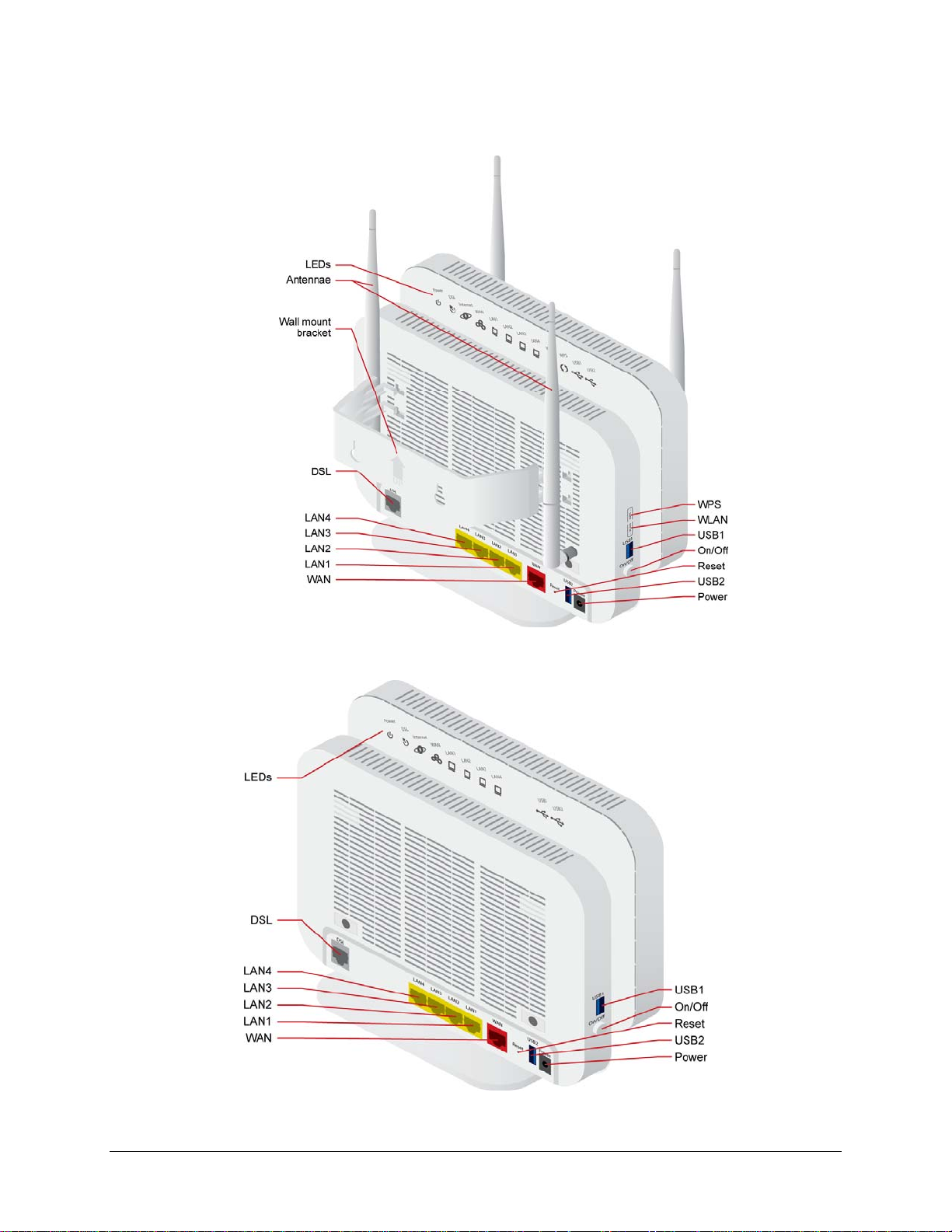
6618-W1 interfaces, LEDs and buttons
66xx/67xx Router Users Guide 19
6712-W1 interfaces, LEDs and buttons
6718-W1 interfaces, LEDs and buttons
66xx/67xx Router Users Guide 20
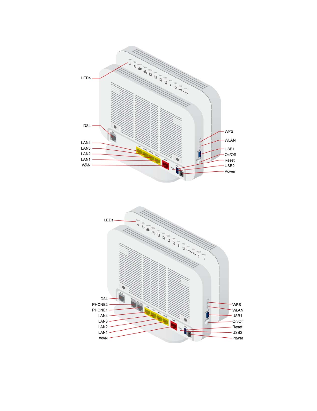
6728-W1 interfaces, LEDs and buttons
66xx/67xx Router Users Guide 21
6729-W1 interfaces, LEDs and buttons
6732-W1 interfaces, LEDs and buttons
66xx/67xx Router Users Guide 22
6738-W1 interfaces, LEDs and buttons
6748-W1 interfaces, LEDs and buttons
66xx/67xx Router Users Guide 23
6768-W1 interfaces, LEDs and buttons
66xx/67xx Router Users Guide 24
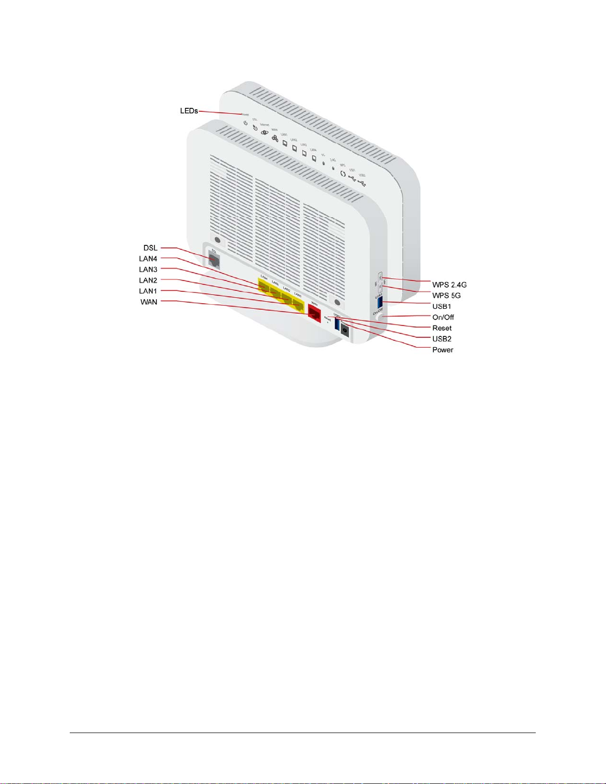
Front Panel
Note: different models have different LEDs, however the LED behavior is the same.
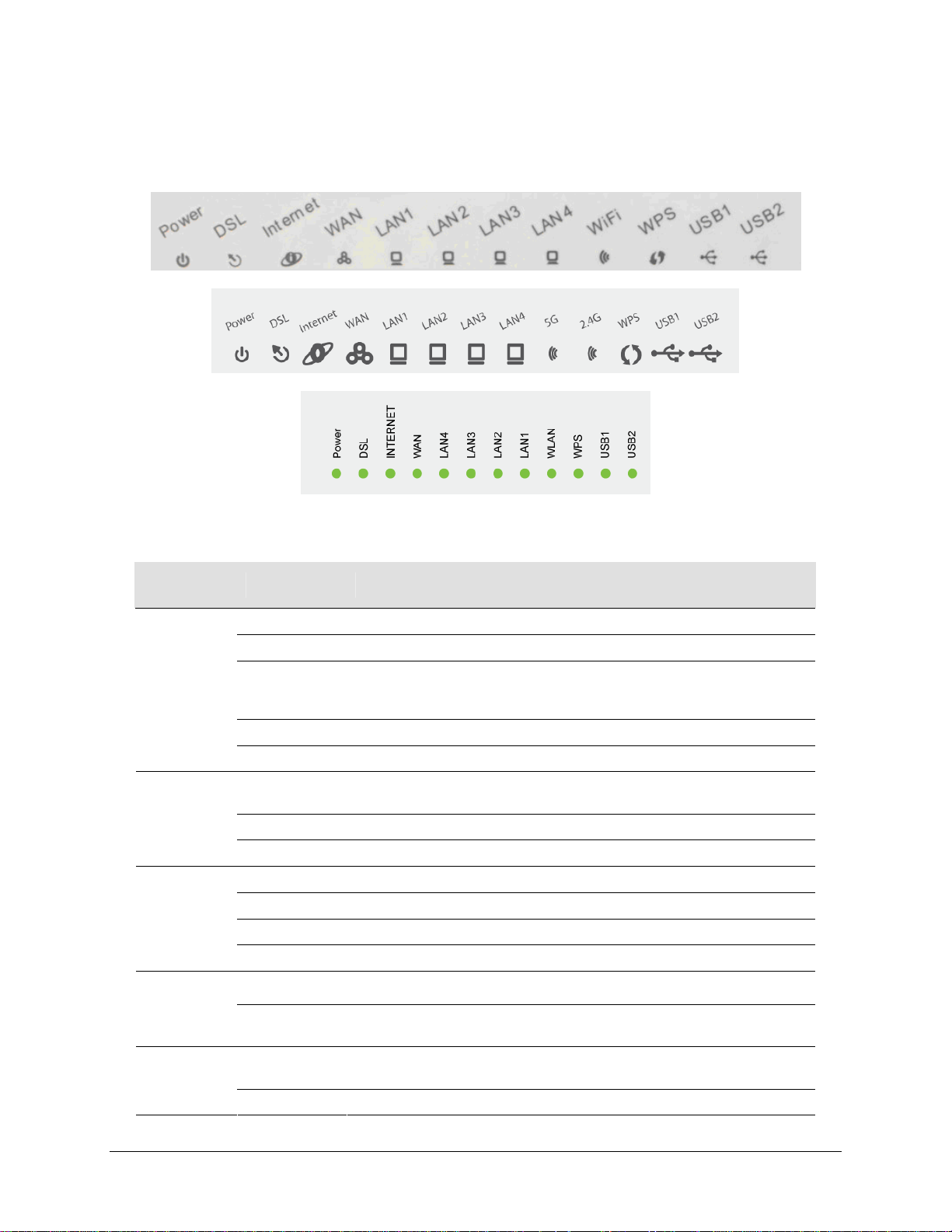
LED Descriptions
LED Mode Description
Power
DSL
(DSL1 and
DSL 2 on
bonded units)
Internet
WAN
LAN 1-4
Solid green The device is powered on and operating normally.
Blinking green The software is being up graded.
The router may not be turned on. Check if the power adapter is
Off
Solid red Router is booting up.
Blinking red The software is being upgraded.
Solid green
Blinking DSL line is training.
Off Device is powered off.
Solid green Device is connected to the internet in routing mode.
Blinking green Internet data is being transmitted.
Off Ethernet interface is disconnected.
Solid red Authentication has failed.
Solid green
Blinking green
Solid green
Blinking green The device is sending or receiving data over Ethernet.
connected to the router, the router is plugged in and the power switch
button is in the on (pushed in) state.
Connection established. The router is able to communicate with your ISP
via DSL.
The Ethernet WAN interface is connected.
The device is sending or receiving data over the Ethernet WAN interface.
Ethernet interface is successfully connected to a device through the LAN
port.
66xx/67xx Router Users Guide 25

LED Mode Description
Off Ethernet interface is disconnected.
Solid green Wireless is enabled.
WiFi
WPS
2.4G
(802.11b/g/n)
5GHz
(802.11ac)
USB 1-2
Phone 1-2
Blinking green Wireless traffic activity.
Off Wireless is disabled.
Solid green Connection has been established using the Wi-Fi Protected Setup.
Blinking green Connection is being n egotiated using the Wi-Fi Protected Setup.
Off Wi-Fi Protected Setup disabled.
Solid green 2.4GHz wireless is enabled.
Blinking green 2.4GHz wireless traffic activity.
Off 2.4GHz wireless is disabled.
Solid green 5GHz wireless is enabled.
Blinking green 5GHz wireless traffic activity.
Off 5GHz wireless is disabled.
Solid green A connection to a 3G or USB flash disk has established.
Blinking green Data is being transmitted.
Off No signal detected.
Solid green The phone port is configured
Off The phone port is not configured
66xx/67xx Router Users Guide 26
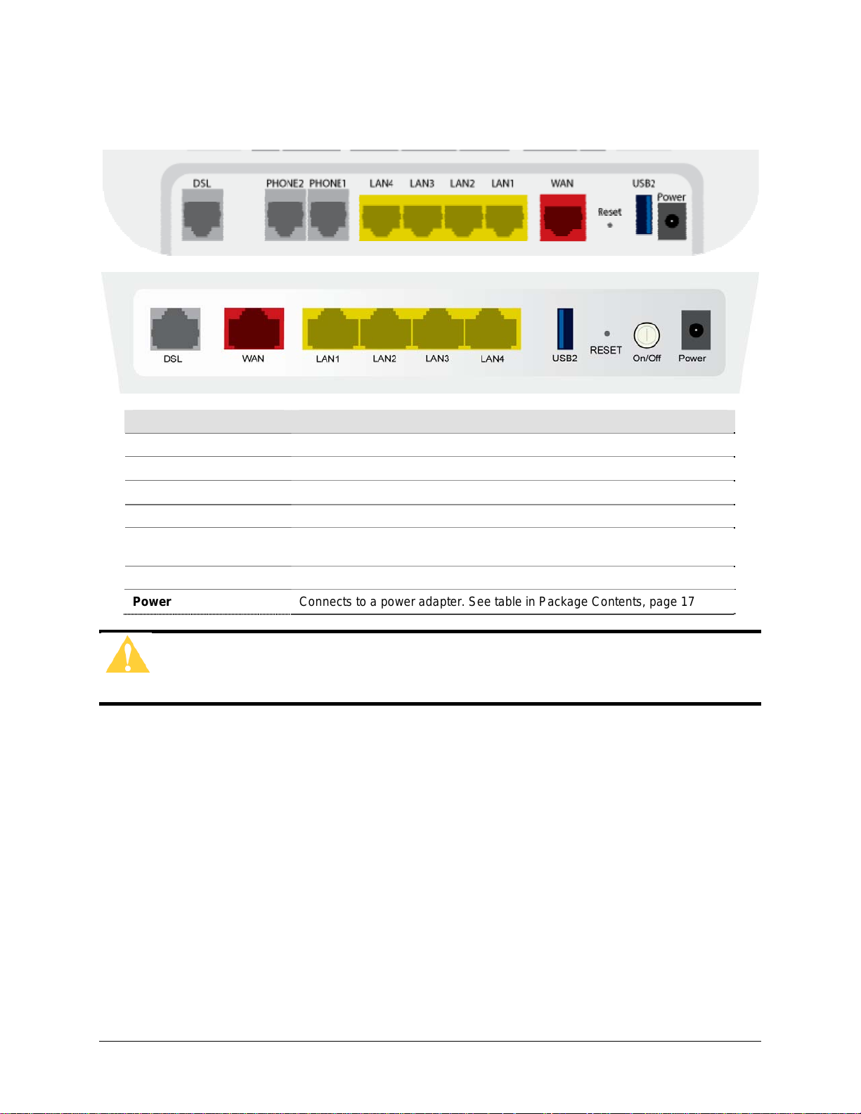
Back Panel
Port Description
DSL
LAN1 – LAN4
PHONE1 – PHONE 2
WAN
Reset / Default
USB 2
Power
Caution: Do not press the Reset button unless you want to clear the current
settings.
RJ-11 cable connects to incoming DSL line
RJ-45 connects the unit to an Ethernet device such as a PC or a switch.
RJ-11 FXO port. Connect the gateway to a PSTN line with telephone cable.
For connecting Ethernet cable to provide an Ethernet uplink.
Restores the factory default settings. Press the button for at least 1 second
and then release it. The router will reboot and return to its default settings.
USB port, for connecting the 3G network card.
Connects to a power adapter. See table in Package Contents, page 17
66xx/67xx Router Users Guide 27
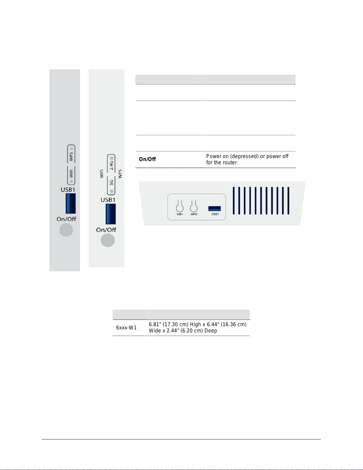
Side Panel
Port Description
WiFi
WPS
USB1
On/Off
WLAN switch, for enabling or
disabling the WLAN function.
Enables WPS Push Button Connect
(PBC) mode. If WPS is enabled,
press this button, and then the
wireless router starts the negotiation
of PBC mode.
USB port, for connecting USB
storage devices.
Power on (depressed) or power off
for the router.
Unit Dimensions
Model Unit Dimensions
6xxx-W1
6.81" (17.30 cm) High x 6.44" (16.36 cm)
Wide x 2.44" (6.20 cm) Deep
66xx/67xx Router Users Guide 28
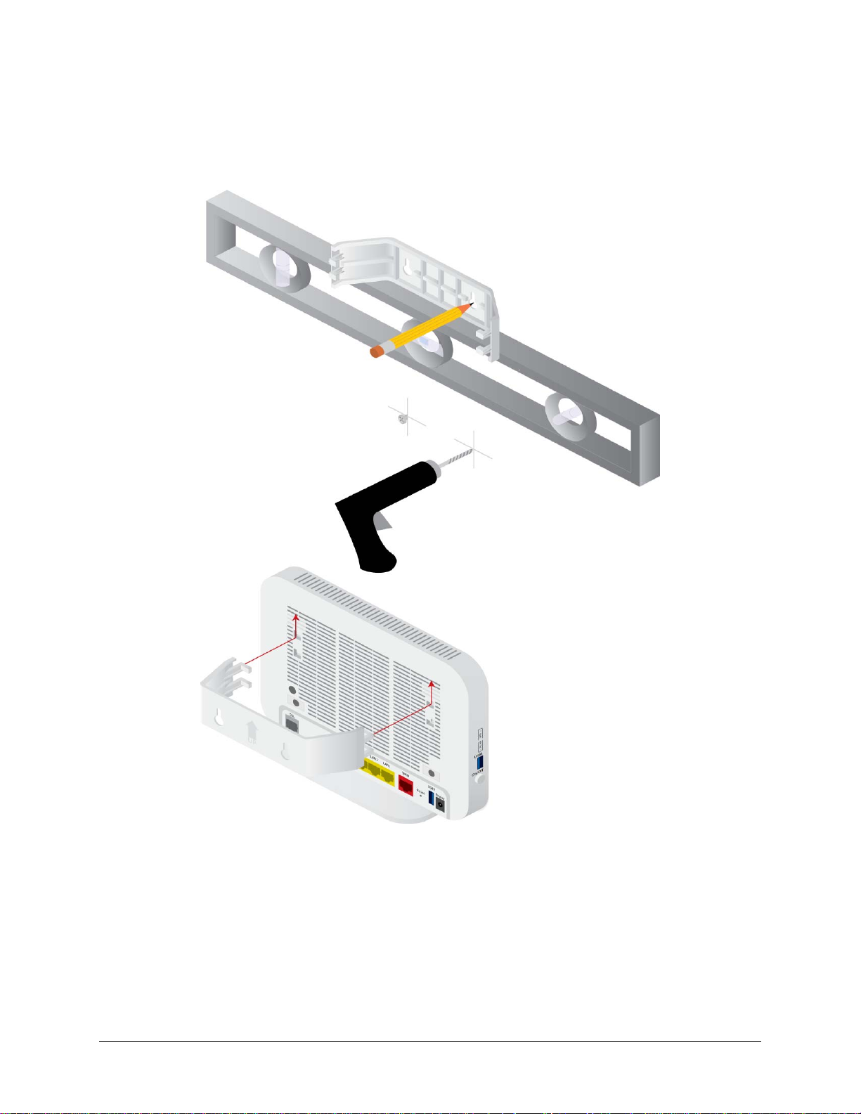
Wall Mount
Newer 6xxx units may be wall mounted with the wall mounting bracket that comes with
the unit.
66xx/67xx Router Users Guide 29

Chapter 2 Hardware Installation and PC Setup
Overview
This chapter provides basic instructions for connecting the gateway to a computer or a
LAN, a telephone, and to the Internet using the WAN interface. The first part provides
instructions to set up the hardware, and the second part describes how to prepare your
PC for use with the gateway. Refer to Chapter 3, The Web User Interface on page 35 for
configuration instructions.
It is assumed that you have already subscribed to WAN service with your telephone
company or other Internet service provider (ISP).
Connecting Your Hardware
Shut down your PC before connecting the gateway. To connect the gateway:
1. Connect the WAN interface:
The 6xxx-W1 devices support different WAN interfaces: DSL or Ethernet.
Note: Only one WAN interface can be active at a time.
2. Connect the PC to the gateway
To use the Ethernet connection, connect the Ethernet cable from the computer
directly to one of the four ports labelled LAN on the back of the gateway.
66xx/67xx Router Users Guide 30

3. Connect the power adapter
Complete the process by connecting the AC power adapter to the Power connector
on the back of the device and plug the adapter into a wall outlet or power strip. Then
turn on and boot up your PC and any LAN devices, such as hubs or switches, and
any computers connected to them.
For single line gateways (non bonded xDSL)
Complete the process by connecting the AC power adapter to the Power connector
on the back of the device and plug the adapter into a wall outlet or power strip. Then
turn on and boot up your PC and any LAN devices, such as hubs or switches, and
any computers connected to them.
For situations where a phone is also used:
66xx/67xx Router Users Guide 31

For bonded gateways (6728-W1):
The 6728-W1 can be configured for single or bonded line operation. A Y–cable is
provided. Use both the wire pairs marked “Inner” and “Outer” connected to two
network interface outlets for bonded operation. For single line opera tion, use only
the wire marked “Outer.”
For bonded situations where a phone is also used:
66xx/67xx Router Users Guide 32

Configuring Your Computer
Prior to accessing the gateway through the LAN or the USB port, note the following
necessary configurations:
Your PC’s TCP/IP address: 192.168.1.__( the last number is any number between 2 and
254)
The gateway’s default IP address: 192.168.1.1
Subnet mask: 255.255.255.0
Below are the procedures for configuring your computer. Follow the instructions for the
operating system that you are using.
If you used the Ethernet cable to connect your gateway and PC, you do not need any
specific driver installation.
Windows 2000
1. In the Windows taskbar, click the Start button and point to Settings, Control Panel,
and Network and Dial-up Connections (in that order).
2. Click Local Area Connection. When you have the Local Are a Connection Status
window open, click Properties.
3. Listed in the window are the installed network components. If the list includes
Internet Protocol (TCP/IP), then the protocol has already been enabled, and you
can skip to Step 9.
4. If Internet Protocol (TCP/IP) does not appear as an installed component, then click
Install.
5. In the Select Network Component Type window, click on protocol and then th e
Add button.
6. Select Internet Protocol (TCP/IP) from the list and then click on OK.
7. If prompted to restart your computer with the new settings, click OK.
8. After your computer restarts, click the Network and Dial-up Connections icon
again, and right click on the Local Area Connection icon and then select
Properties.
9. In the Local Area Connection Properties dialog box, select Internet Protocol
(TCP/IP) and then click Properties.
10. In the Internet Protocol (TCP/IP) Properties dialog box, click the radio button
labelled Use the following IP address and type 192.168.1.x (where x is any
number between 2 and 254) and 255.255.255.0 in the IP address field and Subnet
Mask field.
11. Click OK twice to save your changes and then close the Control Panel.
66xx/67xx Router Users Guide 33

Windows XP
Windows 7
1. In the Windows taskbar, click the Start button and point to Settings and then click
Network Connections.
2. In the Network Connections window, right click on the Local Area Connection
icon and click on Properties.
3. Listed in the Local Area Connection window are the installed network com ponents.
Make sure the box for Internet Protocol (TCP/IP) is checked and then click
Properties.
4. In the Internet Protocol (TCP/IP) Properties dialog box, click the radio button
labelled Use the following IP address and type 192.168.1.x (where x is any
number between 2 and 254) and 255.255.255.0 in the IP address field and Subnet
Mask field.
5. Click OK twice to save your changes and then close the Control Panel.
1. In the Windows taskbar, click the Start button and point to Control Panel and then
click Network and Internet.
2. In the Network and Internet window, click Network and Sharing Center.
3. In the left panel click Change adapter settings.
4. In the Network Connections screen, right click Local Area Connection and sel ect
Properties.
5. Listed in the Local Area Connection window are the installed network com ponents.
Select Internet Protocol Version 4 (TCP/IP v4) is checked and then click
Properties.
6. In the Internet Protocol Version 4 (TCP/IP v4) dialog box, click the radio button
labelled Use the following IP address and type 192.168.1.x (where x is any
number between 2 and 254) and 255.255.255.0 in the IP address field and Subnet
Mask field.
7. Click OK the Close to save your changes and then close the Control Panel.
66xx/67xx Router Users Guide 34

Chapter 3 The Web User Interface
The 6xxx gateways have a Wide Area Network (WAN) connection which connects to your
Internet Service Provider (ISP) via a DSL, Ethernet interface, or a 3G connection. The Local Area
Network (LAN) connections are where you plug in your local computers to the gateway. The 6xxx
also has a wireless interface. The gateway is normally configured to automatically provide all the
PCs on your network with Internet addresses.
Your gateway may be pre-configured with your ISP configuration to ease your installation.
Please contact your ISP if you need information on how to connect the gateway to your ISP. To
set up your gateway with a basic configuration required by your service provider, you can use the
Quick Setup form the top of the navigation bar. In order for this to work, all other WAN services
must first be removed. To remove services, from the top navigation bar select Quick Setup.
If you connected a PC (rather than a hub or a switch) directly to the gateway, your LAN consists
of that PC. You may also create connections for various protocol options by creating new
connections.
To configure your device you will first need to log in to the gateway.
Note: Before configuring your gateway, make sure you have followed the instructions in Chapter
2, Hardware Installation and PC Setup on page 30. You should have your PCs configured for
DHCP mode (if your gateway will be), and have proxies disabled on your browser. If you see a
login redirection screen when you access the web interface, verify that JavaScript support is
enabled in your browser. Also, if you do not get the screen shown below, you may need to delete
your temporary Internet files.
Log in to the Gateway
This section explains how to log in to your gateway.
1. Launch your web browser.
2. Enter the URL http://192.168.1.1
A login screen like the one below will be displayed after you connect to the user interface.
in the address bar and press Enter.
3. Enter your user name and password, and then click on OK to displ ay the user interface.
The default admin user name / password is admin / adminXXXXXX, where XXXXXX is the
last six digits of the serial number of the unit; both user name and password are case
sensitive.
66xx/67xx Router Users Guide 35

Note: There are three default user name and password combinations; admin, support, and user.
All passwords are case sensitive and can be changed at any time. For informati on about password
administration, see Passwords on page 165.
Summary
Note: For security reasons you should change your password as soon as possible.
The user / user name and password combination provides limited access to the gateway. With
this password you can view the configuration, run diagnostics, and change the LAN side
configuration such as the WiFi, but you cannot change the WAN configuration.
The support/supportXXXXXX combination allows an ISP technician to access the gateway from
the WAN only to perform maintenance and run diagnostics. The XXXXXX are the last six
digits of the serial number of the unit.
The admin / adminXXXXXX combination can perform all functions.
Access the general information of the gateway by clicking Summary under Device Info. This
screen shows details of the gateway such as the version of the software, bootloader, LAN IP
address, etc. It also displays the current status of your WAN connection as shown below.
66xx/67xx Router Users Guide 36

WAN Information
Display the WAN status report from the gateway by clicking WAN under Device Info. The graphic
below shows the screen when a WAN connection is set up.
Statistics
LAN Statistics
Display LAN statistics by clicking LAN under Statistics
66xx/67xx Router Users Guide 37

WAN Statistics
Display WAN statistics by clicking WAN Service under Statistics.
xTM Statistics
Display ATM statistics by clicking xTM under Statistics.
66xx/67xx Router Users Guide 38

xDSL Statistics
Display VDSL statistics by clicking xDSL under Statistics. Information contained in this screen is
useful for troubleshooting and diagnostics of connection problems.
To view the statistics for one of the bonding lines, select the line from the Bonding Line
Selection dropdown.
66xx/67xx Router Users Guide 39

xDSL BER Test
The xDSL Bit Error Rate (BER) test determines the quality of the VDSL connection. The test is
performed by transferring idle cells containing a known pattern and comparing the received data
with this known pattern to check for any errors The BER Test reflects the ratio of error bits to the
total number transmitted.
To run a BER test:
1. On the bottom of the xDSL statistics page, click xDSL BER Test
2. In the xDSL BER Test – Start screen select the duration of the test from the Tested Time
(sec) drop down, then click Start.
3. Check the results.
66xx/67xx Router Users Guide 40

RTCP
Real-Time Packet Protocol (RTP) statistics can be used to determine activity sent into the
network or received from the network on the VoIP lines. RTP is used with Real-time Control
Protocol (RTCP) which monitors transmission statistics through control packets sent into or
received from the network.
Cumulative statistics are kept across calls
Packets Sent: The cumulative count of data bytes in the packets sent to the network
Bytes Sent: The cumulative count of data bytes in the packets sent to the network
Bytes Received: The cumulative count of data bytes in the packets received from the network
Packets Lost: The number of packets not received based upon sequence numbers
Packets Discarded: The number of packets received but discarded
RTCP Sent: The number of control packets sent into the network
RTCP Received: The number of control packets received from the network
RTCP XR Sent: The number of extended reporting control packets sent into the network (should be
the same as RTCP Sent)
RTCP XR Received: The number of extended reporting control packets received from the network
Jitter statistics are kept from the previous call
Jitter (ms): The average delay variation (Jitter) between RTP packets
Peak Jitter (ms): The peak delay variation (Jitter) between RTP packets
Minimum Jitter Buffer (ms): The least delay an RTP packet had passing through the Jitter buffer
Maximum Jitter Buffer (ms): The greatest delay an RTP packet had passing through the Jitter
buffer
Average Jitter Buffer (ms): The average delay an RTP packet had passing through the Jitter
buffer
Round Trip Delay (ms): The two way network delay
Peak Round Trip Delay (ms): The worst two way network delay
Overruns: Number of packets received that could not be sent to the Jitter buffer since it was full
Underruns: The number of times the Jitter buffer was empty
66xx/67xx Router Users Guide 41

Voice Quality statistics are kept from the previous call
MOS Listening Quality: Mean Opinion Score. On a scale from 0 (poor) to 5 (good)
MOS Conversation Quality: Mean Opinion Score. On a scale from 0 (poor) to 5 (good)
Route Table
Access the routing status report from the gateway by clicking Route under Device Info.
ARP Table
Display the ARP status report by clicking ARP under Device Info.
ARP (Address Resolution Protocol) maps the IP address to the physical address, labelled HW
Address (the MAC address) and identifies computers on the LAN.
66xx/67xx Router Users Guide 42

DHCP Table
Display the DHCP lease information by clicking DHCP under Device Info.
DHCP (Dynamic Host Control Protocol) allows the modem to automatically assign IP addresses,
to connected devices. By default, your modem gateway set up to assign devices addresses from
192.168.1.2 to 192.168.1.254.
IGMP
Display the IGMP stream information by clicking IGMP under Device Info.
IGMP (Internet Group Management Protocol) is used to create group memberships for multicast
streams. Normally IGMP is used for streaming video and other applications such as gaming, to
provide more efficient use of the network resources for these types of applications.
66xx/67xx Router Users Guide 43

System Performance
Graphically displays the CPU and memory performance of the device.
66xx/67xx Router Users Guide 44

Chapter 4 Quick Setup
The Automatic Configuration feature will automatically detect the first usable PVC and
automatically detect PPPoE, PPPoA, and Bridge Protocol (with DHCP Server available). To use
the Automatic Configuration feature, check the Automatic Configuration option.
Note: In order for the automatic configuration to work, all previously defined WAN configurations must
be removed.
Quick Setup with Automatic Configuration
To enable the Automatic Configuration feature:
1. From the navigation pane on the left select Quick Setup.
66xx/67xx Router Users Guide 45

2. Select Automatic Configuration.
3. Enter the SSID.
4. You will need to enter the PPP username and password as provided by your ISP.
5. Click Apply/Save.
You will see a progress screen:
When the connection is complete you will see the Service Setup summary screen.
66xx/67xx Router Users Guide 46

Quick Setup with Automatic Configuration Disabled
1. From the navigation pane on the left select Quick Setup.
2. Specify VPI and VCI as directed by your ISP.
3. Select the Encapsulation Mode as directed by your ISP.
4. Under WAN Service Configuration select the protocol for the WAN connection from the
Protocol dropdown as directed by your ISP.
Depending on the protocol selected further parameters are presen ted.
66xx/67xx Router Users Guide 47

PPPoE and PPPoA: You will need to enter the PPP username and password as provided
by your ISP.
For PPPoE or DHCP, if desired, the DSL Gateway can be configured with a static IP
address and Subnet Mask for the LAN interface to correspond to your LAN’s IP Subnet. To
use a static IP address check the Use Static IP Address option, then enter the IP Address,
Subnet Mask, Default Gateway and DNS server.
66xx/67xx Router Users Guide 48

IPoA: For IPoA your ISP will supply information for IP Address, Subnet Mask, and DNS
server.
DHCP: With DHCP option you do not set any other options.
Bridge: With the Bridge option you do not set any other options.
66xx/67xx Router Users Guide 49

5. With Quick Setup the gateway’s wireless option is automatically set up and you will need to
enter the SSID.
The passkey is printed on the bottom of the unit. On the bottom of the unit there is a label which says,
“WPA Passphrase YYYYYYYYYYYY” where YYYYYYYYYYYY is the passkey for the Wireless SSID.
6. Click Apply/Save to save your settings.
66xx/67xx Router Users Guide 50

Chapter 5 Advanced Setup
This section contains advanced setup settings. To create a connection you need to define the
Layer 2 interface and the WAN service.
Configuration Types
VDSL is a PTM or ATM (ADSL fallback) based technology. The gateway supports Bridging and
Ethernet over ATM (EoA) configurations and ATM based configurations:
Bridging
Bridging (Layer 2 MAC addressing); uses Ethernet frames.
PPPoE
Point to Point Protocol over Ethernet; encapsulates PPP packet in Ethernet. (RFC 2516)
IPoE
IP over Ethernet (Layer 3 Internet Protocol addressing in Ethernet frames)
PPPoA
Point to Point Protocol over ATM, encapsulates PPP frames in ATM adaption layer 5 (AAL5)
packets.
IPoA
IP over ATM (Layer 3 Internet Protocol addressing in AAL5 packets
The table below describes the supported WAN interfaces and services supported on each interface.
WAN Interface Supported WAN Service
ATM Bridging
IPoA
IPoE/DHCP
PPPoA
PPPoE
PTM Bridging
IPoE/DHCP
PPPoE
Ethernet Bridging
IPoE/DHCP
PPPoE
To configure a connection, you first configure the connection type. EoA, PPPoA, or IPoA.
1. Add a Layer 2 interface and select the connection type.
EoA is used for PPPoE, IPoE and Bridge connections. PPPoA and IPoA are AAL5 based connections.
2. Set the WAN interface.
The WAN interface options to select are determined by the Layer 2 interface type.
66xx/67xx Router Users Guide 51

Add an ATM Layer 2 Interface
1. In the left hand menu pane, click Advanced Setup.
2. Under Advanced Setup, click Layer2 Interface then ATM Interface, then click the Add
button.
3. In the VPI and VCI text boxes enter appropriate VPI/VCI numbers.
VPI/VCI (Virtual Path Identifier/Virtual Circuit Identifier) values essentially define the “pipe”
which sends data from the upstream device to the gateway. The VPI/VCI values will be
given to you by your ISP.
4. In the DSL Latency field, select Fast and/or Interleaved.
Use the default settings. Only change to increase precedence if the interface is dedicated
for video or voice applications.
66xx/67xx Router Users Guide 52

5. Under Select DSL Link Type select the appropriate DSL link type: Select EoA for PPPoE,
IPoE, and Bridge connections.
6. From the Encapsulation Mode drop down select the appropriate option:
For EoA options (PPPoE, IPoE, Bridge) select LLC/SNAP BRIDGING
For PPPoA select VC/MUX
For IPoA select LLC/SNAP ROUTING
7. From the Service Category drop down select the type of service.
The service category selection will be provided by your ISP. The service category defines
five classes of traffic:
UBR Without PCR (Unspecified Bit Rate without Peak Cell Rate)—UBR service is suitable
for applications that can tolerate variable delays and some cell losses. Applications suitable
for UBR service include text/data/image transfer, messaging, distribution, and retrieval and
also for remote terminal applications such as telecommuting.
UBR With PCR (Unspecified Bit Rate with Peak Cell Rate).
• Specify a Peak cell Rate. The Peak cell rate is 1-3442 (cells / sec).
CBR (Constant Bit Rate): used by applications that require a fixed data rate that is
continuously available during the connection time. It is commonly used for
uncompressed audio and video information such as videoconferencing, interactive audio
(telephony), audio / video distribution (e.g. television, distance learning, and pay-perview), and audio / video retrieval (e.g. video-on-demand and audio library).
• Specify a Peak cell Rate. The Peak Cell Rate is rate is 1-3442 (cells / sec).
Non Realtime VBR (Non-Real-time Variable Bit Rate): can be used for data transfers
that have critical response-time requirements such as airline reservations, banking
transactions, and process monitoring.
• Specify a Peak cell Rate. The Peak Cell Rate is rate is 1-3442 (cells / sec).
• Sustainable Cell Rate. The maximum Sustainable Cell Rate is rate is 1-3442
(cells / sec).1-3442 (cells / sec).
• Maximum Burst Size. The maximum number of contiguous cells that can be sent
at the Peak Cell Rate. The maximum burst size is 1-1000000 (cells / sec).
Realtime VBR (Real-time Variable Bit Rate)—used by time-sensitive applications such
as real-time video. Rt-VBR service allows the network more flexibility than CBR.
• Specify a Peak cell Rate. The Peak Cell Rate is rate is 1-3442 (cells / sec).
• Sustainable Cell Rate. The maximum Sustainable Cell Rate is rate is 1-3442
(cells / sec).1-3442 (cells / sec).
• Maximum Burst Size. The maximum number of contiguous cells that can be sent
at the Peak Cell Rate. The maximum burst size is 1-1000000 (cells / sec).
If using UBR without PCR, select the IP Quality of Service (QoS) algorithm. The options
are Weighted Round Robin or Weighted Fair Queuing.
8. Select the queuing option, either Weighted Round Robin or Weighted Fair Queuing.
Use the default values unless directed by your ISP to change the values.
9. Click Apply/Save to add the appropriate WAN servi c e.
66xx/67xx Router Users Guide 53

Add a PTM Layer 2 Interface
1. In the left hand menu pane, click Advanced Setup.
2. Under Advanced Setup, click Layer2 Interface then PTM Interface, then click the Add
button.
3. Select Weighted Round Robin or Weighted Fair Queuing.
4. Enter a Default Queue Weight and a Default Queue Precedence .
5. Enter a Default Queue Shaping Rate and a Default Queue Shaping Burst Rate.
6. Click Apply/Save to add the appropriate WAN servi c e.
66xx/67xx Router Users Guide 54

Add an Ethernet Layer 2 WAN Interface
You can specify any of the gateway’s Ethernet ports as a WAN interface or LAN interface. In
other words, the GE WAN (ETHWAN) interface may be used as a LAN interface, and any of
LAN1, LAN2, LAN3 and LAN 4 may be used as a WAN interface. Only one of the Ethernet
interfaces may be selected as a WAN interface. All of the other Ethernet interfaces may be use
as LAN interfaces.
1. In the left hand menu pane, click Advanced Setup.
2. Under Advanced Setup, click Layer2 Interface then ETH Interface, then click the Add
button.
3. Select the Ethernet port for the WAN interface.
Normally you would select ETHWAN, the GigE Ethernet port, though one of the LAN ports
could be selected as well.
4. Click Apply/Save to add the appropriate WAN servi c e.
WAN Service
Use the WAN Service page to create a PPPoE, IPoE or Bridging Interface.
66xx/67xx Router Users Guide 55

Add a PPPoE WAN Service
1. Add an EoA Layer 2 interface or an Ethernet WAN interface as described above (see Add an
ATM Layer 2 Interface on page 52).
2. Under Advanced Setup click WAN Service then click Add.
3. On the WAN Service Interface Configuration page, select the interface associated with the
PPPOE interface from the drop down, then click Next.
4. On the WAN Service Configuration page, select PPP over Ethernet (PPPoE).
5. Optionally enter a name if you wish to customize the descriptio n shown for the service.
6. Optionally specify the 801.1P priority and 802.1Q VLAN tagging parameters, and then click
Next. For untagged service, set the parameter to -1 to both 802.1P and 802.1Q VLAN ID.
By default the 802.1P and 802.1Q values are set to -1, which means that the parameters
are ignored.
7. Specify the address type, IPv4 only or dual stack (IPv4 and IPv6).
The IPv6 option enables IPv6 on the WAN interface. Use only when IPv6 is required.
66xx/67xx Router Users Guide 56

8. Click Next.
9. On the PPP Username and Password page you will need the following information:
PPP Username: Your account from ISP to access Internet.
PPP Password: The password assigned by your ISP.
Note: If you set the username/password to default/default, the modem will redirect the
user to a web page within the modem to change their password when they first log on.
PPPoE Service Name: Server name of network ISP. No need to set this.
Authentication Method: Authentication mode of network ISP. Default is AUTO.
MTU: the Maximum transmission unit (MTU) value may be set for your needs. Higher
MTU can provide for a more efficient link because each packet will carry more data while
the overhead in the packet such as header information does not get larger with the size
of the packet. So the bulk throughput on the link will go up. Generally a large packet size
can occupy the time on the link, so the higher MTU can increase lag time and minimum
latency which is not appropriate for all applications.
MTU size can be 576-1492.
Enable KeepAlive:
• KeepAlive Time: The interval in which the PPPoE client will send out keep alive
message to the PPPoE server to keep the PPPoE session up.
• KeepAlive Max Fail: The maximum number of retries the gateway will attempt if the
PPP client encounters an error. For example if the number is 1 the gateway will only
retry once.
Enable NAT: Enables Network Address Translation. See NAT on page 81.
Enable FireWall: Enables Firewall. See Firewall on page 85.
PPP Dial Up Delay Seconds: The number of seconds the gateway will pause before
66xx/67xx Router Users Guide 57

attempting PPP authentication. The default (0) means that the gateway will pause a
random number of seconds before attempting authentication. This helps prevents the
PPP server from being flooded with authentication requests after a power shutdown or a
reset.
Limit Retry Time of PPP Password on Authentication Error: Number of times the
gateway should re-attempt PPPoE authentication after a failure. When the Retry Timer is
disabled, the device will keep retrying using the PPP username and password.
NAT Public Address (available if NAT is enabled). Enter 0.0.0.0 to specify that the
device should use pubic IP addresses provided by the network.
Enable Fullcone NAT: RFC 3489 defines four types of Network Address Translation
(NAT). Fullcone NAT. As with other types of NAT there is a mapping from a public IP
address to a private IP address. The external public IP address is extended with the
external port. With Fullcone NAT once the mapping is created any external host may
send packets to the private IP address by sending to the external IP address and port.
Other types of NAT have restrictions such as the sending IP address must initially have
had packets sent from the private IP address and port regardless of the external port, or
from the private IP address and the external port.
Dial on demand: When this mode is selected, the connection that has no traffic within
assigned disconnect timeout (e.g. 1 minute) will be automatically disconnected. The
connection will be activated again when traffic arrives. This function is advantageous for
users who are charged with online time. It should be noted that some programs
automatically link to Internet. Connections will not be disconnected under these data
streams.
• Inactivity Timeout: When Dial on demand is selected, this input box indicates that
after how long the connection will be disconnected in the absence of traffic. If the
value is 0, connection will not be disconnected.
Manual Connect: connect/disconnect PPPoE connection manually
PPP IP extension: Allows only one PC on the LAN. The public IP address assigned by
the remote using the PPP/IPCP protocol is actually not used on the WAN PPP interface.
Instead, it is forwarded to the PC’s LAN interface through DHCP.
Only one PC on the LAN can be connected to the remote since the DHCP server within
the VDSL gateway has only a single IP address to assign to a LAN device. NAT and
firewall are disabled when this option is selected. The VDSL gateway becomes the
default gateway and DNS server to the PC through DHCP using the LAN interface IP
address. The VDSL gateway extends the IP subnet at the remote service provider to the
LAN PC. That is, the PC becomes a host belonging to the same IP subnet. The VDSL
gateway bridges the IP packets between WAN and LAN ports, unless the packet is
addressed to the gateway’s LAN IP address.
MAC Clone: Clicking the Clone the PC MAC Address button will use the MAC address
from the connected PC for the MAC address of the gateway.
Use Static Ipv4 Address: Enter the Static IP V4 address
Enable PPP Debug Mode: Used to debug PPPoE issues. Use only when instructed by
your ISP.
Bridge PPPoE Frames Between WAN and Local Ports: By default the bridge PPPoE
frame between WAN and local ports is on. This allows a PC behind the modem to be the
PPPoE termination point. PPPoE authentication is passed on to the PC instead of to the
gateway. If there are multiple PCs then, each one will have a PPPoE authentication. Note
that this option is not applicable for PPPoA.
Enable IGMP Multicast Proxy: Configures the gateway for IGMP snooping so the
gateway can keep limit multicast traffic.
Enable MLD Multicast Proxy: Configures the gateway to act as a proxy by issuing MLD
host messages for the hosts that have been discovered through MLD interfaces.
Enable MLD Multicast Proxy is for IGMP in IPv6 mode.
10. Click Next.
66xx/67xx Router Users Guide 58

11. On the Routing — Default Gateway page set the priority of WAN interfaces u se d as defa ult
gateways then click Next
If multiple WAN interfaces are configured, you can define the priority by their position in the
Selected Default Gateway Interfaces window. The default gateway will use the first
Interface that comes up.
Change the priority order by removing all items from the Selected Default Gateway
Interfaces window by selecting them, then clicking the right arrow button. Select the items in
the priority order, then click the left arrow to move them into the Selected Default Gateway
Interfaces window.
12. On the DNS Server Configuration page set the priority of WAN interfaces to be used as
DNS server interfaces, or specify a static DNS Primary and Secondary server, and then click
Next.
If multiple WAN interfaces are configured, you can define the priority by their position in the
Selected DNS Server Interfaces window. Top is the highest priority; bottom the lowest.
66xx/67xx Router Users Guide 59

Change the priority order by removing all items from the Selected DNS Server Interfaces
window by selecting them, then clicking the right arrow button. Select the items in the priority
order, then click the left arrow to move them into the Selected DNS Server Interfaces
window.
For a Static DNS IP Address, enter a primary and secondary DNS server for your modem.
13. On the WAN Setup – Summary page, review your settings and click Apply/Save to accept
the settings. To change your settings, click the Back button on the WAN Setup – Summary
page (do not click the browser Back button).
In the Wide Area Network (WAN) Service Setup page, you will see the new WAN interface
added.
Add an IPoE WAN Service
1. Add an EoA Layer 2 interface or an Ethernet WAN interface as described above (see Add an
ATM Layer 2 Interface on page 52).
2. Under Advanced Setup click WAN Service then click Add.
3. On the WAN Service Interface Configuration page, select the interface associated with the
IPoE interface from the drop down, then click Next.
66xx/67xx Router Users Guide 60

4. On the WAN Service Configuration page, select IP over Ethernet.
5. Optionally specify the 801.1P priority and 802.1Q VLAN tagging parameters, and then click
Next. For untagged service, set the parameter to -1 to both 802.1P and 802.1Q VLAN ID.
By default the 802.1P and 802.1Q values are set to -1, which means that the parameters
are ignored.
6. Specify the address type, IPv4 only or dual stack (IPv4 and IPv6).
The IPv6 option enables IPv6 on the WAN interface. Use only when IPv6 is required.
7. Click Next.
8. On the WAN IP Settings page you will need to enter information provided by your ISP, then
click Next.
66xx/67xx Router Users Guide 61

9. On the Network Address Translation Settings you will need to enter information provided
by your ISP, then click Next.
Enable NAT must be checked for Fullcone NAT to be used.
• NAT Public Address (available if NAT is enabled). Enter 0.0.0.0 to specify that the
device should use pubic IP addresses provided by the network.
• Enable Fullcone NAT: RFC 3489 defines four types of Network Address Transl ation
(NAT).
Fullcone NAT. As with other types of NAT there is a mapping from a public IP
address to a private IP address. The external public IP address is extended with the
external port. With Fullcone NAT once the mapping is created any external host may
send packets to the private IP address by sending to the external IP address and
port. Other types of NAT have restrictions such as the sending IP address must
initially have had packets sent from the private IP address and port regardless of the
external port, or from the private IP address and the external port.
Enable Firewall: Enables Firewall.
Enable IGMP Multicast: Configures the gateway for IGMP snooping so the gateway can
keep limit multicast traffic.
10. Click Next.
11. On the Routing — Default Gateway page set the priority of WAN interfaces u se d as defa ult
gateways then click Next.
66xx/67xx Router Users Guide 62

If multiple WAN interfaces are configured, you can define the priority by their position in the
Selected Default Gateway Interfaces window. Top is the highest priority; botto m the
lowest.
Change the priority order by removing all items from the Selected Default Gateway
Interfaces window by selecting them, then clicking the right arrow button. Select the items in
the priority order, then click the left arrow to move them into the Selected Default Gateway
Interfaces window.
12. On the DNS Server Configuration page set the priority of WAN interfaces to be used as
DNS server interfaces, or specify a static DNS Primary and Secondary server, then click
Next.
If multiple WAN interfaces are configured, you can define the priority by their position in the
Selected DNS Server Interfaces window. Top is the highest priority; bottom the lowest.
Change the priority order by removing all items from the Selected DNS Server Interfaces
window by selecting them, then clicking the right arrow button. Select the items in the priority
order, then click the left arrow to move them into the Selected DNS Server Interfaces
window.
For a Static DNS IP Address, enter a primary and secondary DNS server for your modem,
66xx/67xx Router Users Guide 63

13. On the WAN Setup – Summary page review your settings and click Apply/Save to accept
the settings. To change your settings, click the Back button on the WAN Setup – Summary
page (do not click the browser Back button).
In the Wide Area Network (WAN) Service Setup page, you will see the new WAN interface
added.
Add a Bridge WAN Service
1. Add an EoA Layer 2 interface as described above (see Add an ATM Layer 2 Interface on
page 52.)
2. Under Advanced Setup click WAN Service then click Add.
3. On the WAN Service Interface Configuration page, select the interface associated with the
bridge interface from the drop down, and then click Next.
66xx/67xx Router Users Guide 64

4. On the WAN Service Configuration page, select Bridging
14. Optionally specify the 801.1P priority and 802.1Q VLAN tagging parameters, and then click
Next. For untagged service, set the parameter to -1 to both 802.1P and 802.1Q VLAN ID.
By default the 802.1P and 802.1Q values are set to -1, which means that the parameters
are ignored.
5. Click Next.
6. In the WAN Setup – Summary page, review the settings for this interface. Click Apply/Save
to accept the settings.
If you made a mistake on the configuration and want to make changes to it, select the
Remove check box and click the Remove button.
In the Wide Area Network (WAN) Service Setup page, you will see the new WAN interface
added.
66xx/67xx Router Users Guide 65

Add a PPPoA WAN Service
1. Add a PPPoA Layer 2 interface as described above (see Add an ATM Layer 2 Interface on
page 52).
2. Under Advanced Setup click WAN Service then click Add.
3. On the WAN Service Interface Configuration page, select the link associated with the
PPPoA interface from the drop down, and then click Next.
4. On the WAN Service Configuration page, enter a name if you wish to customize the
description shown for the service.
66xx/67xx Router Users Guide 66

5. Specify the address type, IPv4 only or dual stack (IPv4 and IPv6).
6. Click Next.
7. On the PPP Username and Password page you will need to enter information provided b y
your ISP. When you are done, click Next.
PPP Username: Your account from ISP to access Internet.
PPP Password: The password assigned by your ISP.
Authentication Method: Authentication mode of network ISP. Default is AUTO.
MTU: the Maximum transmission unit (MTU) value may be set for your needs. Higher
MTU can provide for a more efficient link because each packet will carry more data while
the overhead in the packet such as header information does not get larger with the size
of the packet. So the bulk throughput on the link will go up. Generally a large packet size
can occupy the time on the link, so the higher MTU can increase lag time and minimum
latency which is not appropriate for all applications.
Enable KeepAlive: Enables/disables TCP keep alive packets.
• KeepAlive Timer: When Enable KeepAlive is selected, this input box indicate s
how often the device should send keep alive packets.
• KeepAlive Max Fail: Number of times the gateway should re-attempt the
connection after a failure.
PPP Dial Up Delay Seconds: The number of seconds the gateway will pause before
attempting PPP authentication. The default (0) means that the gateway will pause a
random number of seconds before attempting authentication. This helps prevents the
PPP server from being flooded with authentication requests after a power shutdown or a
reset.
Limit Retry Time of PPP Password on Authentication Error: Number of times the
gateway should re-attempt PPPoE authentication after a failure.
NAT Public Address (available if NAT is enabled). Enter 0.0.0.0 to specify that the
device should use pubic IP addresses provided by the network.
Enable Fullcone NAT: RFC 3489 defines four types of Network Address Translation
(NAT). Fullcone NAT. As with other types of NAT there is a mapping from a public IP
address to a private IP address. The external public IP address is extended with the
external port. With Fullcone NAT once the mapping is created any external host may
send packets to the private IP address by sending to the external IP address and port.
Other types of NAT have restrictions such as the sending IP address must initially have
had packets sent from the private IP address and port regardless of the external port, or
from the private IP address and the external port.
Dial on demand
: When this mode is selected, the connection that has no traffic within
assigned disconnect timeout (e.g. 1 minute) will be automatically disconnected. The
connection will be activated again when traffic arrives. This function is advantageous for
users who are charged with online time. It should be noted that some programs
automatically link to Internet. Connections will not be disconnected under these data
streams.
• Inactivity Timeout: When Dial on demand is selected, this setting indicates that
after how long the connection will be disconnected in the absence of traffic. If the
value is 0, connection will not be disconnected.
Manual Connect: connect/disconnect PPPoE connection manually.
MAC Clone: Clicking the Clone the PC MAC Address button will use the MAC address
from the connected PC for the MAC address of the gateway.
Use Static IPv4 Address: Defines a static IP address (v4) which you enter in the IPv4
Address text box which is displayed when the Use Static IPv4 Address check box is
selected.
Enable PPP Debug Mode: Used to debug PPPoE issues. Use only when instructed by
your ISP.
66xx/67xx Router Users Guide 67

Enable IGMP Multicast Proxy: Configures the gateway for IGMP snooping so the
gateway can keep limit multicast traffic.
8. On the Routing — Default Gateway page set the priority of WAN interfaces use d as default
gateways then click Next
If multiple WAN interfaces are configured, you can define the priority by their position in the
Selected Default Gateway Interfaces window. Top is the highest priority; bottom the
lowest.
Change the priority order by removing all items from the Selected Default Gateway
Interfaces window by selecting them, then clicking the right arrow button. Select the items in
the priority order, then click the left arrow to move them into the Selected Default Gateway
Interfaces window.
9. On the DNS Server Configuration page set the priority of WAN interfaces to be used as
DNS server interfaces then click Next
If multiple WAN interfaces are configured, you can define the priority by their position in the
Selected DNS Server Interfaces window. Top is the highest priority; bottom the lowest.
Change the priority order by removing all items from the Selected DNS Server Interfaces
window by selecting them, then clicking the right arrow button. Select the items in the priority
order, then click the left arrow to move them into the Selected DNS Server Interfaces
window.
For a Static DNS IP Address, enter a primary and secondary DNS server for your modem,
10. On the WAN Setup – Summary page review your settings and click Apply/Save to accept
the settings. To change your settings, click the Back button on the WAN Setup – Summary
page (do not click the browser Back button).
In the Wide Area Network (WAN) Service Setup page, you will see the new WAN interface
added.
66xx/67xx Router Users Guide 68

Add an IPoA WAN Service
1. Add an IPoA Layer 2 interface as described above (see Add an ATM Layer 2 Interface on
page 52).
1. Under Advanced Setup click WAN Service then click Add.
2. WAN Service Interface Configuration page, select the interface associated with the IPoA
interface from the drop down, then click Next
3. On the WAN Service Configuration page, enter a name if you wish to customize the
description shown for the service, then click Next.
66xx/67xx Router Users Guide 69

4. On the WAN IP Settings page enter a WAN IP address, WAN subnet mask, and DNS
server settings as instructed by your ISP, then click Next.
5. On the Network Address Translation Settings you will need to enter information provided
by your ISP, then click Next.
Enable NAT must be checked for Fullcone NAT to be used.
• NAT Public Address (available if NAT is enabled). Enter 0.0.0.0 to specify that the
device should use pubic IP addresses provided by the network.
• Enable Fullcone NAT: RFC 3489 defines four types of Network Address Transl ation
(NAT). Fullcone NAT. As with other types of NAT there is a mapping from a public IP
address to a private IP address. The external public IP address is extended with the
external port. With Fullcone NAT once the mapping is created any external host may
send packets to the private IP address by sending to the external IP address and
port. Other types of NAT have restrictions such as the sending IP address must
initially have had packets sent from the private IP address and port regardless of the
external port, or from the private IP address and the external port.
Enable Firewall: Enables Firewall.
Enable IGMP Multicast: Configures the gateway for IGMP snooping so the gateway can
keep limit multicast traffic.
6. On the Routing — Default Gateway page set the priority of WAN interfaces use d as default
gateways then click Next
66xx/67xx Router Users Guide 70

If multiple WAN interfaces are configured, you can define the priority by their position in the
Selected Default Gateway Interfaces window. Top is the highest priority; bottom the
lowest.
Change the priority order by removing all items from the Selected Default Gateway
Interfaces window by selecting them, then clicking the right arrow button. Select the items in
the priority order, then click the left arrow to move them into the Selected Default Gateway
Interfaces window.
7. On the DNS Server Configuration page set the priority of WAN interfaces to be used as
DNS server interfaces then click Next
If multiple WAN interfaces are configured, you can define the priority by their position in the
Selected DNS Server Interfaces window. Top is the highest priority; bottom the lowest.
Change the priority order by removing all items from the Selected DNS Server Interfaces
window by selecting them, then clicking the right arrow button. Select the items in the priority
order, then click the left arrow to move them into the Selected DNS Server Interfaces
window.
8. For a Static DNS IP Address, enter a primary and secondary DNS server for your modem,
9. On the WAN Setup – Summary page review your settings and click Apply/Save to accept
the settings. To change your settings, click the Back button on the WAN Setup – Summary
page (do not click the browser Back button).
In the Wide Area Network (WAN) Service Setup page, you will see the new WAN interface
added.
10. WAN Setup — Summary
When the settings are complete, the next screen shows a WAN Setup – Summary screen
displaying the WAN configurations made.
Make sure that the settings on the WAN Setup - Summary screen match the settings provided
by your ISP. If all settings are correct, click the Apply/Save button to save these settings; if not,
click Back to make any modifications (do not click the browser Back button).. If you want to
change any item after saving, click Edit to make any modifications.
66xx/67xx Router Users Guide 71

After the settings are saved, the below screen will follow displaying the WAN settings that you
made with the option to Add or Remove any of the connections that you have made.
Remove a Connection
If you want to delete a connection from the listed WAN setup, click the Remove check box next to
the connection, then click Remove.
Edit a Connection
If you want to modify a connection from the listed WAN setup, click the Edit button next to the
connection.
NOTE: Some connection settings cannot be edited after they have been created. You will need to
delete and re-add the connection to change some settings.
3G WAN Service
3G WAN service allows you to set up a WAN service for 3G mobile networks as a back up if the
DSL WAN service becomes unavailable.
Some parameters depend on the requirements of the 3G provider.
User Name/Password: Username/password for the dial up 3G WAN service. (Not all providers
require User Name/Password.)
66xx/67xx Router Users Guide 72

Authentication Method Authentication methods for connecting to the 3G mobile network. Auto is
recommended. Please follow the guidance of your ISP.
APN: The name of the access point
Dial Number: The dial up number
Idle time (in sec.): If no activity on the 3G WAN service for the designated duration the 3G
connection will be dropped.
Dial on demand: Leave blank (for manual dialing).
Dial Delay (in sec.): How long from the time DSL stops working before switching to 3G WAN
service mode. Shortening the Dial Delay could lead to excessive use of 3G service.
Default WAN Connection Select: Select the DSL OR ETHERNET option.
WAN backup mechanism: If you are using ADSL or VDSL for the WAN connection, select DSL.
USB Modem Service
USB Modem Service page displays the USB Modem service. Click add to create a USB Modem
service.
USB mobile modem setup
66xx/67xx Router Users Guide 73

VPN
The VPN (Virtual Private Network) option creates a layer 2 tunnel, so even though separated by
distance and other intervening layer 2 devices, the downstream devices appe ars to be on the
same IP subnet.
The Layer 2 connection uses Point to Point Protocol (PPP). A PPPoE WAN interface must be
created first so it can be selected as the WAN Interface.
Description: A descriptive name for the VPN tunnel
WAN Interface: The WAN Interface for the VPN tunnel.
L2TP Server IP: The IP address for the Layer 2 server.
L2TP Username/Password: The username and password to connect to the Layer 2 server.
Authentication: The authentication method to use when connecting to the Layer 2 server.
Enable MPPE: Enables Microsoft Point-to-Point Encryption.
MTU: The Maximum Transmission Unit size for communications between the device and the
Layer 2 server.
Enable NAT: Enable Network Address Translation.
Enable Fullcone NAT: Enable NAT with extended port numbering for the public IP address.
Enable L2TP Reconnect: Enable reconnection to the Layer 2 Server. When selected, also enter
the snooze time-out PPP in seconds (the amount of time between activities to reconnect)
and the number of retries.
Dial on demand (with idle timeout timer): Enables the ability to dynamically connect to L2TP
server when data is detected on the LAN interface for the L2TP tunnel.
Enable Firewall (SPI): Enables the Firewall with stateful packet inspection.
Once configured, click Next, then in the next screens (as with othe r WAN interfaces), move the
new Available Routed WAN Interfaces and Available WAN Interface to the selected region for
the Default Gateway and the DNS Server Configuration screens, then click Next and
Apply/Save in the Summary screen.
66xx/67xx Router Users Guide 74

Ethernet Mode
Ethernet mode allows you to select the speed of your LAN Ethernet connections. (Configure the
WAN Ethernet interface in the Advanced Setup, Layer 2, ETH Interface screen.) Modes
include—auto, 100 full, 100 half, 10 full and 10 half. If you select auto then the gateway will use
the common mode that all the connected interfaces can operate at.
If the GE WAN port is the Ethernet WAN interface, it may be deleted as an Ethernet WAN
interface, so the port may be used as a LAN port.
66xx/67xx Router Users Guide 75

LAN Local Area Network (LAN) Setup
The 6718 may be configured for IPv4 or IPv6.
IPv4 Configuration
You can configure the DSL Gateway IP address and Subnet Mask for the LAN interface to
correspond to your LAN’s IP Subnet.
Note: Changing the IP address here may cause your browser to be disconnected from the
modem. You will need to set your PC to the same subnet as the modem’s IP address to access
the gateway again.
• Group Name: Select a Group Name. The Group Name is created in the Interface
Grouping screen.
• IP Address—Specify an IP address for the selected Group. The default address of
192.168.1.1 is given to the first group. The default address of 192.168.2.1 is given to the
second group and so on for additional groups.
• Subnet Mask—Specify the netmask for the LAN interface.
• IGMP snooping—with IGMP snooping enabled, the gateway will snoop IGMP packets
and record the information so that it can send packets to the LAN ports. This avoids
flooding the LAN ports with multicast traffic.
Select Standard Mode or Blocking Mode.
• DHCP—If the selected group is associated with a routed WAN interface, the DHCP
option is displayed. The option is not displayed for groups associated with a bridge WAN
interface.
If you want the DHCP server to automatically assign IP addresses, enable the DHCP
server and enter the range of IP addresses that the DHCP server can assign to your
computers. Disable the DHCP server if you would like to manually assign IP addresses.
66xx/67xx Router Users Guide 76

• Static IP Lease list – you can configure the DHCP server to set aside up to 32 static IP
addresses based on the MAC addresses of the device connected to the gateway by
clicking the Add Entries button.
The static IP addresses may be enhanced with the following options:
• Edit DHCP Option 60 —
• Edit DHCP Option —
66xx/67xx Router Users Guide 77

• DHCP Advance setup —
• You may be able to assign a second IP address for the gateway. To do that, click the
check box Configure the second IP Address and enter the IP address and subnet
mask.
To remove the Static IP address, click the check box next to the MAC address and click Remove
Entries.
Click the Apply/Save button to save the LAN configuration data.
66xx/67xx Router Users Guide 78

IPv6 Configuration
In this screen, you can set an IP v6 address for the DSL IPv6 gateway, enable the DHCPv6
server, enable RADVD and enable the MLD snooping function.
• Enable ULA Prefix Advertisement: Advertises the Unique Local Address (ULA). ULAs are
used for private networks.
• Enable DHCPv6 Server: Enables the IPv6 DHCP server.
• Enable RADVD: The gateway advertisement daemon (RADVD) is run by Linux or BSD
systems acting as IPv6 routers. It sends router advertisement messages, specified by
RFC2461, to a local Ethernet LAN periodically and when requested by a node sending a
router solicitation message. These messages are required for IPv6 stateless autoconfiguration.
• Enable MLD Snooping: Multicast Listener Discovery Snooping (MLD Snooping) is an IPv6
multicast constraining mechanism that runs on Layer 2 devices to manage and control IPv6
multicast groups. By analyzing received MLD messages, a Layer 2 device running MLD
Snooping establishes mappings between ports and multicast MAC addresses and forwards
IPv6 multicast data based on these mappings.
• Enable Relay: When the unit is used as a relay agent for the DHCPv6 server
Click the Apply/Save button to save the IPv6 auto-configuration data.
66xx/67xx Router Users Guide 79

LAN VLAN Setup
The LAN VLAN setup provides a mechanism for subtending another 6xxx from a 6xxx. Using an
Ethernet link from the downstream device connected to an Ethernet port, you need to instruct the
6xxx to forward
On the subtended device set it up to use the LAN1 interface for the VLANs.
Following this example, you could set up the interfaces in this way:
the voice service is using the IPoE WAN service on VLAN 12 with 802.1P set to 7 (highest
priority)
the video service is using a bridge WAN service on VLAN 11 witth 802.P set to 1
internet service is using PPPoE WAN service on VLAN 10 with no setting on 801.1P (lowest
priority)
The interfaces from the example, as displayed in the Device Info | Summary screen:
66xx/67xx Router Users Guide 80

NAT
You can configure Virtual Servers, Port Triggering, and DMZ Host when NAT (Network Address
Translation) is enabled.
Virtual Servers
A virtual server allows you to direct incoming traffic from the WAN side to a specific IP address on
the LAN side. The following figure shows the screen that allows you to configure your virtual
server(s).
To direct incoming traffic from a service (or other server):
1. Click Add to configure a virtual server.
2. Either select a service (by using the Select a Service dropdown) or select a custom server
(by entering the IP address of the server in the Custom Server text box).
You can select a Service or make a new one.
3. Enter the IP address of the LAN side PC in the Server IP Address text box.
4. Click Save / Apply to submit the configuration.
66xx/67xx Router Users Guide 81

Port Triggering
Click Add to add Port Triggering to your Internet application.
The NAT – Virtual Servers Setup screen appears after you save your selection. To add
additional virtual servers, click Add. If you need to remove any of the server names, select
the check box for the item and click Remove.
The NAT – Port Triggering screen appears when you click Add allowing you to select the
application that you want to set the port settings for. After a selection has been made, click Save /
Apply to save your settings.
66xx/67xx Router Users Guide 82

DMZ Host
The NAT – Port Triggering Setup screen appears after you save your selections. You will be
able to add or remove selections made by clicking on the Add and Remove buttons.
Normally, you do not want hosts on your gateway’s network to be accessible from the internet.
But if you want set up a service (such as an FTP or a web server or a Web) that must be
accessed from outside your network, you can set up DMZ (de-militarized zone) host. The DMZ
host will accept IP traffic from the Internet.
Set the IP address of the PC to be DMZ host, so that the DMZ host will not be blocked by firewall.
LAN loopback maps the WAN IP address to the local server’s IP address, so that locally hosted
servers on LAN side subnets or the DMZ have access to or from the Internet.
You can define the IP address of the DMZ Host on this screen. Enter the IP address and click
Save / Apply.
66xx/67xx Router Users Guide 83

ALG
ALG, Application Layer Gateway can be used to allow firewall traversal with SIP. To enable voice
packets to successfully pass through firewalls and NAT, click on the SIP enabled checkbox.
66xx/67xx Router Users Guide 84

Security
Firewall
Note: For security reasons, firewall options can be configured only from the LAN side of the
router.
Firewalls can prevent unexpected traffic on the Internet from your host on the LAN.
To add a firewall:
1. On the Security | Firewall screen, click Add Firewall.
2. In the name text box, enter a name for the firewall.l
3. Select the interface and whether this will be for ingress (type: IN) or egress (type: OUT).
4. Select the action when the rules are met from the defaultaction dropdown to Permit the
packet or Drop the packet.
5. Click Save&Apply.
6. Add rule(s) as described below)
To add a rule:
1. Select the firewall from the Firewall Table (the selected firewall is highlighted in red.)
2. Click Add Rule.
3. Define the rule from the options listed (descriptions below).
4. Click Save&Apply.
A firewall will have a number of rules to define the item to match.
66xx/67xx Router Users Guide 85

Add a firewall
Click the Add Firewall button to add a firewall.
Name: The name of firewall.
Interface: Select WAN or mobile.
Type: Select IN or OUT.
Default Action: Select Permit or Drop.
Add a rule
Click the Add Rule button to add a rule to a firewall.
Rule options
Enabled: Select to enable the firewall rule.
Protocol: You can select UDP, TCP, or ICMP from the drop-down list.
Action: You can select Permit, Drop, or Reject from the drop-down list.
RejectType: You can select the reject type, when you select Reject as the action.
IcmpType: You can select the type of ICMP packet, when you select ICMP as the protocol.
(Displayed if ICMP is
66xx/67xx Router Users Guide 86

origIPAddress: The original IP address.
origMask: The original subnet mask.
origStartPort: The original start port.
origEndPort: The original end port.
destIPAddress: The destination IP address.
destMask: The destination subnet mask.
destStartPort: The destination start port.
destEndPort: The destination end port.
After defining the rule, click Save&Apply to save and activate the rule.
66xx/67xx Router Users Guide 87

IP Filtering
IP filters provide the mechanism for white listing (only defined xxxx are allowed) or blacklisting
(only defined xxxx are blocked) on ingress (IN) or egress (OUT) of an interface.
Some models use the Firewall screen. Others use the IP Filtering, Outgoing or Incoming screens.
The filter type (Outgoing interface blocking in this example) is defined in the firewall rule.
66xx/67xx Router Users Guide 88

1. In the Firewall screen, click Add Firewall and then enter a name in the name text box
2. Select the interface from the interface dropdown
3. Select OUT from the type dropdown
4. Select Drop from the default action dropdown
5. Click Save & Apply
The new rule will be displayed in red in the Firewall table
6. click Add Rule
7. Enter a check in the enabled checkbox
8. Define the rule
The text boxes define the information which will be used to identify the filter (IP address,
mask, Start Port or End Port — whether source or destination). If the field is left empty that
filter is not used for the filtering rule.
66xx/67xx Router Users Guide 89

MAC Filtering
MAC filtering is used over bridges to forward or block traffic by MAC address. You can change
the policy or add settings to the MAC filtering table in the MAC Filtering Setup screen.
To add a setting to the MAC filtering table, then click Add to access the Add MAC Filter screen,
then configure the MAC filter.
• Protocol type: Type of protocol to filter.
• PPPoE
• IPv4
• IPv6
• AppleTalk
• IPX
• NetBEUI
• IGMP
66xx/67xx Router Users Guide 90

• Destination MAC Address: the destination MAC address you want to filter
• Source MAC Address: define the source MAC address
• Frame Direction: You can define the direction of the filter. Options are
• LAN TO WAN and WAN TO LAN
• WAN to LAN
• LAN to WAN
• WAN Interfaces: defines the WAN interface for this filter. This drop down list will show all
the available WAN interfaces.
Click Save/Apply to save the MAC filter.
When you Save / Apply the IP filter, the MAC Filtering Setup screen appears. The MAC
Filtering Setup screen lists the MAC filters, including filters which were added from the previous
screen.
You can view, add or delete MAC filters. The Remove button appears only when you have an
existing IP filter already set up.
66xx/67xx Router Users Guide 91

Parental Control
Use the Parental Control feature to restrict the days and times a particular device is allowed to
access the Internet.
Time Restriction
To setup parental controls:
1. Click Parental Control.
2. Click Add to set up the restrictions.
The Access Time Restriction screen appears.
3. Enter a User Name to identify the target of the restrictions. . This is equivalent to the host
name of the IP clients (refer to the DHCP status screen check to see the host names)
4. Enter the MAC address of the network adapter to be restricted, and, optionally, a nother MAC
address.
5. Select the days of the week the restriction is in force.
6. Specify the start and end times the restriction is in force. Use the form hh:mm, where 23:59,
for example, is one minute before midnight.
7. Click Save / Apply to save the settings and to continue.
66xx/67xx Router Users Guide 92

URL Filter
Access to websites can be blocked by creating a URL filter. Two types of lists can be created,
either an exclude or include list.
1. Select the Exclude button or Include button to specify the web sites you want to block or
allow access.
2. Click Add to continue to the next screen to enter the URL address.
3. In URL Address enter the URL address; in Port Number enter the port number and click
Save / Apply.
If no port number is entered, the default 80 port will be applied. Continue this process until all
the necessary websites are entered.
66xx/67xx Router Users Guide 93

Quality of Service
You can configure the Quality of Service to apply different priorities to traffic on the router.
Queue Config
In the QoS -- Queue Management Configuration page you can enable a queue for a network
interface. Each interface associated with QoS is allocated three queues. Lower Queue
Precedence values denote a higher priority for the queue, so “1” has higher priority than “2.”
To enable QoS:
1. From the Quality of Services page, check Enable QoS.
2. From the Select Default DSCP Mark drop down select the option as directed by your ISP.
Differentiated Services Code Point (DSCP) is a means to classify packets in the IP header of
the packet.
66xx/67xx Router Users Guide 94

To associate an interface with QoS:
1. From the QoS Queue Setup page, click Add.
2. In the QoS Queue Configuration page enter the name of the queue and enable the queue
by selecting Enable from the Queue Configuration Status drop down.
4. Select the interface from the Interface drop down.
5. Set the priority for the queue from the Precedence drop down
6. Click Save/Apply.
66xx/67xx Router Users Guide 95

WLAN Queue
QoS Classification
You can configure the Quality of Service to apply different priorities to traffic on the router.
66xx/67xx Router Users Guide 96

To add a rule:
1. In the Quality of Service—QoS Classification screen, click Add.
2. In the Add Network Traffic Class Rule screen give a name to this traffic class.
3. Assign a rule order to this traffic class.
4. Enable the rule in the Rule Status.
5. Enter Security Classification Criteria:
Class Interface: The interface to apply the rule on. Depending on the class of interface
options for the traffic rule will change.
Ether Type: Type of Ethernet packet used on the interface. Depending on the Ether Type
selected, options for the traffic rule will change.
6. Enter Classification Results.
7. Click Save / Apply to save the settings.
66xx/67xx Router Users Guide 97

QoS Port Shaping
Shapes the traffic on Ethernet interfaces in rate and burst size. If Shaping Rate is set to -1 then
there will be no traffic shaping and the burst size will also be ignored.
66xx/67xx Router Users Guide 98

Routing
Under the Routing heading you assign a default gateway, create a routing table (in Static Route),
create routing policy rules, and activate Routing Information Protocol (RIP) on the device.
Default Gateway
You can enable an automatic assigned default gateway on the Routing – Default Gateway
screen or specify a static default gateway. By default, the router will use an available WAN
interface as the default gateway.
Static Route
If you change the automatic assigned default gateway address, you must reboot the router for the
change to take effect.
To add a routing table use the Static Route page. A maximum of 32 entries can be added.
1. Click Add.
2. Enter the route information and then click Apply/Save.
66xx/67xx Router Users Guide 99

Policy Routing
The policy routing feature allows the administrator to have more control over how packets should
flow through the modem and into their networks. The feature allows administrator to route IP
packets according to their Source Interface; Source/Destination IP address/subnets; IP Protocols;
Source/Destination Ports to specific Gateway address and/or Gateway Interfaces.
To add a policy routing rule:
1. Click Add.
RIP
2. Enter a unique name for the rule in the Policy Name text box.
3. Select the interface to associate with the rule from the Physical LAN Port drop down.
4. Specify a Source IP Address.
5. Select the interface to use in the Use Interface drop down.
6. Specify a Default Gateway.
7. Click Save/Apply.
To enable RIP on an interface, open the Routing – RIP Configuration page.
Enter the RIP configuration and then click Apply/Save.
66xx/67xx Router Users Guide 100
 Loading...