

Page 1

3-
A
M
,
e
E
,
b
a
t
S
a
H
8
A
Y
l
y
o
5
xis Acc
lerome
er & 3-
xis Gyr
o
S
User
N
's M
-G
nua
09-3
Yangno-ri, Bi
http://www.d
ong-myeon,
s-co.com T) +
waseong-si, G
2-31-356-354
eonggi-do, Ko
, F) +82-31-3
rea [445-842]
6-3572
Page 2

3-axis accelerometer & 3-axis gyro sensor
MSENS-GY
User’s manual
Before using
Applications
1. This equipment is 3-axis, use the following information to be checked.
2. Check used to test the power. 10 ~ 30Vdc voltage is used. In noisy
environments must be connected to the ground.
3. Connect the correct cable to determine the index, please. Incorrect
connection may result in damage of the equipment.
4. 1 year warranty on this product.
Navigation of vehicle, Speed detecting.
1.
2. Earthquake Detection, Tilt measurement
3. Motion Control
4. Virtual Reality System Application
5. Measurement of the bridge safety inspection
6. vibration of Facilities, equipment and structures detection
2
Page 3
3-axis accelerometer & 3-axis gyro sensor
1MSENS-GY features and specifications
1-1Features
The main advantage of MSENS-GY is to measure motion about all directions, and it is
possible to output angle value about gyro. It provides best solution about any
application by Microprocessor. The user settings can be stored in internal memory of
sensor. (direction, the analog output range, the sensor ID, specify the initial value, etc.) In
addition, because the sensor RS-485 communication can be connected to more than
1Km, a line can be connected to Maximum 254 sensors. Core sensor shield to prevent
penetration through the strong noise, motors, etc. can be used in strong noise
environment. Sensors have been molded silicone inside can be used in inclement weather
MSENS-GY
User’s manual
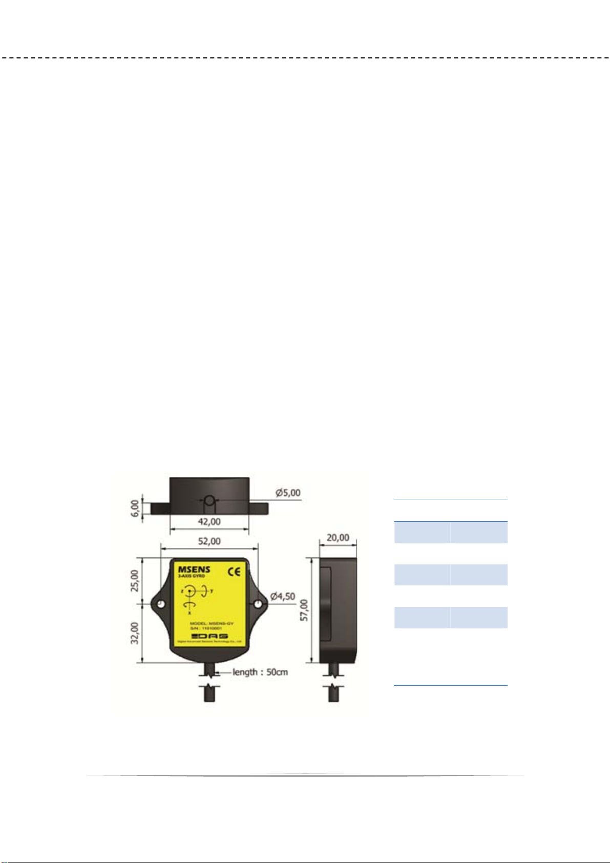
1-2Size
wire Index
RED V+
BLACK GND
GREEN 485-A(P)
WHITE 485-B(N)
YELLOW OUT
BLUE TRIGGER
Z(YAW) 값
각도 0
초기화 입력
Pic 1.1 MSENS-GY size
3
Page 4

1-3Specifications
z Measuring Range
Angle( Roll,Pitch, Yaw) : ±180 full-range
Angular velocity. ( Roll,Pitch, Yaw) : ±250, ±500, ±2000 〬/sec
z Core sensor
3-axis accelerometer & 3-axis gyro sensor
- 3 axis gyro + 3 axis accelelometer.
- Range(Roll ,Pitch, Yaw, 〬/sec) : ±250 (default)
- Bias Stability In-Run(°/hr) : < 12
- Bias Stability Over Temp(〬/sec) : <±0.5
- Scale Factor Accuracy(%) : <1
- Resolution(〬/sec) : 0.02
MSENS-GY
User’s manual
- Angle Random Walk(°/sq-rt hr) : <3
- Bandwidth(Hz) : 100
z Power
Typical : 12Vdc
The sensor was unregulated power (10~30Vdc) supply is also available.
Current : <50mA at 12Vdc
z Resolution
Gyro angular velocity : 8.75 mdps
Gyro Angle output : 0.1°
Max total error : 0.25%(FS)
z Housing
IP66, PVC Case, Water-proof Housing : The Sensor can be waterproof
silicone molding.
z OperationgTemperature
-20 to .. +85°C
z Weight
about 68g
z Cable
6P Shield cable, 50CM
4
Page 5

3-axis accelerometer & 3-axis gyro sensor
MSENS-GY
Output
2-1 2-1 RS-485 Serial output (default 115200,8,1,n)
format : Ex) [1909123494591923]54CR (’9’ is space)
[ID9MODE9X(ROLL)9Y(PITCH)9Z(YAW)]+Checksum+ CR
2-2 0~5V Voltage output. (default type)
- Yellow cable through the output.
- User can change output axis by serial command.
- Lowest range : 100mV (It can be changed between 100 ~ 1,000mV by
User’s manual
order made)
- Highest range : 4900mV (It can be changed between 4000 ~ 4900mV by
order made)
- Center Value : middle value between Low output and High output
2-3 4~20mA Current output .(order made)
- Yellow cable through the output.
- User can change output axis by serial command.
- Lowest range : 4.32mA
- Highest range : 19.68mA
- Center Value : 12mA.
5
Page 6
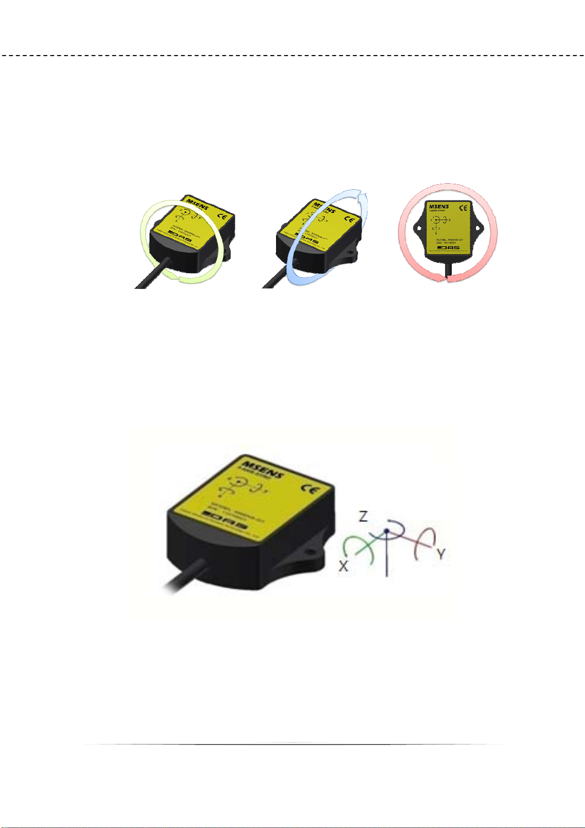
2 Sensor axis directions
MSESE-GY measures 3-axis gyro sensor (Roll, Pitch, Yaw).
3-axis directions are following.
Y ( Pitch ) Z ( Yaw )
3-axis accelerometer & 3-axis gyro sensor
X (Roll )
MSENS-GY
User’s manual
Pic .3-1 Each axis direction
Pic .3-2 3-axis directions
6
Page 7
3 Wiring
MSESE-GY for a six-stranded shielded cable is used. Supply voltage 2-line, RS-485
2-line, mA output consists of a line. RS-485 and the unused line of mA output
does not touch the other by cutting the cable must be insulated. When using RS-
485 distance is longer than 50M 120 Ohm termination is recommended. In
addition, if multiple sensors connected in parallel to use in the termination
resistors.
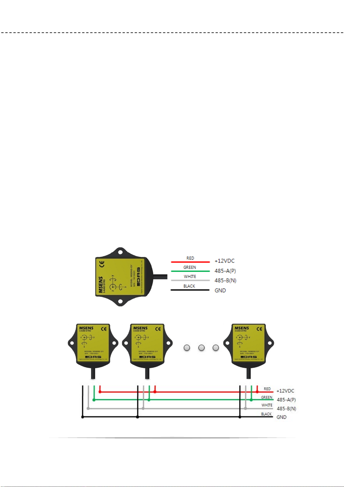
3-1RS-485 Wiring.
3-axis accelerometer & 3-axis gyro sensor
RS-485 communications can be read sensor value when the one or more
sensors can be connected in parallel to a line. However, caution this time, each
MSENS-GY
User’s manual
sensor's ID to be different, continuous data read (# READ) instruction, such as ID
and to answer all the sensors, regardless of instruction should not be used. And
when you use multiple sensors to allow sufficient power supply wiring should be
designed.
Pic 4.1 Cable Index
7
Page 8

3-axis accelerometer & 3-axis gyro sensor
Pic 4.2 RS-485 Parallel connection diagram
MSENS-GY
User’s manual
3-2 Analog Wiring
The analog output is voltage(default) or current output.
Output axis of analog is changed by user command. The default output axis is
Yaw.
(mV) out
Pic 4.3 3 Analog of voltage wiring
V
GND
A
Pic 4.4 Analog of current wiring
Acceleration VS Voltage output
GND
8
Page 9

3-axis accelerometer & 3-axis gyro sensor
4MSENS-GY Communication Commands
First of all the transfer of 'CR' will be sent by appending.
Example> In case ID = 1 , MODE = 0,
Send format : <1 Command> + Check-sum + CR
Receive format : [1 0 “Pich”“Roll”“Yaw”] + Check-sum + CR
Example of calculation checksum)
<1 START> = ‘<‘ XOR ‘1‘ XOR ‘‘ XOR ‘S’ XOR ‘T’ XOR ‘A’ XOR ‘R’ XOR ‘T’ XOR ‘>’
= CHECK_SUM
MSENS-GY
User’s manual
Data
OutPut
Set-up
command
Command Echo CMD VALUE Function Data output
<1> x x 1time data
<1 START> [1 START] x Continues
data
<1 STOP> [1 STOP] x Stop output
<1 ID 254> [1 ID 254] 1~254 ID Change
<1 SPEED 1> [1 SPEED 0] 1, 2, 3 baudrate
<1 MODE 0> [1 MODE 0] Angle:0,
angular
MODE
change
velocity :1
<1 SCALE 1> [1 SCALE 1] GY: 1,2,8
AC: 2,4,8
<1 ANALOG 2> [1 ANALOG 2] X:0, Y:1, Z:2
<1 OFFSET 3.5> [1 OFFSET 3.5]
Voltage(mV) Analog output
<1 SPAN 1.05> [1 SPAN 1.05] Scale
Factor
Full Scale
Setting
Analog 출력
축 설정
axis offset
Analog output
span
[1 0 1234 45 4567]
[1 0 1234 45 4567]
<1 CALI> [1 CALI 12 34 56] x Gyro Bias
Calibration
<1 INIT> [1 INIT] x
<1 SAVE> [1 SAVE] x
<1 RESTORE> [1 RESTORE] x
<1 VER> [1 VER MSENS-GY 01.00] x
Set to YAW 0
Save Setting
Default setting
values return
Version
information
9
Page 10

3-axis accelerometer & 3-axis gyro sensor
Table 5.1 Command
4-1 One-time data output
COMMAND <1>
Function One-time data output
Example (id=1) <1>
Echo N/A
Output [1 0 1234 45 1923]
Attention) All of following example is for ID 1, MODE 1.
Mode ’0’
Output data is applied Kalman filler. It is good for slow measurement and more correct
value.
Unit is mg/DIGIT. ex) 1234 = 1234 mg = 1.234 g
MSENS-GY
User’s manual
[10123445 1923] ÅID=1, MODE=0, X=1234, Y=45, Z=1923
Mode ‘1’
Output data is not applied Kalman filler. It is good for fast and more roughly
measurement.
Unit is mg/DIGIT ex) 1234 = 1234 mg = 1.234 g
Output is include scale value.
[1 11 522 2345 1253]Å ID=1, MODE=1 ,SCALE=1,X=522, Y=2345, Z=1253
(Attention) When the Mode is ‘1’, output interval is 10msec.
10
Page 11

3-axis accelerometer & 3-axis gyro sensor
MSENS-GY
User’s manual
4-2 Continuously data output
COMMAND <1 START>
Function Continuously data output
Example (id=1) <1 START>
Echo [1 START]
Output(mode=0) [1 0 1234 45 1923]
After send command, send the save command. If don’t send save command, lost
command when turn off.
Attention) Do not send ‘START’ command to more 2 device with RS485.
4-3 Stop data output
COMMAND <1 STOP>
Function Stop data output
Example (id=1) <1 STOP>
Echo [1 STOP]
If output speed is high, Send ‘STOP’ command several times until data output is stop.
11
Page 12

3-axis accelerometer & 3-axis gyro sensor
MSENS-GY
4-4 ID Setting
COMMAND <1 ID “New ID”>
Function ID Setting and check
Default 1
Example (new id=123) <1 ID 123>
Echo [1 ID 123]
MSENS-GY has own ID number (1~254). Default ID number is ‘1’.
You want know ID number, do following
Connect to pc on RS45
and send <0>. The return value is ID,, MODE , X,Y,Z.
User’s manual
[1 0 1234 45 1923]
It mean is ID=1 , MODE=0, X=1234, Y=45, Z=1923
(Attention) After send command, send the save command. If don’t send save command,
lost command when turn off.
12
Page 13

3-axis accelerometer & 3-axis gyro sensor
MSENS-GY
User’s manual
4-5 Data output type setting
COMMAND <1 MODE “VALUE”>
Function Data output type setting
Value 0 , 1
Default 0
Example (new MODE=1) <1 MODE1>
Echo [1 MODE1]
It is setting data output type and check.
Default value of MODE is ‘0’
MODE 0 : Output data is applied Kalman filler. It is good for slow measurement and
more correct value.
MODE 1 : Output data is not applied Kalman filler. It is good for fast and more roughly
measurement.
If you wand know what is the set MODE, Send <1 MODE>. Then return value is [1
MODE 0]. It mean is MODE 0.
4-6 Full Scale Setting
COMMAND <1 SCALE “VALUE”>
Function Full Scale Setting
Value 1, 2, 8
Default 1
Example (NEW SCALE=8) <1 SCALE 8>
Echo [1 SCALE 8]
It is to set full scale of gyro sensor and check.
13
Page 14

3-axis accelerometer & 3-axis gyro sensor
SCALE DPS
1 ±250
2 ±500
8 ±2000
Default value is 1(±250 DPS)
If you want know what is SCALE value, send <1 SCALE>
Return value is [1 SCALE 8]. It means the scale value is 8(±2000 DPS)
Output unit is always mdps.
MSENS-GY
User’s manual
4-7Data output interval
COMMAND <1 INTERVAL “VALUE”>
Function Data output interval
Value 10 ~ 1000
Default 100
Example (INTERVAL=10mS) <1 INTERVAL 10>
Echo [1 INTERVAL 10]
It is setting data output interval and check.
The setting unit is msec. Range is from 10[msec] to 1000[msec].
Setting step is 10[msec].
Default value is 100 [msec.
But, interval is only 10[msec] when MODE 1.
Send Command : <1 INTERVAL>
Return value : [1 INTERVAL 10] It mean is 10[msec].
14
Page 15

3-axis accelerometer & 3-axis gyro sensor
MSENS-GY
User’s manual
4-8Baudrate of serial
COMMAND <1 SPEED “VALUE”>
Function RS485 Baudrate of serial
Value 1, 2, 3
Default 1
Example (SPEED=2) <1 SPEED 2>
Echo [1 SPEED 2]
It is setting baudrate of RS485 and check..
Default value is Baudrate:115200, Data bit:8, Stop bit:1, parity:None
SPEED BAUD RATE
1 115200
2 57600
3 38400
If you wand know what is baudrate value, send <1 SPEED >.
Return value is [1 SPEED 1]. It mean is 115200(baudrate is 115200).
4-9Axis of analog output setting
COMMAND <1 ANALOG “VALUE”>
Function Axis of analog output setting
Value 0, 1, 2
Default 2
Example (ANALOG=0) <1 ANALOG 0>
Echo [1 ANALOG 0]
It is setting axis of analog output and check.
15
Page 16

3-axis accelerometer & 3-axis gyro sensor
Default value is 2(Yaw axis).
ANALOG AXIS
0 X (ROLL),
1 Y (PITCH)
2 Z (YAW)
If you want know what is output axis of analog. Send <1 ANALOG>.
Return value is [1 ANALOG 0].
z Analog value is deferent depend on FULL SCALE.
±2g : -2g : 0.5V, 0g : 2.5V, +2g : 4.5V 출력.
±8g : -8g : 0.5V, 0g : 2.5V, +8g : 4.5V 출력
4~20 mA : 0.5V = 5.6 mA, 2.5V = 12 mA, 4.5V = 18.4 mA
MSENS-GY
User’s manual
4-10Analog output offset setting
COMMAND <1 OFFSET“VALUE”>
Function Analog output offset setting
Value Real
Default 0
Example (OFFSET=3.5) <1 OFFSET 3.5>
Echo [1 OFFSET 3.5]
It is setting for analog output offset and check.
Default value is 0[mV].
It has two kind of type. One of them is voltage, other one is current. It is setting by
order made. Default is voltage.
If sensor is current output type and setting value is 1, output is change to 3.2uA up.
Example) <1 OFFSET 3.5>Å 3,5mV up.
<1 OFFSET -12.5>Å -12.5mV down.
16
Page 17

3-axis accelerometer & 3-axis gyro sensor
If you want know what is offset setting value, send <1 OFFSET>.
Return value is [1 OFFSET -12.5]. It means offset setting value is -12.5 mV.
MSENS-GY
User’s manual
4-11 Span of analog output setting
COMMAND <1 SPAN“VALUE”>
Function Span of analog output setting
Value Real
Default 1
Example (SPAN=1.00452) <1 SPAN1.00452>
Echo [1 SPAN1.00452]
It is setting for span of analog (mV or mA) output and check.
Default value is 1.
Example)
<1 SPAN 1.00452>Å Voltage output is FULL SCALE * 1.00452
<1 SPAN 0.9987>Å Voltage output is FULL SCALE * 0.9987
If you wand know what is SPAN setting value, Send <1 SPAN.
Return value is [1 SPAN0.9987
4-12GyroBiasCalibration
COMMAND <1 CALI >
Function Gyro Bias Calibration
Example <1 CALI>
Reply [1 CALI 123 24 43]
It is to calibration for bias of core gyro sensor
It needs about one second.
Do not change except if you know this function well.
Return value is [1 CALI123 24 43]. It means X-bias : 123 , Y-bias : 23 , Z-bias : 43
17
Page 18

3-axis accelerometer & 3-axis gyro sensor
MSENS-GY
User’s manual
4-13Z(Yaw) 0 Degree Initial Setting
COMMAND <1 INIT>
Function 1-1Z(Yaw) 0 Degree Initial Setting
Example <1 INIT>
Echo [1 INIT]
It is to change the value of angle of Yaw to 0.
It is same that the blue-line is connected red-line(+V) very sort time.
4-14Save setting values
COMMAND <1 SAVE>
Function Save setting values
Example <1 SAVE>
Echo [1 SAVE]
It is to save to EEPROM setting values.
4-15Conform the S/W version
COMMAND <1 VER>
Function Conform the S/W version
Example <1 VER>
Reply [1 VER MSENS-GY 01.00]
If you want know what is S/W version, send <1 VER>
Return value is [1 VER MSENS-AC 01.0].
4-16Return all setting values to default
18
Page 19

COMMAND <1 RESTORE>
Function Return all setting values to default
Example <1 RESTORE>
All setting values in EEPROM are return to default except baudrate.
5 Install PC Program
5-1Download pc program
The setup program is technical board of website( http://www.das-co.com).
5-2 Install
3-axis accelerometer & 3-axis gyro sensor
Echo [1 RESTORE]
MSENS-GY
User’s manual
z Double click the icon of setup.
z Input the install path.
19
Page 20

3-axis accelerometer & 3-axis gyro sensor
z Finish
6 MSENS-Viewer Main window
6-1MAIN
z MSENS-AC
MSENS-GY
User’s manual
z MSENS-GY
20
Page 21

3-axis accelerometer & 3-axis gyro sensor
MSENS-GY
User’s manual
If you want more information about program, please see the
manual of MSENS-Viewer.
The information contained in the product manual without prior notice for
quality improvement.
Described above are subject to change copyright of all content on DAS
CO.,LTD
And reproduced without prior consent, and may not be distributed by.
21
Page 22

3-axis accelerometer & 3-axis gyro sensor
MSENS-GY
User’s manual
WARNING: Shock hazard - Do Not Open.
Mains Plug or Direct plug-in adapter is used as disconnect device and it should remain readily operable
during
intended use. In order to disconnect the apparatus from the mains completely, the Mains Plug or Direct
plug-in adapter should be disconnected from the mains socket outlet completely.
WARNING: TO REDUCE THE RISK OF
ELECTRIC SHOCK, DO NOT REMOVE
COVER (OR BACK). NO USER-
SERVICEABLE PARTS INSIDE. REFER
SERVICING TO QUALIFIED SERVICE
PERSONNEL.
The lightning lash with arrowhead symbol, within
an equilateral triangle, is intended to alert the user
to the presence of uninsulated "dangerous voltage"
within the product's enclosure that may be of
suficient magnitude to constitute a risk of electric
shock to persons.
Tlie exclamation point within an equilateral triangle
is intended to alert tlie user to the presence of
important operating and maintenance (servicing)
instructions in the literature accompanying the
appliance,
FCC Warnings
WARNING: Changes or modiications to this unit not expressly
approved by the party responsible for compliance could void the
user's authoity to operate the equipment.
NOTE: This equipment has been tested and found to comply with
the limits for a Class B digital device, pursuant to Pat 15 of the FCC
Rules. These limits are designed to provide reasonable protection
against harmful interference in a residential installation. This
equipment generates, uses, and can radiate radio frequency energy
and, if not installed and used in accordance with the instructions,
may cause harmful interference to radio communications. However,
there is no guarantee that interference will not occur in a particular
installation. If this equipment does cause harmful interference to
radio or television reception, which can be determined by turning
the equipment off and on, the user is encouraged to try to correct the
interference by one or more of the following measures:
• Reorient or relocate the receiving antenna.
• Increase the separation between the equipment and receiver.
• Connect the equipment into an outlet on a circuit different rom
that to which the receiver is connected.
• Consult the dealer or an experienced radio/TV technician for help.
22
Page 23

3-axis accelerometer & 3-axis gyro sensor
MSENS-GY
User’s manual
Additional Warnings
The apparatus shall not be exposed to dripping or splashing and that no objects filled with liquids,
such as vases, shall be placed on apparatus.
L'appareil ne doit pas itre exposi aux ecoulements ou aux edaboussures etaucun objetne
contenantdeliquide, tel qu'un vase, ne doit itre place sur I'objet.
Battery shall not be exposed to excessive heat such as sunshine, fire or the like.
Les piles ne doiventpas itre exposees a de.forte chaleur,
tel qu'a la lumiere du soleil, au feu ou autres choses de
semblable.
Caution marking is located at the rear or back of the apparatus.
Attention marquageestsituea I'arriereou a I'arriere de l'appareil
The marking information is located at the rear or back of apparatus.
Les informations de marquage est situe a I'arriere ou a I'arriere de l'appareil.
DAS Co., Ltd
Copyright ⓒ by Das Co.,Ltd. All Right Reserved
Website : www.das-co.com
Phone No : +82 - (0)31 - 356 - 3541
FAX No : +82 - (0)31 – 356 - 3572
e-mail : jastech@hanmail.net
Address : 09-3, Yangno-ri, Bibong-myeon, Hwaseong-si, Gyeonggi-do, Korea
[445-842]
23
 Loading...