

Page 1

Rigging Manual
convert 15A series
El colgado del equipo sólo debe realizarse
utilizand o los herrajes de col gado
recomendados y por personal cualificado.
No cuelgue la caja de las asas.
The appliance should be flown only from
the rigging points and by qualified
personnel. Do not suspend the box from
the handles.
Page 2

CONTENTS
RIGGING SYSTEM
VERTICAL ARRAY FOR “-RA” VERSIONS
HORIZONTAL ARRAY FOR “-RA” VERSIONS
VERTICAL ARRAY FOR “-A” VERSIONS
HORIZONTAL ARRAY FOR “-A” VERSIONS
3 a 4
5 a 8
9 a 12
13 a 16
17 a 19
Manual de Colgado / convert 15A series / Rigging Manual
Page 3

RIGGING SYSTEM
Warning
This manual contains needed information for
flying D.A.S. Audio line array systems, description
of the elements and safety precautions. To perform
any operations related to flying the system, read
the present document first, and act on the
warnings and advice given. The goal is to allow the
user to become familiar with the mechanical
elements required to fly the acoustic system, as
well as the safety measures to be taken during
set-up and teardown.
Only experience installers with adequate
knowledge of the equipment and local safety
regulations should fly speaker boxes. It is the
user´s responsibility to ensure that the systems to
be flown (including flying accessories) comply with
state and local regulations.
The working load limits in this manual are the
results of tests by independent laboratories. It is
the user´s responsibility to stay within safe limits. It
is the user´s responsibility to follow and comply
with safety factors, resistance values, periodical
supervisions and warnings given in this manual.
Product improvement by means of research and
development is on going at D.A.S. Specifications
are subject to change without notice.
When a system is flying, the working load must
be lower than the resistance of each individual
flying point in the enclosure, as well as each box.
Hanging hardware should be regularly inspected
and suspect units replaced if in doubt. This is
important to avoid injury and absolutely no risks
should be taken in this respect. It is highly
recommended that you implement an inspection
and maintenance program on flying elements,
including reports to be filled out by the personnel
that will carry out the inspections. Local
regulations may exist that, in case of accident,
may require you to prevent evidence of inspection
reports and corrective actions after defects were
found.
Absolutely no risks should be taken with
regards to public safety. When flying enclosures
from ceiling support structures, extreme care
should be taken to assure the load bearing
capabilities of the structures so that the installation
is absolutely safe. Do not fly enclosures from
unsafe structures. Consult a certified professional if
needed. All flying accessories that are not supplied
by D.A.S. Audio are the user´s responsibility. Use
at your own risk.
To this date, there is no international standard
regarding the flying of acoustic systems. However,
it is common practice to apply 5:1 safety factors
for enclosures and static elements. For slings and
elements exposed to material fatigue due to
friction and load variation the following ratios must
be met; 5:1 for steel cable slings, 4:1 for steel
chain slings and 7:1 for polyester slings. Thus, an
element with a breaking load limit of 1000 kg may
be statically loaded with 200 kg (5:1 safety factor)
and dynamically loaded with 142 kg (7:1 safety
factor).
Manual de Colgado / convert 15A series / Rigging Manual
3
Page 4

UNIVERSAL FLY BAR (UFB)
UNIVERSAL FLY BAR (UFB)
HORIZONTAL ARRAY
AXA-CV15H
AXA-CV15H
AXA-CV15
VERTICAL ARRAY
AX-CONVERT15
AX-CONVERT15B
AXA-CV15
CONVERT 1560A
CONVERT 1560RA
CONVERT 1590RA
4
Manual de Colgado / convert 15A series / Rigging Manual
CONVERT 1590A
Page 5

VERTICAL ARRAY (‘-RA’ versions)
For this mounting type convert1560RA or
convert1590RA are required. This is the simplest
way because only AX-CONVERT15 rigging
accessory is required for just one lift motor. In case
of using two lift motors, AX-CONVERT15 and PICK-
UP AX-CONVERT15 will be needed.
Be conscious that rigging must be performed
by highly skilled workers, with an adequate
knowledge of the equipment and fittings to use.
Workers must also know the local safety
regulations. User is responsible to ensure that
sound rigging systems (including rigging
accessories) meet state and local regulations in
force.
Mounting type
AX-CONVERT15
Accessories required for this mounting type
(WLL =300 kg)
Firstly, lets see how a rigging system, which is
built into the enclosure, works.
At the rear you will find a safety pin which is
not removable.
If we push the red button and pull it down, a
cog blade system is exposed. This piece will slide
out if we push a handle near the pin (see figure).
S
de
la
B
Cog
yst
Handled
m
e
PICK UP AX-CONVERT15
Pin
Ca
p
s
fo
t
o
r th
a
cc
e
o
a
m
d
m
j
acent
o
d
a
te
t
h
e s
e
n
cl
os
y
ur
s
te
e
m
Manual de Colgado / convert 15A series / Rigging Manual
5
Page 6

Junction between enclosures
Suppose we join several enclosures to create a
vertical array mounting type for ‘-RA’ versions.
We will place the first two enclosures, as in
Figure1, one above the other on a flat surface.
The rigging system ends are aligned and
prevent them from moving while acting on the
locking pins.
To join the two enclosures with the rigging
system we will act on the rear pin (shown in red in
Figure 2) and also on the lever adjacent to it.
Refer to Figure 3.
On the previous page we described the
elements of this convert 15A version.
Figure 1
Push the red button and pull it down to free
the cog blade system.
This piece will slide out if we push the lever
near the pin and act simultaneously on the pin, as
we said before.
Release the safety pin button and ensure that it
recovers its initial position to end the process (by
an internal spring as shown in Figure 4).
Repeat this process with the other pins
marked in blue in Figure 2 and the two enclosures
will join together safely.
To join one more enclosure, take the group of
two enclosures fixed before and follow the
instructions described (Figure 5 and Figure 6).
Due to the coverage angles, more than three
enclosures won´t be necessary.
Figure 2
Pin
Handled
Figure 3
Figure 4
6
Manual de Colgado / convert 15A series / Rigging Manual
Page 7

Figure 5
Remember to repeat the junction process acting on the pins marked in Figure 6. The enclosures will
remain together securely.
Figure 6
Manual de Colgado / convert 15A series / Rigging Manual
7
Page 8

Finally, join AX-CONVERT15 with the top enclosure.
First, unite each of the side parts of the AX facing the cog blade system of the side piece with the top
enclosure caps. Act on the safety pin of this side of the enclosure as we explained before (see the figures
below).
To finish, place the AX bar with the safety pins in the holes of the top part which correspond to the right
angles.
AX-CONVERT15
PICK-UP AX-CONVERT15
8
Manual de Colgado / convert 15A series / Rigging Manual
Page 9

HORIZONTAL ARRAY (‘-RA’ versions)
For this mounting type convert1560RA or
convert1590RA are required. It is very simple
because only UFB and AXA-CV15H rigging
accessories are required for just one lift motor. In
case of using two lift motors, another UFB will be
needed.
Be conscious that rigging must be performed
by highly skilled workers, with an adequate
knowledge of the equipment and fittings to use.
Workers must also know the local safety
regulations. User is responsible to ensure that
sound rigging systems (including rigging
accessories) meet state and local regulations in
force.
Mounting type
UFB
(WLL =525
kg)
Mounting type accessories required
Firstly, lets see how a rigging system, which is
built into the enclosure, works.
At the rear you will find a safety pin which is
not removable.
If we push the red button and pull it down, a
cog blade system is exposed. This piece will slide
out if we push a handle near the pin (see figure).
Blade System
Cog
Handled
AXA-CV15H
(4 screws included)
Pin
Caps for the adjacent enclosure
to accomm
odate the system
Manual de Colgado / convert 15A series / Rigging Manual
9
Page 10

Junction between enclosures
Suppose we join several enclosures to create
an horizontal array mounting type for ‘-RA’
versions.
We will place the first two enclosures, as in
Figure7, one above the other on a flat surface.
The rigging system ends are aligned and
prevent them from moving while acting on the
locking pins.
To join the two enclosures with the rigging
system we will act on the rear pin (shown in red in
Figure 9) and also on the lever adjacent to it.
Push the red button and pull it down to free
the cog blade system.
This piece will slide out if we push the lever
near the pin and act simultaneously on the pin, as
we said before.
Release the safety pin button and ensure that it
recovers its initial position to end the process (by
an internal spring as shown in Figure 10).
Repeat this process with the others pin
(marked in blue in Figure 9) and the two
enclosures will join together safely.
Figure 7
To join one more enclosure, take the group of
two enclosures fixed before and follow the
instructions described in the Figure 11.
Pin
Figure 8
Handled
Figure 9
10
Figure 10
Figure 11
Manual de Colgado / convert 15A series / Rigging Manual
Page 11

In the Figure 12 we can see the mounting of
three enclosures.
We should add more enclosures in the same
way to the desired units.
Also, we can choose to mount systems onto
SUBs as shown in Figure 13.
Figure 12
Figure 13
If we choose a rigging mounting type, after joining the enclosures place the AXA-CV15H and the UFB (one
or two depending on the lift motors).
M10x70 screws (included with accessory)
AXA-CV15H
For mounting sets of one or two enclosures
the use of a UFB is not required leaving the set as
shown in the figures on the right.
For more than two enclosures we will add one
or two UFB for the lift motors.
Manual de Colgado / convert 15A series / Rigging Manual
11
Page 12

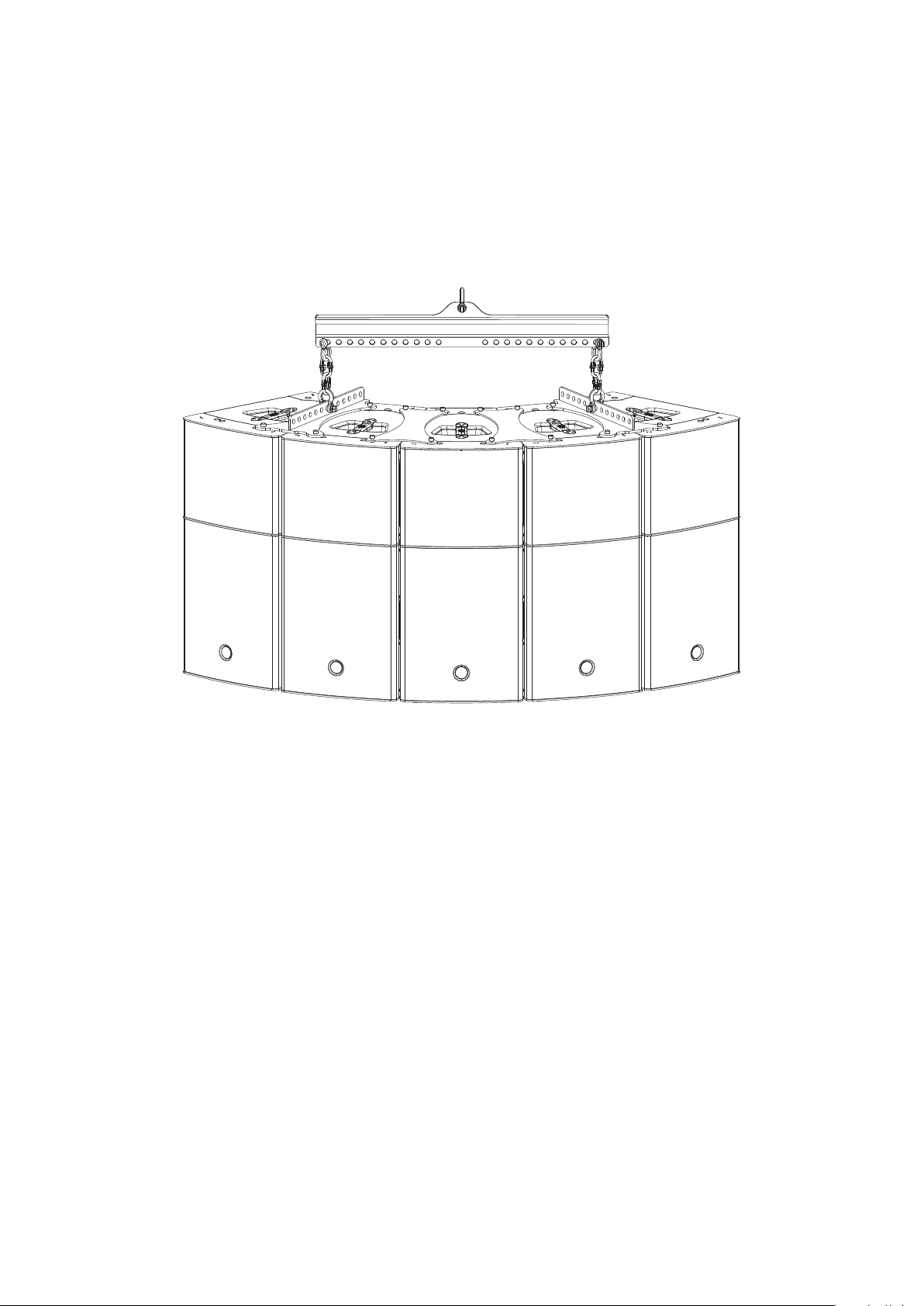
Next, for two or more enclosure sets the different mounting positions of AXA-CV15H are shown.
3 enclosure mounting
4 enclosure mounting
5 enclosure mounting 6 enclosure mounting
The use of the UFB will result as shown below.
If two lift motors are used, add another UFB.
12
Manual de Colgado / convert 15A series / Rigging Manual
Page 13

VERTICAL ARRAY (‘-A’ versions)
This mounting type convert1560A or
convert1590A are required. Some AXA-CV15 and
one AX-CONVERT15B for one lift motor. In case of
using two lift motors, a PICK UP AX-CONVERT15 will
be needed.
Be conscious that rigging must be performed
by highly skilled workers, with an adequate
knowledge of the equipment and fittings to use.
Workers must also know the local safety
regulations. User is responsible to ensure that
sound rigging systems (including rigging
accessories) meet state and local regulations in
force.
Mounting type
AX-CONVERT15B
(WLL=300 kgf)
(4 screws included)
Firstly, place two enclosures like in Figure 14,
one above the other on a flat surface.
Remove the screws indicated in Figure 14.
Following, screw the AXA-CV15 with the
included screws in the same position shown in
Figure 15.
The final result is shown in Figure 16.
AXA-CV15
PICK UP AX-CONVERT15
(WLL=300 kgf)
Figure 14
Figure 15
Manual de Colgado / convert 15A series / Rigging Manual
Figure 16
13
Page 14

Repeat the process on the other side of the
enclosures (Figure 17 and Figure 18).
If we don´t mount the third enclosure we will
mount the AX-CONVERT15B and, in this case, we
will follow the instructions shown in Figures 19 to
22.
Given the coverage angles, more than three
enclosures won´t be needed.
Figure 17
Figure 18
14
Figure 20Figure 19
Figure 21 Figure 22
Manual de Colgado / convert 15A series / Rigging Manual
Page 15

Now, mount the side parts of the AX-CONVERT15B like the next figures show.
Figure 24Figure 23
Figure 25
Figure 26
After that, if we are going to rig the system with one lift motor, we will mount the AX-CONVERT15B
crowbar like the next figures show.
Figure 27 Figure 28
Manual de Colgado / convert 15A series / Rigging Manual
15
Page 16

If we rig the system with two lift motors mount the AX-CONVERT15B crowbar and a PICK UP AXCONVERT15B like the next figures show.
Figure 29
Figure 30
16
Manual de Colgado / convert 15A series / Rigging Manual
Page 17

HORIZONTAL ARRAY (‘-A’ versions)
This setup is composed of convert 1560A or
convert 1590A and is the most complex because it
requires a preview planification. The following
rigging accessories are required: UFB, AXA-CV15
and AXA-CV15H. In case of using two lift motors,
another UFB will be needed.
Be conscious that rigging must be performed
by highly skilled workers, with an adequate
knowledge of the equipment and fittings to use.
Workers must also know the local safety
regulations. User is responsible to ensure that
sound rigging systems (including rigging
accessories) meet state and local regulations in
force.
Mounting type
UFB
525 kg)
(WLL =
Mounting type accessories required
It is very important to place the pieces in the correct position as the figures show depending on the
number of enclosures you need.
Use the screws provided with the AXA. Make sure the screws are securely tightened.
The use of security gloves and shoes are highly recommended for heavy object operations.
AXA-CV15H
(4 screws included)
AXA-CV15
(4 screws included)
1 enclosure mounting
Manual de Colgado / convert 15A series / Rigging Manual
2 enclosure mounting
17
Page 18

3 enclosure mounting 4 enclosure mounting
5 enclosure mounting
(max. recommended)
Also, we can choose to mount systems onto SUBs
like the figure on the right shows.
In this case secure the enclosures to prevent tipping.
18
Manual de Colgado / convert 15A series / Rigging Manual
Page 19
If we choose the rigging mounting we will have to mount a UFB for one lift motor. If we use two motors,
another UFB will be needed.
In both cases, the maximum recommended number of enclosures for this set is 5 units.
Be conscious that rigging must be performed by highly skilled workers, with an adequate knowledge of
the equipment and fittings to use. Workers also must know the local safety regulations. User is responsible to
ensure that sound rigging systems (including rigging accessories) meet state and local regulations in force.
Manual de Colgado / convert 15A series / Rigging Manual
19
Page 20

www.dasaudio.com
RM_CV15_01_EN
D.A.S. AUDIO, S.A.
C/. Islas Baleares, 24
46988 Fuente del Jarro
Valencia, SPAIN
Tel. 96 134 0525
Tel. Intl. +34 96 134 0860
Fax 96 134 0607
Fax Intl. +34 96 134 0607
D.A.S. AUDIO OF AMERICA, INC.
Sunset Palmetto Park
6816 NW 77th Court.
Miami, FL. 33166 - U.S.A.
TOLL FREE: 1-888DAS4USA
Tel. +1 305 436 0521
Fax +1 305 436 0528
D.A.S. AUDIO ASIA PTE. LTD.
25 Kaki Bukit Crescent #01-00/02-00
Kaki Bukit Techpark 1
Singapore 416256
Tel. +65 6742 0151
Fax +65 6742 0157
 Loading...