


CONTROLS
Instruction Manual
Signal Conditioner/Generator
P.O. Box 10
5000 W. 106th Street
DP10 CONTROL SERIES
LT168 (0318)
Zionsville, Indiana 46077
Phone (317) 873-5211
Fax (317) 873-1105
www.dartcontrols.com
A-5-4023E

Table of Contents
Introduction ....................................................................................................................................... 2
General Features .............................................................................................................................. 2
Models & Options ............................................................................................................................. 2
Specifications ................................................................................................................................... 3
DP10 Electrical ............................................................................................................................. 3
DP10 Mechanical ......................................................................................................................... 3
Environmental ............................................................................................................................... 3
Mechanical Installation .................................................................................................................... 4
Exploded Panel View .................................................................................................................... 4
Cut-out and Mounting Dimensions ............................................................................................... 4
Installation & Diagrams .................................................................................................................... 5
P3 Terminal Block Hook-Up Diagram ........................................................................................... 5
P3 Terminal Block Descriptions .................................................................................................... 5
Basic Operating Information ........................................................................................................... 6
Visual Reference .......................................................................................................................... 6
How to Change a Parameter's Value (The Short Story) ............................................................. 7
Operating the User Interface (The Long Story) .......................................................................... 7
Device Configuration .................................................................................................................... 8
Mode of Operation ........................................................................................................................ 8
Software Parameters ................................................................................................................... 9
Parameter Descriptions ............................................................................................................ 10
Troubleshooting .............................................................................................................................. 14
Technical Support Options ............................................................................................................... 14
What's Special About www.dartcontrols.com? ................................................................................. 14
1

Introduction
The DP10 is a panel mounted, multi-purpose signal conditioner that allows the operator easy access
to make adjustments to system operations. The DP10 may be used in OEM equipment designs, plant
operation or laboratory applications. Most other signal conditioners are DIN rail mounted inside a panel
and designed to be set up once - many applications require frequent adjustments to meet application
needs. The DP10's unique front-panel design addresses this by making output adjustment easily
accessible via convenient up and down pushbuttons with a large, easy to read LED display.
General Features
- Microprocessor design digital accuracy and repeatability
- Digital design offers long-term stability in a variety of environments
- Dual-Mode operation: Signal Scaling, or Signal Generation
- Works in either voltage or Current output modes - PWM voltage (1kHz - 100kHz) Optional
- Universal power supply accepts supply voltages of 85-265VAC @ 50-60Hz without switches or
jumper settings.
- Transient voltage protection protects device in harsh industrial environments
- 1/8 DIN panel mount is rated up to NEMA 4X in similarly rated panel
- Large 4 digit, 1/2” LED display is easy to read in indoor or outdoor applications
- Euro style terminal strip standard - pluggable terminal strip optional
- Wide operating temperature -10C to +45C (14F to 113F)
- Jumper selectable signal type - Voltage or Current (mA) signal
- Configurable input to lock out operator changes once set
Models & Options
Models & Options
Model
DP10 Voltage or Current (mA) signal conditioner with terminal strip
Description
2

Specifications
DP10 Electrical
Line Input Voltage ..................................................................................................... Any Voltage from 85-265 VAC
Line Input Frequency .................................................................................................... Any Freq. from 48-62 Hertz
Voltage Signal Input ....................................................................................................... 0-5 VDC (Optional Higher)
Voltage Signal Output ..................................................................... 0.1-5VDC MIN; 0.1-20 VDC MAX; 10mA MAX
mA Signal Input ........................................................................................................................................... 4-20mA
mA Signal Output ........................................................................................................................................ 4-20mA
Display Range ........................................................................................................................... Default: 0 – 100.0%
................................................................................................................................ Maximum: ‘-9999’ – ‘9999’
Units of Operation ............................................................................................................................. programmable
Onboard Power Supply (Externally Accessible) .................................................................................... 5V @ 500Ma
Voltage Regulated Supply Output Range ............................................................... Default: 24VDC +/-5%; 200mA
Customer Specific Option Available (Regulated) .............................................. 5VDC/50mA – 20VDC/200mA
DP10 Mechanical
Display Type .................................................................................................................LED, Red, 4 Digit, ½” Height
Housing Type (with supplied gasket in NEMA 4X panel) ............................................................... 1/8 DIN NEMA 4X
Connector Style .........................................................................................................3.5mm & 5mm European Style
Terminal Block Torque Setting ................................................................................................ 4.4 in. lb. Max or .5Nm
Faceplate Material ............................................................................................... Polycarbonate with Lexan Overlay
Housing Material ........................................................................................................................................Aluminum
Length (Required Panel Depth) .................................................................................................... 4.625”, 117.48mm
Faceplate Width ........................................................................................................................... 4.539”, 115.29mm
Weight DP10 .................................................................................................................... 0.900 lb, 14.4 oz, 408.22g
Environmental
Operating Temperature Range ........................................................................................ -10C to 45C (14F to 113F)
Operating Humidity Range ..................................................................................................... 95%, non-condensin
g
3

Mechanical Installation
5.000"
4.625"
2.289"
1.656"
Tach
Item
ValuPage
Tach
Item
ValuPage
3.622"
HOUSING DEPTH
4.625"
PANEL CUT-OUT
1.770"
DP10
MICRO-DRIVE
SIGNAL CONDITIONER
ENTER
CONTROLS
4.000"
4.000"
.140" x 2
0.885"
GEN
SCL
SPL
PANEL MOUNTING GASKET
(WITH THE ADHESIVE SIDE OF
GASKET FACING THE CUSTOMER
MOUNTING PANEL)
CUSTOMER
MOUNTING PANEL
(HOLE CUT-OUT FOR CONTROL
HOUSING APPROXIMATELY
3.622" WIDE BY 1.770" HIGH)
DP10
CONTROL
SUPPLIED WITH EACH CONTROL:
1) GASKET
2) (2) 6-32 X 3/4 PANHEAD BLACK OXIDE STAINLESS SCREWS
3) (2) #6 NUT WITH LOCKWASHER
Exploded Panel View
Cut-out and Mounting Dimensions
Figure 1
Figure 2
4

Installation & Diagrams
AC INPUT
AC INPUT
P3-1
P3-2
P3-3
P3-4
P3-5
P3-6
P3-7
P3-8
DP10
2 AMP
P3-9
P3-10
P3-11
P3-12
}
85-265VAC
N
L
+5V
COM
IN2
IN1
4-20 OUT (+)
4-20 OUT (-)
V-OUT (+)
V-OUT (-)
SIGNAL IN (+)
SIGNAL IN (-)
+V_USER
-V_USER
+24VDC SUPPLY -24VDC SUPPLY
}
OUTPUT TO USER DEVICE
JP5
JP4
JP3
JP1
P3 Terminal Block Hook-Up Diagram
Figure 3
P3 Terminal Block Descriptions
P3-1 (AC / N) – For single phase AC lines connect the Neutral side of your AC line to this terminal.
For systems with two hot AC lines, connect either of the Hot AC lines to this terminal.
P3-2 (AC / L) – For single phase AC lines connect the Hot side of your AC line to this terminal. For
systems with two hot AC lines, connect either of the Hot AC lines to this terminal.
P3-3 (-SIGNAL IN) – In Scaled Mode, connects to Negative or Common of voltage or current signal
to be attenuated.
P3-4 (+SIGNAL IN) – In Scaled Mode, connects to Positive of voltage or current signal to be attenuated.
P3-5 (-24VDC SUPPLY) – A 24VDC* supply output is provided to the user for sensor or other device.
P3-6 (+24VDC SUPPLY) – A 24VDC* supply output is provided to the user for sensor or other device.
P3-7 (-mA OUTPUT) – The negative connection for either Scaled or Generated mA current output
signal.
P3-8 (+mA OUTPUT) – The Positive connection for either Scaled or Generated mA current output
signal.
P3-9 IN1 - Contact input for user configurable actions such as specified output, and set point lock.
P3-10 IN2 - Contact input for user configurable actions such as specified output, and set point lock.
P3-11 COM
P3-12 +5V
* Note: An optional Voltage Regulator for 5-20V is available for customer use. Current capability depends on voltage required; e.g.
5V/50mA to 20V/200mA; thermally current limited.
5

Basic Operating Information
Tach
Item
ValuPage
Tach
Item
ValuPage
MICRO-DRIVE
SIGNAL CONDITIONER
ENTER
CONTROLS
Display Window
Up & Down Buttons
ENTER (Select) Button
GEN
SCL
SPL
The DP10 Signal Conditioner is a panel-mounted multiple function device used to either attenuate
(scale or reduce), convert, or generate control signals typically used in laboratory/R&D or plant/industrial
applications. The input signals are analog in nature and specifically in the 0-5VDC or 4-20mA range.
The output signal can be either 4-20mA or from 0.1Vdc to the Vset voltage (5-20VDC).
Visual Reference
The Up/Down buttons are used to Scale or Set the output level, in percent (default). The Minimum
Scaling/Generator output is 0.0%. The Maximum Scaling/Generator output is 100.0%. On power up,
the factory default setting is "Last Value".
When lit, the annunciator LED’s across the top of the DP10 indicate the following:
SCL: Scaling mode is active and depending on jumper configuration, either a current or voltage will be
output. In current output mode the Display setting and the input Current or Voltage effects the 4-20mA
output. In Voltage output mode the Display setting, the maximum level set by the potentiometer R9
adjustment and the input Current or Voltage effects the output Voltage level; see appropriate sections
for proper hardware and software setup.
Gen: Generate mode is active and depending on jumper configuration, either a current or voltage will
be output. In Current output mode only the Display setting effects the 4-20mA current output. In Voltage
output mode, the Display setting and the maximum level set by the potentiometer R9 adjustment
determine the output level; see appropriate sections for proper hardware and software setup.
SPL: The DP10 is in Set Point Lock; this effectively disables any changes until IN1/IN2 input levels
change according to the functional configurations. Various modes are available with SPL, please see
appropriate sections for proper setup.
Figure 4
6

How to Change a Parameter's Value (The Short Story)
1. Hold down the Enter button until Parameter-Selection Mode is entered (Parameter 'P 0'
Displayed)
2. Using the Up and Down buttons, select the desired parameter number to view or edit
3. Press the Enter button to change the value of the parameter
4. Using the Up and Down buttons, change the parameter's value as desired
5. Press the Enter button to permanently save the changes (Return to Parameter-Selection Mode)
6. Select parameter zero and press the Enter button to return to Running Mode
Operating the User Interface (The Long Story)
The LED display has three basic operating modes: Running Mode, Parameter-Selection Mode,
and Value Mode. Each of the three modes have specific visual indicators that allow the user to
immediately determine the current state or mode of the user interface. Parameter-Selection Mode
and Value Mode can only be entered if the Program Enable jumper is in the 'P/EN' position.
Running Mode is the default display of the unit when power is applied. The display shows the
target value in the appropriate user-defined format. The Up and Down buttons increase or decrease
the displayed target value until either the display minimum or display maximum limit is reached.
Parameter-Selection Mode can be entered by simply pressing and holding the Enter button down
for three seconds. Once in Parameter-Selection Mode, the far left of the display will be a ‘P’. The
right side of the display will indicate the currently selected parameter number for editing purposes.
Pressing the Up or Down button will increase or decrease the selected parameter number on the
display. Although the parameter numbers are in numerical order, some numbers are skipped.
These skipped numbers represent reserved parameters that are not yet implemented and are
not displayed. Once the desired parameter number is displayed, a press of the Enter button will
change the display to the Value Mode.
Value Mode is used to modify the value of the selected parameter. When in Value Mode, the
two dots which form the colon between digits two and three, will alternately flash (one, then the
other.) Pressing the Up or Down button increases or decreases the selected parameter’s value.
See the Software Parameters for a list of allowable values and ranges. Value changes take effect
immediately. Once the desired value is showing in the display window, pressing the Enter button
again will return to Parameter-Selection Mode. The new value is not saved in permanent memory
until the Enter button is pressed. Removing power from the unit while in Value Mode may result
in the specified new value being lost.
The front panel Annunciators will be perform as follows:
Parameter 10 = 1; ‘Gen’ annunciator lit
Parameter 10 = 2; ‘SCL’ annunciator lit
Parameter 30 = 7, IN1 = Low; ‘SCL’ annunciator lit
Parameter 35 = 7, IN2 = High; ‘SCL’ annunciator lit
7

Device Configuration
Configuration is accomplished via jumper settings and (for Voltage Outputs only) a trimpot adjustment.
Location is as follows:
P3
P6
Program Enable
(JP5)
I_IN V_IN
/4-20mA
V
OUT
Jumper 4 (JP4)
COM P/EN
Trimpot
(R9)
/4-20mA
V
OUT
Jumper 3 (JP3)
Figure 5
JP1
V_OUT
I_OUT
V_OUT
I_OUT
P5
With the display set to 100.0 and no user device connected to ‘V-OUT’, P3-5 (-) and P3-6(+), adjust
R9 for the desired maximum V-OUT. Finally, connect the user device and carefully re-adjust R9 to
trim the output to desired maximum V-OUT. This will prevent the output from exceeding the limits of
the user device if done properly. The user should evaluate what their system will be doing during this
adjustment to prevent any harmful results.
Mode of Operation
There are three Modes of Operation for the DP10, established by the JP1, JP3, and JP4 jumper settings:
1. JP1 - If the DP10 is receiving a signal to be Scaled or Converted, this setting defines the
input signal type (0-5Vdc or 4-20mA Current) (Optional high input voltage or PWM).
2. JP3 - Determines the Output Signal type - Vdc or mA Current. MUST be same type as JP4
3. JP4 - Determines the Output Signal type - Vdc or mA Current. MUST be same type as JP3
The four jumper settings allow the DP10 to operate as:
• 4-20mA Input/Scaled 4-20mA or 0.1-20Vdc Output
• 0-5Vdc Input/Scaled 4-20mA or 0.1-20Vdc Output
• No Input/Generator 4-20mA or 0.1-20Vdc Output
Note: Both JP3 and JP4 must be set correctly.
DP10Current/VoltageI/OJumpers&Parameter10Settings
Input Output Parameter10 JP1 JP3 JP4 JP5
Scale/Generate V/IIN V/IOutReference V/IOUTPowerSupply ApplicationConfiguration
PintoPinJumperConfiguration
Current Voltage Scale Ii Vo Vo
Current Current Scale Ii Io Io
Voltage Voltage Scale Vi Vo Vo
Voltage Current Scale Vi Io Io
Generate Voltage Gen N/A Vo Vo
Generate Current Gen N/A Io Io
Scale=2 AllowChange=P/ENposition
Gen=1 InhibitChange='COM'position
8

Software Parameters
Value Range
Factory
User
Parameter
0 Selecting this item exits to Running Mode n/a n/a
1 Model Number 90 – DP10 Unit 90
2 Software Build 1 – 9999 n/a
3 Hardware Version 1 – 9999 n/a
4 Serial Number – Major (reserved) n/a n/a
5 Serial Number – Minor (reserved) n/a n/a
10 Generate / Scale 1 – Generate
11 Display Intensity 0 – 31 (Dim – Bright) 26
12 Display Zero Blanking 1 – ___X Show at least 1 Digit
13 Decimal Point Position 0 – DP Disabled (XXXX)
15 Keypad Mode 1 – Linear, Constant Rate
16 Keypad Scroll Delay 0 – 30 (Fast – Slow) 10
18 Power-up Mode 1 – Default to Zero Display
19 Power-up Value 0 – 9999 (Display Units) 0
20 Display Value at Minimum Output -9999 – 9999 (Display Units) 0
21 Display Value at Maximum Output -9999 – 9999 (Display Units) 1000
25 Output % - Minimum 0 – 1000 (1/10th Percent Units) 0
26 Output % - Maximum 0 – 1000 (1/10th Percent Units) 1000
30 IN1 Input Configuration 1 – Output 0% When IN1 Low
31 IN1 Setpoint -9999 – 9999 (Display Units) 0
Input #2 (IN2) Setup
35 IN2 Input Configuration 1 – Output 0% When IN2 Low
36 IN2 Setpoint -9999 – 9999 (Display Units) 0
95 Restore Settings to Factory Default 0 – Do Nothing & Exit
98 Save to User Default Area 0 – Do Nothing & Exit
99 Restore from User Default Area 0 – Do Nothing & Exit
Read-Only Parameters
General Setup
Display & Output Setup
Input #1 (IN1) Setup
Parameter Memory Commands
Description
2 - Scale
2 – __XX Show at least 2 Digits
3 – _XXX Show at least 3 Digits
4 – XXXX Show all 4 Digits
1 – X.XXX
2 – XX.XX
3 – XXX.X
4 – XXXX.
2 – Non-linear, Accelerating Rate
2 – Default to Power-up Value
3 – Default to Previous Running Val.
2 – Output 0% When IN1 High
3 – Output Setpoint When IN1 Low
4 – Output Setpoint When IN1 High
5 – Output 100% When IN1 Low
6 – Output 100% When IN1 High
7 – Lock Set Point when IN1 is Low
(See: Parameter Description for details)
2 – Output 0% When IN2 High
3 – Output Setpoint When IN2 Low
4 – Output Setpoint When IN2 High
5 – Output 100% When IN2 Low
6 – Output 100% When IN2 High
7 – Lock Set Point when IN2 is High
(See: Parameter Description for details)
5 – Restore Factory Defaults
1 – Save Setting
1 – Restore Settings
(units)
Default
1
2
3
2
3
1
1
0
0
0
Settings
9

Parameter Descriptions
Parameter 0 – Exit to Running Mode
When parameter 0 is selected in Parameter-Selection Mode, the unit will return to Running
Mode and display the running value. This should be selected once the changes to the
parameters are completed.
Parameter 1 – Model Number (Read Only)
This is a number which represents the base model number for the product. The model
code for the DP10 is 90.
Parameter 2 – Software Build (Read Only)
The software build is a code which identifies the software version of the unit.
Parameter 3 – Hardware Version (Read Only)
The hardware version is a code which identifies which hardware was used to build the unit.
Parameter 4 & 5 – Serial Number, Major & Minor (Read Only)
These parameters are reserved for future use as an electronic serial number and are unique
to each manufactured unit.
Parameter 10 – Generate / Scale
Mode 1: Generate
Generate Output Signal
Mode 2: Scale
Scale Input Signal
Parameter 11 – Display Intensity
This parameter adjusts the intensity of the LED display digits in the front panel of the unit.
The values of 0 – 31 correspond to a gradual change from very dim to very bright.
Parameter 12 – Display Zero Blanking
This selects the number of display digits that are required to be displayed regardless of
the display value. For example, with a Display Zero Blanking setting of 3 and a displayed
value of 6, the display would show "_006".
Mode 1: ___X Always show at least 1 digit
Mode 2: __XX Always show at least 2 digits
Mode 3: _XXX Always show at least 3 digits
Mode 4: XXXX Always show all 4 digits
Parameter 13 – Decimal Point (DP) Position
This selects the format of the display with respect to the decimal point’s position. This
parameter does not affect the value entry for other parameters. For example, if the user
desires to display numbers such as 12.34 or 1.05, then parameter 13 should be set to 2.
Mode 0: Fixed XXXX (DP disabled)
Mode 1: Fixed X.XXX
Mode 2: Fixed XX.XX
Mode 3: Fixed XXX.X
Mode 4: Fixed XXXX.
Parameter 15 – Keypad Mode
This parameter selects the operating mode of the front-panel push buttons. In some
applications, increasing or decreasing the scroll rate provides the user more controllability
when entering settings. Parameters 14 and 15 affect only the Up and Down buttons when
the user interface is in Running Mode.
Mode 1: Linear, Constant Rate
In linear mode, pressing and holding the Up or Down buttons will cause the display to
continuously change value in the requested direction until either the Display Minimum
or Display Maximum is reached. The displayed value will scroll at a constant rate
which is specified using parameter 16.
10

Mode 2: Non-linear, Accelerating Rate
In non-linear mode, pressing and holding the Up or Down buttons will cause the
display to continuously change value in the requested direction until either the Display
Minimum or Display Maximum is reached. The displayed value will initially scroll at a
slow rate and increase in speed until the maximum scroll rate is achieved. The initial
scroll rate is specified using parameter 16.
Parameter 16 – Keypad Scroll Mode
This parameter sets the scroll speed for the front-panel push buttons. The function of this
parameter varies slightly depending on the Keypad Mode. See parameter 15 for more details.
Parameter 18 – Power-Up Mode
This parameter defines the mode which determines the default Running Value when power
is initially applied to the DP10.
Mode 1: Default to Zero
When in this mode, the unit will default to zero (display units).
Mode 2: Default to Power-Up Value
When in this mode, the unit will default to the Power-up Value, parameter 19.
Mode 3: Default to Previously Running Value
When in this mode, the unit will default to the previous running value before power
was removed. A previous running value must have been active for at least 3 seconds
to be recalled after power has been disconnected and reapplied.
Parameter 19 – Power-Up Value
When Power-up Mode is set to 2, this parameter will designate the default display value
at power-up in display units.
Parameter 20 – Display Value at Minimum Output
This parameter defines the lower end of the display range. This is the value which limits
how low the user is able to scroll the displayed value in Running Mode. This parameter
is set without consideration for the decimal point's position. For example, setting this
parameter to 125 would set the lower display limit at 12.5, 0.125, or 125 according to the
other configuration parameters.
Parameter 21 – Display Value at Maximum Output
This parameter defines the upper end of the display range. This is the value which limits
how high the user is able to scroll the displayed value in Running Mode. This parameter
is set without consideration for the decimal point's position. For example, setting this
parameter to 1000 would set the upper display limit at 100.0, 1.000, or 1000 according to
the other configuration parameters.
Parameter 25 – Minimum Output % (in 1/10 percent units)
This parameter sets the output percentage which corresponds to the minimum display
value, parameter 20. This parameter has a range of 0 to 1000 which represents 0.0 to +100.0
percent of output. When the user is adjusting the display value towards the programmed
minimum display, the output will linearly approach the value of this parameter. For example,
setting this parameter to 25 will configure the DP10 to output 2.5% when the user adjusts
the display value to equal the display minimum, parameter 20. See parameters 20 - 22
and the application examples for additional information.
Parameter 26 – Maximum Output % (in 1/10 percent units)
This parameter sets the output percentage which corresponds to the maximum display
value, parameter 21. This parameter has a range of 0 to 1000 which represents 0.0 to +100.0
percent of output. When the user is adjusting the display value towards the programmed
maximum display, the output will linearly approach the value of this parameter. For example,
setting this parameter to 850 will configure the DP10 to output 85.0% when the user adjusts
the display value to equal the display maximum, parameter 21. See parameters 20 - 21and
the application examples for additional information.
11

Parameter 30 – Input 1 (IN1) Conguration
This parameter determines the operating mode of input 1 (IN1).
Mode 1: Output 0% When IN1 Low
When the IN1 input is at an electrically low state or wired to the unit's common, the
DP10 will force its output to 0%. Once the IN1 input returns to an electrically high
(+5V) state or allowed to float disconnected, the output will once again correspond
to the display value.
Mode 2: Output 0% When IN1 High
When the IN1 input is at an electrically high (+5V) state or allowed to float disconnected,
the DP10 will force its output to 0%. Once the IN1 input returns to an electrically low
state or wired to the unit's common, the output will once again correspond to the
display value.
Mode 3: Output Setpoint When IN1 Low
When the IN1 input is at an electrically low state or wired to the unit's common, the
DP10 will force its output to a percentage which corresponds to the programmed
jog setpoint, parameter 31. Once the IN1 input returns to an electrically high (+5V)
state or allowed to float disconnected, the output will once again correspond to the
display value.
Mode 4: Output Setpoint When IN1 High
When the IN1 input is at an electrically high (+5V) state or allowed to float disconnected,
the DP10 will force its output to a percentage which corresponds to the programmed
jog setpoint, parameter 31. Once the IN1 input returns to an electrically low state or
wired to the unit's common, the output will once again correspond to the display value.
Mode 5: Output 100% When IN1 Low
When the IN1 input is at an electrically low state or wired to the unit's common, the
DP10 will force its output to 100%. Once the IN1 input returns to an electrically high
(+5V) state or allowed to float disconnected, the output will once again correspond
to the display value.
Mode 6: Output 100% When IN1 High
When the IN1 input is at an electrically high (+5V) state or allowed to float disconnected,
the DP10 will force its output to 100%. Once the IN1 input returns to an electrically
low state or wired to the unit's common, the output will once again correspond to
the display value.
Mode 7: Lock Set Point when IN1 is Low
“LOC” is displayed when one of the front panel buttons is pressed with IN1 in an
electrically Low State. Program by bringing IN1 terminal P3-9 to electrically High state
or allow IN1 to float when disconnected from Common terminal P3-11. Enter Program
Mode, Select Parameter 30, Press Enter, select value item 7, Press Enter again.
Note: (Select a value 1-6 to Exit the LOCK Set Point than press enter) Select Parameter
0 and press enter to Exit Program Mode. Activate for the new changes to take effect
by cycling AC power Off/On.
Parameter 31 – Input 1 (IN1) Jog Setpoint
When the S1 configuration, parameter 30, is set to one of the setpoint (jog) modes(modes
3 or 4), this parameter defines the jog setpoint in display units. This parameter is always
set in display units.
Parameter 35 – Input 2 (IN2) Conguration
This parameter determines the operating mode of input 2 (IN2).
Mode 1: Output 0% When IN2 Low
When the IN2 input is at an electrically low state or wired to the unit's common, the
DP10 will force its output to 0%. Once the IN2 input returns to an electrically high
(+5V) state or allowed to float disconnected, the output will once again correspond
to the display value.
12

Mode 2: Output 0% When IN2 High
When the IN2 input is at an electrically high (+5V) state or allowed to float disconnected,
the DP10 will force its output to 0%. Once the IN2 input returns to an electrically low
state or wired to the unit's common, the output will once again correspond to the
display value.
Mode 3: Ouput Setpoint When IN2 Low
When the IN2 input is at an electrically low state or wired to the unit's common, the
DP10 will force its output to a percentage which corresponds to the programmed
jog setpoint, parameter 36. Once the IN2 input returns to an electrically high (+5V)
state or allowed to float disconnected, the output will once again correspond to the
display value.
Mode 4: Output Setpoint When IN2 High
When the IN2 input is at an electrically high (+5V) state or allowed to float disconnected,
the DP10 will force its output to a percentage which corresponds to the programmed
jog setpoint, parameter 36. Once the IN2 input returns to an electrically low state or
wired to the unit's common, the output will once again correspond to the display value.
Mode 5: Output 100% When IN2 Low
When the IN2 input is at an electrically low state or wired to the unit's common, the
DP10 will force its output to 100%. Once the IN2 input returns to an electrically high
(+5V) state or allowed to float disconnected, the output will once again correspond
to the display value.
Mode 6: Output 100% When IN2 High
When the IN2 input is at an electrically high (+5V) state or allowed to float disconnected,
the DP10 will force its output to 100%. Once the IN2 input returns to an electrically
low state or wired to the unit's common, the output will once again correspond to
the display value.
Mode 7: Lock Set Point when IN2 is High
“LOC” is displayed when one of the front panel buttons is pressed with IN2 in an
electrically High State. Program by bringing IN2 terminal P3-10 to electrically Low
state or wire to unit’s Common terminal P3-11. Enter Program Mode, Select Parameter
35, Press Enter, select value item 7, Press Enter again.
Note: (Select a value 1-6 to Exit the LOCK Set Point than press enter) Select Parameter
0 and press enter to Exit Program Mode. Activate for the new changes to take effect
by cycling AC power Off/On.
Parameter 36 – Input 2 (IN2) Jog Setpoint
When the IN2 configuration, parameter 35, is set to one of the setpoint (jog) modes(modes
3 or 4), this parameter defines the jog setpoint in display units. This parameter is always
set in display units.
Parameter 95 – Factory Default Command
When set to a value of 5, the unit will be reset to factory default settings. This can also be
achieved by applying power to the unit with both the Enter and Down buttons depressed.
The programming jumper must be in the "On" position for this method to function.
Parameter 98 – Save to User Default Area Command
When set to a value of 1, the unit will store all adjustable parameters to the user default
area. The user default area is intended to be a location where an OEM or integrator can
store settings specific to their application. Using this, an OEM can easily refresh their
custom settings in the field if an end-user accidentally reconfigures the unit unsuccessfully.
Another common use for this area is testing and initial setup. The user can store knowngood settings here and easily experiment without the fear of losing the optimal configuration.
Parameter 99 – Restore from User Default Area Command
When set to a value of 1, the unit will restore all adjustable parameters from the user default
area. See parameter 98 for additional information.
13

Troubleshooting
Problem Possible Case Solution
Display is blank Power not applied
Defective unit
Using a volt meter, verify that a voltage between 85 and 265VAC is measured between
the L and N terminal block positions.
Contact technical support for additional help and instructions.
Display is dim Display intensity
parameter is too low
Editing and increasing the display intensity parameter should cause the display digits
to become brighter.
“-S1-” or “-S2-”
displayed
Switch S1 or S2 is
active
Remove S1 or S2 input. Refer to Parameter 30 and 35 for information on settings.
“LOC” displayed Parameter 30 or 35 is
set to 7
Change input state of S1 or S2; or reprogram Parameter 30 or 35.
Does not provide
proper output.
Jumpers in wrong
position
Verify jumpers are properly set for desired operation (see table page 7)
No output if either JP3 or JP4 in wrong location.
JP1 in wrong location:
For Scaled Mode, neither current nor voltage output will be properly scaled with the
intended input.
For Generate Mode, it will have no effect. Check all connects to make sure they are
secure and not reversed.
For Voltage Output Mode, check that R9 was properly set for the Maximum output
desired; therefore it was adjusted at 100% of display with the user hardware
connected correctly to the V-out terminals.
If Parameter 10 Value = 1, then the DP10 is in Generate Mode and there will be no
output change for a change in Signal Input only for Keypad entry.
If Parameter 10 Value = 2, then the DP10 is in Scale Mode and the output will change
for both a change in Signal Input and Keypad entry.
If JP1, JP3 or JP4 are missing or on one pin, then it will have either minimal value
output or none at all depending on output type configuration.
Please recheck all settings and jumper configurations.
Technical Support Options
• Visit the Dart Controls Web Site at: www.dartcontrols.com
• Email technical support at: sales@dartcontrols.com
• Telephone technical support at 317-873-5211
What's Special About www.dartcontrols.com?
• Changes to printed material and product offerings first appear online
• Product manuals and other literature are easily accessible
• All information can be easily displayed or printed as needed
14
REPAIR PROCEDURE
In the event that a Product manufactured by Dart Controls Incorporated (DCI) is in need of
repair service, it should be shipped, freight paid, to: Dart Controls, Inc., 5000 W. 106th Street,
Zionsville, IN. 46077, ATTN: Repair Department. Please include Name, Shipping Address (no
P.O. Box), Phone Number and if possible, e-mail address.
Those orders received from anyone without an existing account with DCI must specify if they
will be paying COD or Credit Card (Master Card/Visa/American Express). This information is
required before work will begin. If you have an account with Dart your order will be processed
according to the terms listed on your account. Products with Serial Number date codes over
5 years old will automatically be deemed Beyond Economical Repair (BER). A new, equivalent
device will be offered at a substantial discount.
Completed repairs are returned with a Repair Report that states the problem with the control
and the possible cause. Repair orders are returned via UPS Ground unless other arrangements
are made. If you have further questions regarding repair procedures, contact Dart Controls,
Inc. at 317-873-5211.
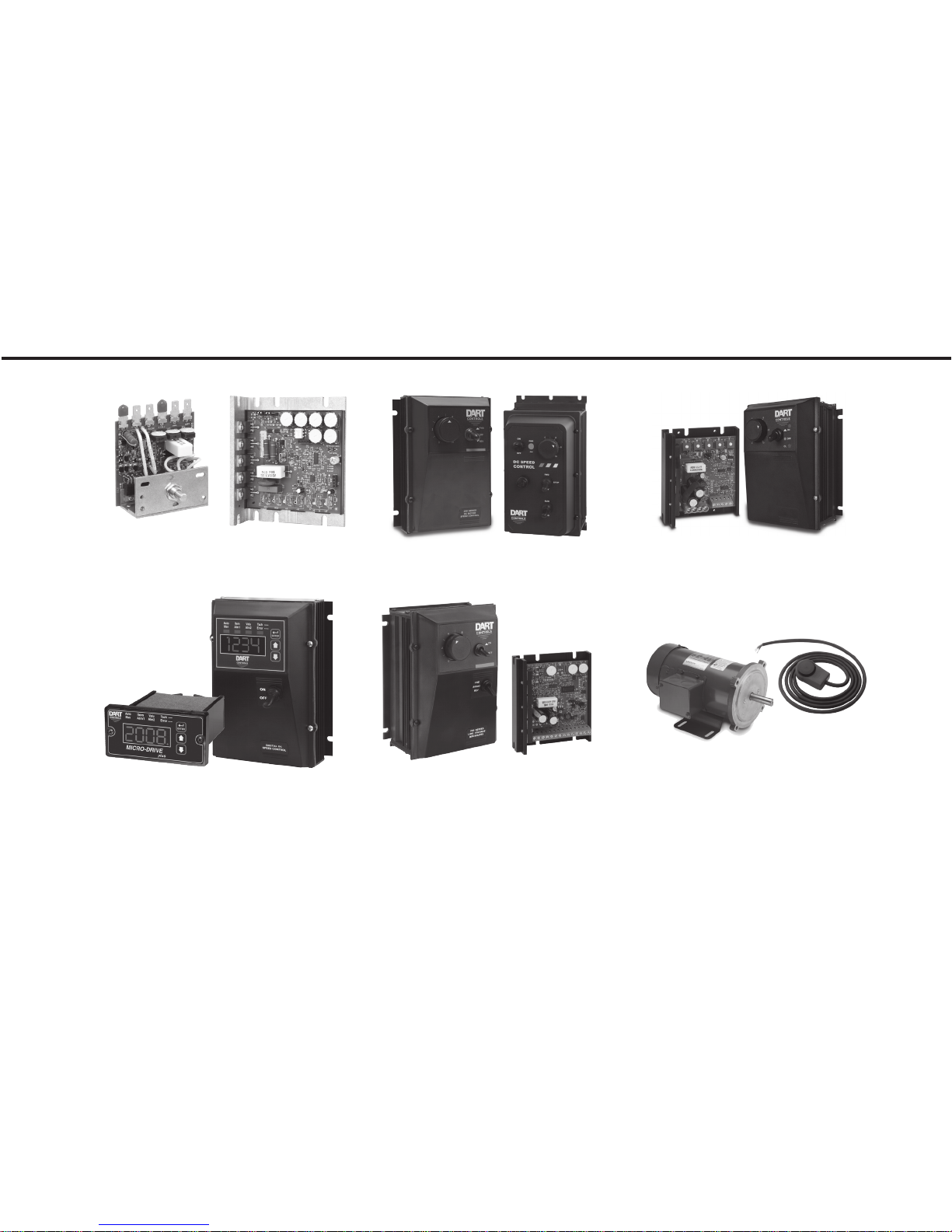
YOUR MOTOR SPEED CONTROL SOLUTION PROVIDER
OEM Chassis SCR Drives
Dual Input voltage, adjustable HP
range, isolated signal follower and
Closed loop accuracy, 4-20mA and
Dart Controls, Inc. is a
designer, manufacturer, and
marketer of analog and
digital electronic variable
speed drives, controls, and
accessories for AC, DC,
and DC brushless motor
applications.
reversing options
Digital SCR Drives
serial communications, integral
programmable display
Shown above is just a
sampling of the expanded
line of Dart controls that
feature the latest in electronic
technology and engineering.
Products are manufactured
in the U.S.A. at our Zionsville
(Indianapolis, Indiana)
NEMA 4/4X SCR Drives
Dual Input voltage, adjustable HP
range, isolated signal follower and
reversing options
Brushless DC Drives
Closed loop accuracy, line and low
voltage versions through 1 HP
production and headquarters
facility - with over 2,000,000
variable speed units in the
field.
In addition to the standard
off-the-shelf products, you
can select from a wide variety
of options to customize
controls for your specific
application. For further
information and application
assistance, contact your local
Dart sales representative,
stocking distributor, or Dart
Controls, Inc.
Low Voltage/Battery
PWM Drives
Chassis and NEMA 4X versions,
speed pot and signal follower
operation
Digital Accessory &
Resale Items
Motors to 700 HP, VFD's to 200
HP, NEMA rated encoder, digital
programmable potentiometers and
tachometers
Dart Controls, Inc.
Manufacturer of high quality
DC and AC motor speed
controls and accessories
since 1963.
P.O. Box 10
5000 W. 106th Street
Zionsville, Indiana 46077
Phone: (317) 873-5211
Fax: (317) 873-1105
www.dartcontrols.com
ISO9001 REGISTERED
MADE IN USA
 Loading...