


B
-
DVR
MPEG
-2
DIGITAL VIDEO RECORDER
User
’
s Guide
Rev. 2.0.0
Darim Vision Co., Ltd.

B-DVR User
’
s Guide
ii

B-DVR User
’
s Guide
iii
Notice
The information in this document is subject to change without prior notice in order to improve reliability,
design, or function and does not
represent a commitment on the part of this company.
In no event will we be liable for direct, indirect, special, incidental, or consequential damages arising out
of the use or the inability to use the product or documentation, even if advised of the po
ssibility of such
damages.
Copyright
© 2001 Darim Vision Co., Ltd.
All Rights Reserved.
No part of this reference manual may be reproduced or transmitted in any form or by any means without
the prior written permission of this company.
Throughout this m
anual, we make reference to product names that are trademarks of other companies.
We are using these names for identification purposes only, with no intention of infringement of the
trademarks.
FCC
Information
This equipment has been tested and found to
comply with the limits for a Class B digital device, pursuant
to Part 15of the FCC Rules. These limits are designed to provide reasonable protection against harmful
interference in a residential installation. This equipment generates, uses and can radia
te radio frequency
energy an, if no installed and used in accordance with the instructions, may cause harmful interference to
radio communications. However, there is no guarantee that interference will not occur in a particular
installation. If this equip
ment does cause harmful interference to radio or television reception, which can
be determined by turning the equipment off and on, the user is encouraged to try to correct the interference
by one of more of the
following
measures:
l
Reorient or relocate th
e receiving antenna.
l
Increase the separation between the equipment and receiver.
l
Connect the equipment into an outlet on a circuit different from that to which the receiver is
connected.
l
Consult the dealer or an experienced radio/TV technician for help.

NOTICE
B-DVR User
’
s Guide
iv
S
hielded cables and I/O must be used for this equipment to comply with the relevant FCC regulations.
Changes or modifications not expressly approved in writing by Darim Vision Co. Ltd. May void the user
’
s
authority to operate this equipment.
Limited Warra
nty
Our company warrants this product against defects in materials and workmanship for a period of one year
from the date of purchase. During the warranty period, products determined by us to be defective in form
or function will be repaired or replaced
at our option. This warranty does not apply if the product has
been damaged by accident, abuse misuse, or as a result of service or modification other than by us.
This warranty is in lieu of any other warranty expressed or implied. In no event shall we
be held liable
for incidental or consequential damages, such as lost revenue or lost business opportunities arising from
the purchase of this product.

B-DVR User
’
s Guide
v
CONTENTS
1 INTSRUCTION
________________________________
_________________________
1
2 SPECIFICATION
________________________________
_______________________
3
3 FRONT PANEL AND REAR PANEL
________________________________
_______
5
4 PREPARATION AND INSTALLATION
________________________________
_____
7
4.1 What is in Package
________________________________
_________________
7
4.2 Installation
________________________________
_______________________
10
5 B-DVR FUNCTION
________________________________
____________________
17
5.1 Front Panel Button
________________________________
________________
17
5.2 VFD Display
________________________________
_____________________
19
5.3 Basic Function
________________________________
____________________
20
5.4 JOG-SHUTTLE Function
________________________________
__________
26
5.5 MARK Button
________________________________
____________________
29
5.6 BOOKMARK Button
________________________________
______________
32
5.7 JUMP Function
________________________________
___________________
33
6 B-DVR MENU
________________________________
_________________________
35
6.1 Main Menu
________________________________
______________________
35
6.2 DVR Setup
________________________________
_______________________
37
6.3 Screen Setup
________________________________
_____________________
39
6.4 Video Setup
________________________________
______________________
41
6.5 Schedule Setup
________________________________
___________________
43

CONTENTS
B-DVR User
’
s Guide
vi
6.6 System Info
________________________________
______________________
46
6.7 Play-List ________________________________
_________________________
49
6.8 ALL CLIPS
________________________________
______________________
51
6.9 Playing the Play
-
List ________________________________
_______________
52
6.10 Playing the ALLPLAYLISTS
________________________________
_______
54
6.11 Editing Play
-
List ________________________________
__________________
55
6.12 Changing names of the Play
-
List ________________________________
_____
58
6.13 Deleting the Clip from the Play
-
List ________________________________
__ 60
6.14 Managing Clip
-
List ________________________________
________________
62
6.15 Play Clip
-
List Items
________________________________
_______________
63
6.16 Change the names
of the Clip
-
List items
______________________________
64
6.17 Delete Clip
-
List Items
________________________________
______________
66
7 B-DVR DESKTOP SOFTWARE
________________________________
__________
69
7.1 B-DVR Desktop Software
________________________________
___________
70
7.2 Clip-List Menu
________________________________
___________________
71
7.3 Play-List Menu
________________________________
___________________
73
7.4 B-DVR Hard Disk Optimization
________________________________
_____
74
7.5 Settings
________________________________
__________________________
75
8 HARD DISK MANAGEMENT AND HOW TO USE
__________________________
79
8.1 B-DVR Hard Disk Jumper Setting
________________________________
___ 79

CONTENTS
B-DVR User
’
s Guide
vii
8.2 How to use B
-
DVR HDD on general PC
_______________________________
79
9 TROUBLE
SHOOTING
________________________________
__________________
81
9.1 How to solve the trouble of B
-
DVR
________________________________
___ 81
9.2 Messages occurred B
-
DVR activation
________________________________
_ 83
9.3 Upgrade Information and Technical Support
__________________________
86

CONTENTS
B-DVR User
’
s Guide
viii

B-DVR User
’
s Guide
1
1 INTSRUCTION
DVR is short term of Digital Video Recorder.
It is a device
which digitizes input video/audio
signal and store in digital data.
It replaces the existing VTR which stores analog AV recorder
via tape(VHS) as well as gives users useful advantage in digital data.
The B-
DVR from Darim Vision is a state
-of-
art DVR not only having general function of DVR
but also automated scheduling playb
ack function.
The B-
DVR is designed for everyone to use easily like general VTR.
There are many DVRs
which use CD
-
R, CD
-
RW in the market.
B-DVR uses
remov
able Hard Disk and gives the
users get storage space easily and economically.
Digital data that
has no
quality
loss is the most suitable to save the data and to reuse if
comparing with analog data.
With using this feature, you can convert AV data into real
time
high quality MPEG
-
2 and save it to the Hard Disk.
And it gives you related function by
connecting stored hard disk to a PC using high storage of high quality MPEG
-2. Now with
B-DVR from Darim, you will get variable function which only high quality digitized AV data
can has like a
n existing VTR.
The unique function of
B-DVR is automated s
cheduling function for recording and playback.
It is a function that playbacks the stored AV data on demand time.
The several video
clips
with this function can be edited as the one Play
-
List so that users can reuse the several video
clips or repeated
video clips by simple editing effectively and appropriately.
B-DVR can be used as general, home
-
user AV device, but it has high capacity of storage
H
ard
disk and provides high quality MPEG
-
2 video data for next generation multi
-
use AV device.
Therefore
it also would be the most suitable device for professional users and industry
which
demand highly developed multi
-
media technology.

INSTRUCTION
B-DVR User
’
s Guide
2

B-DVR User
’
s Guide
3
2 SPECIFICATION
Feature
Spec Remark
Storage
Removable Hard disk
(IDE)
Storage capacity
20GB/40GB
/60GB/80GB/120GB/
250GB
Compression
MPEG
-
2 Video, MPEG 1 Layer II Audio
Video Format
CCIR601 NTSC/PAL
Video Input
Composite
S-
Video
Video Output
Composite
S-
Video
YUV
Component
RGB
Audio Input
Stereo
RCA (47㏀
Unbalanced)
Audi
o Output
Stereo
RCA (600Ω Unbalanced)
Recording Format
NTSC 704x480 at 30FPS
PAL 704x576 at 25FPS
Compression
(Constant Bit
-
rate)
Normal
Compression rate
: 4.5
Mbps
Super
Compression rate : 6.0Mbps
Maximum recording
time
40hours
(
30fps, 4.5Mbps, Normal Audio)
With
80GB
Hard disk
30hours (30fps, 6.0Mbps,
Normal Audio)
Scheduled recording
Off
/Playback/Record
(Max.10 Schedules)
Play List
Max 300 Video Clips
Title Edit
List Edit
Making a clip by Mark In/Out
Playback Mode
Repeat, Once
Front Panel
Time Code
/List Information Display
Shuttle
2x,4x,8x,16x
Slow Motion
1/2x,1/4x,1/8x
Jog
Yes
Front Display Device
VFD
OSD Menu
Yes
Serial Interface
RS232/RS422 (SONY Protocol)

SPECIFICATION
B-DVR User
’
s Guide
4
Power
115/230 V AC, 50/60Hz
Power Consumption
Approx.
50W
Size (WxHxD)
420x88x380
Weight
Approx.
7Kg
[Table
2.1] Specification

B-DVR User
’
s Guide
5
3 FRONT PANEL AND REAR PANEL
[Picture
3.1
] Front Panel and Names
1
POWER
button
11
PLAY
button
2 Shuttle ring
12
STOP
button
3 Jog 13
PASUE/STILL
button
4 VFD window
14
DISPLAY
button
5
▶
(Right
-
hand direction) button
15
RECORD
button
6
LIST button
16
MARK
OUT but
ton
7
▲
(Upward) button
17
▼
(Downward) button
8
MENU
button
18
SELECT
button
9
◀
(Left-hand direction) button
19
MARK
IN
button
10
1 ~ 5
button
20
BOOKMARK
button
8 7 5 10 9 6 4 3
11 12 13 14 15 16 17
18
19 20
1 2

FRONT PANEL AND REAR PANEL
B-DVR User
’
s Guide
6
[Picture
3.2
] Rear Panel and Name
s
1 S-Video input
9
Cooling Fan
2 S-Video output
10
Composite Video input
3 Composite Video output
11
Audio Left input
4 Audio Left output
12
Audio Right input
5 Audio Right output
13
Power cord
6 B/R-Y output
7 G/B-Y output
8 R/Y output
9 2
13 12 11
1 3 4
10
8 5 7 6

B-DVR User
’
s Guide
7
4 PREPARATION AND INSTALLATION
4.1 What is in Package
[Picture
4.1] B-DVR Power cord 1 unit
[Picture
4.2] Composite cable 2 units
[Picture
4.3] S-Video cable 2 units

PREPARATION AND INSTALLATION
B-DVR User
’
s Guide
8
[Picture
4.4] 80GB Hard Disk (installed in the B
-
DVR originally but opti
on
al in some
cases)
[Picture
4.5
] Hard Disk Rack 1 unit(installed in the B
-
DVR)
[Picture
4.6
] B-DVR Desktop(Hard Disk Utility) Software for PC

PREPARATION AND INSTALL
ATION
B-DVR User
’
s Guide
9
[Picture
4.7
] User
’
s Guide
[Picture
4.8
] Limited Warranty

PREPARATION AND INSTALLATION
B-DVR User
’
s Guide
10
4.2 Installation
4.2.1
Plu
g in the power cord
Make sure to read the installation instruction in detail before plug in the power cord.
Before
connecting
B-DVR to other device, plug in the power cord according to the instruction in this
chapter.
The power cord protects
B-DVR from the electrical dama
ge by ground.
Follow
the instruction.
Installation
1.
Make sure the mentioned usable voltage limit of the
B-DVR back panel suits the type of
voltage system to be connected.
The voltages (220V/50Hz, 220V/60Hz) are suitable for
B-DVR. Confirm again t
he voltage type to be connected before connecting.
Installation
2.
Connect the end of
B-DVR power cord to the socket of the
B-DVR back panel.
Installation
3.
Plug in the other end of power cord into the grounded 3
-
hole receptacle or the multi
-
hole
outlet.
Note
)
B-
DVR is ground safe and has 3
-
line grounded plug.
Consult to the engineer if you can't
plug the power cord grounded AC receptacle.
[Picture
4.9]
Connected power cord to
B-DVR

PREPARATION AND INSTALL
ATION
B-DVR User
’
s Guide
11
4.2.2
Connection
AV device to B
-
DVR
You can connect various kinds of AV devices including general AV I
/
O devices mentioned
in the chapter.
Please refer the manufacture's guide if you are going to connect ot
her
devices.
The B-
DVR can be connected with various I
/
O devices or its own use. Refer to the following
table according to the type of input or output.
There are Composite Cable, S
-
Video Cable
and RGB Cable in the B
-
DVR.
Video input
Video output
Aud
io input
Audio output
Composite
cable O O O O
S-Video
cable O O X X
RGB
cable X O X X
[Table
4.1
] Supported input/output cable in B
-
DVR

PREPARATION AND INSTALLATION
B-DVR User
’
s Guide
12
Follow the instruction to connect each cable at the following.
Sample.1)
Connect S
-
Video into input connector and use the monitor to play from
B-DVR
Composite, S
-
Video and RGB.
[Picture
4.10
] In the situation for S
-
Video input and S
-
Video output

PREPARATION AND INSTALL
ATION
B-DVR User
’
s Guide
13
[Picture
4.11
] For S
-
Video input and Composite output
[Picture
4.12
] For S
-
Video input and RGB output

PREPARATION AND INSTALLATION
B-DVR User
’
s Guide
14
Sample.2)
Connect Composite to input connector port and use monitor to play from
B-DVR
Composite, S
-
Video and RGB.
[Picture
4.13
] For Composite input and S
-
Video output

PREPARATION AND INSTALL
ATION
B-DVR User
’
s Guide
15
[Picture
4.14
] For Composite input and Composite output
[Picture
4.15
] For Composite input and RGB output

PREPARATION AND INSTALLATION
B-DVR User
’
s Guide
16

B-DVR User
’
s Guide
17
5 B-DVR FUNCTION
5.1 Front Panel Button
[Picture
5.1
] B-DVR Front Panel Button
1
POWER
button
11
PLAY
button
P
ress to switch on/off B
-
DVR
.
S
tart to play
2 Shuttle ring
12
STOP
button
S
huttle clockwise direction(FF) or
counterclockwise direction(FB) and A
V
data is 2x/4
x
/8x/16x.
S
top playback/recording
.
3 Jog 13
PAUSE/STILL
button
S
earching by one frame forward or
backward after pause
.
P
ause playing
.
4 VFD window
14
DISPLAY
button
D
isplay B
-
DVR information.
D
isplay time or List in the VFD
window.
5
▶
(Right
-
hand direction) button
15
RECORD
button
M
oves in the Menu setup and from the list
to the item or to the clip.
Search forward by
5% in pause mode.
R
ecord the video source input.
6
LIST
button
16
MARK
OUT
button
P
ush to convert to the Play
-
List menu
F
inish to edit the necessary
video
s
ource
in play mode.
8
7
5
10 9
6
4
3
11 12 13 14 15
16 17
18
19
20
1
2

B-DVR FUNCTION
B-DVR User
’
s Guide
18
7
▲
(Upward) button
17
▼
(Downward) button
C
hange the setup value of item.
C
hange the setup value of item.
8
MENU
button
18
SELECT
button
C
onvert to the Main menu.
S
elect the item.
9
◀
(Left-hand direction) button
19
MARK
IN
button
M
oves to the
item in the Menu
setup and
List.
Moves back to the clip in playback in
the Play-list.
Search backward by 5% in
pause mode.
S
tart to edit the necessary video
s
ource in
play mode.
10
1 ~ 5
button
20
BOOKMARK
button
P
ush 1-
5 for bookmark.
B
ookmark to make it easy to
select
in clip play
mode.

B-DVR FUNCTION
B-DVR User
’
s Guide
19
5.2 VFD Display
[Picture
5.2
] VFD window display
1) (ALARM) display
Indicates the schedule setup for playing
or recording
on the defined date and time.
2) REC display
Indicates the video source is being recorded.
3) FB, PAUSE, PLAY, FF display
Indicates B
-
DVR i
s occupied in Fast backward, Pause, Play and Fast
forward.
4) Counter display
Indicates the system time display, list information, recording
time and playback time.

B-DVR FUNCTION
B-DVR User
’
s Guide
20
5.3 Basic Function
5.3.1
DISPLAY Button
[Picture
5.3] DISPLAY
button
DISPLAY
button enables users to select the contents of VFD window either
“Time display”
or
“List Information display”
.
When you press
DISPLAY
button once, the
“Time display”
is shown.
If you press
DISPLAY
button again, the
“List Inf
ormation display”
is shown.
Two display contents are shown in terns when you press the button continuously.
Note that
DISPLAY
button is only activated in the
STOP
mode.
It doesn't work in other
modes.
5.3.1.1
Time Display
The
RTC(Real Time Clock)
is installed
in the B
-
DVR which is used in the whole system and
user can setup the time and date in the DVR setup from the
M
ain Menu.
The setup time and
date run when the power is off and it is used when necessary like schedule function.
You can
use this function w
hen you want to display the setup time.
[Picture
5.4
] Example of time display
[Picture
5.4] shows the present setup time in the B
-
DVR.
It is
“03-
12 12:05
:25”
and means

B-DVR FUNCTION
B-DVR User
’
s Guide
21
12:05:25, March 12.
5.3.1.2
OSD Display
OSD information is shown at the upper right on the screen d
uring Record and Play. At
6.3
Screen Setup
, OnLineInfo(None/Simple/Detail) can be set and the OSD shown on the screen
during Record
or
Play can be set as OnLineInfo(None/Det
ail) by pressing
DISPLAY
button.
5.3.2
PLAY Button
[Picture
5.5] PLAY
button
With
B-DVR
, you can play the saved MPEG
-
2 file from the installed Hard Disk in real
time to
a monitor by connecting to the output port.
When you start
B-DVR after switching on Power
button, it remembers the information
of the item lately used after searching it from the installed
Hard Disk.
When you command to select an item from the Play
-
List or Clip
-
List, B-
DVR
has the function to re
member
the selected content in the Hard Disk.
Once
B-DVR activates,
the one item l
ist is always ready.
[Picture
5.6
] VFD display in playback mode
Press the
PLAY
button when you want to play.
As soon as pressing the
PLAY
button, the
VFD window shows as
[Picture
5.6].
The shown “
12:05:25
” indicates the Time
-
Code value

B-DVR FUNCTION
B-DVR User
’
s Guide
22
r
elated to playback.
It means to proceed for “
12 hour 05
minutes 25
seconds
” from
the starting point of video source.
“▶” indicates playback.
Once you press
PLAY
button,
it displays the saved MPEG
-
2 file to a monitor or to other AV device through vide
o output port.
Press
STOP
button shown in
[Picture
5.7]
to stop playback command.
5.3.2.1
SLOW Playback
During play, press
▲
button in case that the customer wants slow playback. With the
pressing of
▲
button once, twice, and three tim
es, playback goes to 1/2x, 1/4x, 1/8x. To stop
the execution of slow playback, press
PAUSE
button. as shown at
[Picture
5.10].
5.3.3
STOP Button
[Picture
5.7] STOP
button
You can stop the c
ommand processing by pressing
STOP
button in record, playback and pause
modes.
When pressing
STOP
button, the Time
-
Code information related to the recording,
playback and pause command disappears in the VFD window and the selected Display from
either “
Ti
me Display
” or “
List Information Display
” appears in the VFD window.
Pressing
STOP
button to stop all the command processing,
MENU
button and
LIST button are
ready to activate. Therefore, to setup Main Menu and to command or to edit List Information
are
only possible in the stop mode.

B-DVR FUNCTION
B-DVR User
’
s Guide
23
5.3.4
RECORD Button
[Picture
5.8] RECORD
button
The B-
DVR can record the video connected from the input port in real
time in MPEG
-
2 file to
the installed Hard Disk.
After switch
ing on the power,
B-DVR is ready to activate by
initializing the installed Hard Disk or preparing to record.
With this function, you can record
video source instantly in real
time.
Therefore, once
B-DVR activates, it is always ready to
record and save.
[Picture
5.9
] VFD display in record mode
Press
RECORD
button to record the video source presently input to the
B-DVR. It is shown
in VFD window as
[Picture
5.9]
simultaneously by pressing
RECORD
button.
The
“
12:05:25
” displays the Time
-
Code value related to the recording.
It means the time to be
recorded for “
12 hour 05 minutes 25
seconds
” from the beginning points.
"
REC
▶
"
displays recording.
When you press
RECORD
button, it records and saves the
input video source from the input
port in real
time in MPEG
-
2 file to the installed Hard Disk.
It registers the saves file in the
Clip-List.
The latest recording file is registered in No.
0
0 which is highest order of Clip
-
List.
If you want to play ot
her clip, you can play it in the Clip
-
List referring playback.
Press
STOP
button to stop record command processing.

B-DVR FUNCTION
B-DVR User
’
s Guide
24
5.3.5
PAUSE Button
[Picture
5.10] PAUSE
button
5.3.5.1
PLAY Pause
You can pause play command processing pressing
PAUSE
button in play mode.
In pause
mode, you can use search function using Jog and S
huttle
.
The Time
-
Code value of the
allocated position of video source i
n pause mode shows in the VFD
window
and it enables users
to search the file exactly.
[Picture
5.11
] VFD display in play pause mode
Press
PAUSE
button when you want to pause in play mode.
The display shown
in
[Picture
5.11]
appears when pressing
PAUSE
button.
The “
12:05:25
” indicates the Time
-
Code value
related to pause.
It means to pause for processing for “
12 hour 05 minutes 25 seconds
”
from the beginning point
.
“
█ █
” indicates pause.
Press
STOP
button or
PLAY
button to stop pause command processing.
5.3.5.2
RECORD Pause
You can pause record command processing pressing
PAUSE
button in record mode.

B-DVR FUNCTION
B-DVR User
’
s Guide
25
[Picture
5.12
] VFD display in
record pause mode
Press
PAUSE
button when you want to pause in record mode.
The display shown in
[Picture
5.12]
appears when pressing
PAUSE
button.
The “
12:05:25
” indicates the Time
-
Code value
related to pause.
It means to pau
se for processing for “
12 hour 05 minutes 25 seconds
”
from the beginning point.
“
█ █
” indicates pause.
Press
STOP
button or
RECORD
button to stop pause command processing.

B-DVR FUNCTION
B-DVR User
’
s Guide
26
5.4 JOG
-
SHUTTLE Function
[Picture
5.13
] Jog-Shuttle
The B-
DVR has Jog
-Shuttle
function in order to search conveniently.
The function of Jog
activates in pause mode, pressing
PAUSE
button during the play mode.
The function of
Shuttle activates either in play mode or in pause mode.
Jog is used for searching still image
,
Shuttle
is used for fast searching like at 2x, 4x,
8x
, 16x
speed.
5.4.1
JOG
Function
JOG function activates in pause mode while the video source is playing.
You can search by
one frame either forward or backward in the position of pause.
When you turn the Jog in
clockwise direction from the front side, the
still image being played by one frame in the
direction of normal playback.
When you turn the Jog in counter clockwise direction from the
front side, the still image is being played by one frame backward.
5.4.2
SHUTTLE Function
SHUTTLE starts in the
play or
pause
mode.
By turning the Shuttle clockwise or
counterclockwise, slowly or fast.
The wanted video clip can be searched.
While S
huttle
for Fast Forward or Fast Rewind being used, Screen and VFD
window
show
different signals as follow
ing pictures
:
Jog
Shuttle

B-DVR FUNCTION
B-DVR User
’
s Guide
27
[
Picture
5.14
] Fast Forward on screen
[Picture
5.15
] Fast Forward on VFD
[Picture
5.16
] Fast Rewind on screen

B-DVR FUNCTION
B-DVR User
’
s Guide
28
[Pictu
re 5.17] Fast Rewind on VFD

B-DVR FUNCTION
B-DVR User
’
s Guide
29
5.5 MARK Button
[Picture
5.18] MARK
IN,
MARK
OUT
button
“
Marking
” can select the wanted video by marking the starting and ending part a
nd then make
new video clip.
Using “
Marking
”, it is easy to make required clip from already recorded
video clip without using an editing tool or re
-
recording video.
As shown at
[Picture
5.18],
there are two buttons;
MARK
IN for indicating the starting part and
MARK
OUT for the
ending part.
5.5.1
Using Marking Function
①
Refer to
“
6.15.1
Play Clip
-
List Items
” and se
lect a video clip to apply to the Marking
function
.
②
M
ake sure that the select
ed video clip is
viewed as pause on the screen.
③
Press the
PLAY
button and play till new clip is to start or use the Jog
&
Shuttle
to the
starting part for new clip and then press
PAUSE
button.
④
Press
MARK
IN
button in the state of pause.

B-DVR FUNCTION
B-DVR User
’
s Guide
30
[Picture
5.19
] MARK IN
⑤
OSD appears as shown at the
[Picture
5.19]
in the normal operation and performs
Mark In
.
⑥
Press
PLAY
button
again until the ending part of the video for the new clip or use Jog
&
S
huttle
and then pr
ess
PAUSE
button
.
⑦
Press
MARK
OUT button
in the state of pause.
[Picture
5.20
] MARK OUT
⑧
OSD appears as shown at the
[Picture
5.20] in the normal operation and performs M
ark
Out
.
⑨
After Mark In and M
ark Out
are done, new clip named MARK## is added on the Clip
-
List.

B-DVR FUNCTION
B-DVR User
’
s Guide
31
[Picture
5.21
] New Clip

B-DVR FUNCTION
B-DVR User
’
s Guide
32
5.6 BOOKMARK Button
[Picture
5.22] BOOKMARK
button
BOOKMA
RK is the function that reminds the information on whereabouts of clips in the work
of Play
-
List or Clip
-
List and that helps the clips to directly move the specific clip. The
maximum five units of
specif
ic
clips
can be saved
on the BOOKMARK.
With the p
ressing
of number
1 ~ 5 , all the clips move to the specific clip saved previously and standby.
5.6.1
Using Bookmark Function
①
Refer to
“
6.15.1
Play Clip
-
List Items
” and s
elect a video clip to apply to the B
ookmark
function
.
②
Make sure that the selected video clip is
viewed as pause on the screen.
③
Press the
PLAY
button and play till
the video clip to be saved to the Bookmark function
or
use the J
og & Shuttle
and then press
PAUSE
button
.
④
Press
BOOKMARK
button in the s
tate of pause.
⑤
After pressing
BOOKMARK
button, press
number among
1 ~ 5 .
⑥
In the state of stop or pause from the selected number
1 ~ 5
, video clips can
always be moved to the saved specific clip.

B-DVR FUNCTION
B-DVR User
’
s Guide
33
5.7 JUMP Function
In case that the size of the recor
ded clip is large, it takes to long time to move to the certain
position with Jog & Shuttle. JUMP function helps to move to the wanted position with ease.
It searches very fast regardless of the size of the clip. There is a function of skimming
throu
gh using JUMP function. Out of 100% Clip you can skip 5% or 1% either forward or
backward you can control the JUMP function from 0%
―
95% that you can easily search the
video.
5.7.1
Using JUMP Function
①
Refer to
“
6.15 Play Clip
-
List Items
” and
select a video clip to apply to the
JUMP
function
.
②
Make sure that the selected video clip is
viewed as pau
se on the screen.
③
Using
◀
button and
▶
button, search goes forward or backward by 5% and with
▲
button and
▼
button, it goes
forward
or backward by 1%.
[Picture
5.23
] 50% JUMP example [Pict
ure 5.24] 75% JUMP example

B-DVR FUNCTION
B-DVR User
’
s Guide
34

B-DVR User
’
s Guide
35
6 B-DVR MENU
6.1 Main Menu
Main Menu appears after pressing the
MENU
button as shown the below picture. Refer to
[Picture
6.2
]
[Picture
6.1] MENU
button
There are four items on the Main Menu.
·
DVR Setup
: Play mode, Beep, Date and Time can be set.
·
Screen Setup
: OSD related can be set.
·
Video Setup
: Input and output, and video compression rate can be set.
·
Sche
dule Setup
: Schedules to play or record can be set.
·
System Info
: Displays settings and system version information.
Also Main Menu shows the current
B-DVR version. The
[Picture
6.2
] shows version 2.0.

B-DVR MENU
B-DVR User
’
s Guide
36
[Picture
6.2
] Main Menu Screen
6.1.1
General Setting
①
The above screen appears on pressing
MENU
button.
②
Using
▲
, ▼
button to move to each item, and select the item and press the
SELECT
button.
[Picture
6.3] SELECT
button
③
To move item, use
▲
, ▼
button.
④
To change the value, use
◀
, ▶
button.
⑤
To end the Main Menu, press the
MENU
button again.

B-DVR MENU
B-DVR User
’
s Guide
37
6.2 DVR Setup
Language, Date and Time, Play Mode and Buzzer can be set in DVR Setup.
[Picture
6.4
] DVR Setup
There are five items set in DVR Setup.
·
Language
: Language, used for the entire system, can be set.
·
Date
: Date can be set.
·
Time
: Time can be set.
·
Play Mode
: Play times(Once or Repeat) can be set.
·
Buzzer
: On or Off can be set.
6.2.1
General
Setting
①
Main Menu appears on pressing
MENU
button.
②
Using
▲
, ▼
button, move to the
“
DVR Setup
”.
③
On pressing
SELECT
button, DVR Setup is done as shown on
[Picture
6.4
].
④
To change
the item, use
▲
, ▼
button, to move to
“
Language
”, “
Date
”, “
Time
” ,
“
Play Mode
”, “
Buzzer
”
.
⑤
To change the value, use
◀
, ▶
button.

B-DVR MENU
B-DVR User
’
s Guide
38
The following shows the value of each item.
Menu
Category
Value
DVR Setup
Language
English, Korean
Year 2002 ~ 2099
Mo
nth 01 ~ 12
Day 01 ~ 31(30/29/28)
Hour 00 ~ 23
Min 00 ~ 59
Sec 00 ~ 59
Play Mode
Repeat : Repeats playing
a
clip.
1(Pause) :
P
lays once then pauses at the end of clip.
1(Stop) :
P
lays once then goes back to live mode.
Buzzer
On, Off
⑥
After se
tting all values, press the
MENU
button to return to Main Menu.
⑦
To end the Main Menu, press the
MENU
button again.

B-DVR MENU
B-DVR User
’
s Guide
39
6.3 Screen Setup
Screen Setup sets the OSD modes.
[Picture
6.5
] Screen Setup
Screen Setup has following items:
·
Online Info : can set OSD(On Screen Display).
6.3.1
General Setting
①
Main Menu appears on pressing
MENU
button.
②
Using
▲ ,
▼
button, move to the
“
Screen Setup
”.
③
On pressing
SELECT
button,
“
Sc
reen Setu
p
” is done as shown on
[Picture
6.5].
④
Using
◀
, ▶
button, value can be set.
The following shows the value of each item.
Value
Contents
Detail
1. Command appears on the upper left.
2. OSD shows the information on Comman
d on the
upper right.

B-DVR MENU
B-DVR User
’
s Guide
40
- Play: play time, the name and number of Clip or
Play list
- Record: the remaining capacity of HDD and clip,
and also the recording time and bit rate
3. The contents of error are listed on the upper side of
the screen.
Simple
1. Com
mand appears on the upper left.
2. The contents of error are listed on the upper side of
the screen.
None
1. Only the contents of error are listed on the upper
side of the screen.
⑤
After setting all values, press the
MENU
button to return to Main Menu.
⑥
T
o finish the Main Menu, press the
MENU
button again.

B-DVR MENU
B-DVR User
’
s Guide
41
6.4 Video Setup
Video Setup is a port where the input and output are determined. The resolution of video
recording is also selected. B
-
DVR accepts both PAL(25fps) and NTSC(30fps). When the
NTSC TV
set is used, be sure to connect an NTSC video source to the input port because
default output is set to the PAL when turning on power without video input signal. B
-
DVR
default Video Setup input is Composite and out put is S
-
Video (Composite), respectivel
y.
Such setup is also applied when a new Hard Disk is connected.
Quality represents the degree of compression when digitizing input video the Hard Disk in
MPEG
-
2 format.
The quality is determined by amount of data in MPEG
-
2 stream per second
measured i
n Mbps. Higher numbers represent better quality but consume more Hard Disk
space.
In B-DVR the quality
level can chosen between 4.5Mbps(Normal) and 6.0Mbps(Super).
[Picture
6.6
] Video Setup
There are three items in Video Setup.
·
Input : can set the video input port.
·
Output
: can set the video output port.
·
Quality
: can set the bit
-
rate of video.

B-DVR MENU
B-DVR User
’
s Guide
42
6.4.1
General Setting
①
Main Menu appears on pressing
MENU
button.
②
Us
ing ▲
, ▼
button, move to the
“
Video Setup
”.
③
On pressing SELECT,
“
Video Setu
p
” is done as shown on
[Picture
6.6].
④
Using
▲
, ▼
button, move to
“
Input
”, “
Output
”, “
Quality
”.
⑤
To change the value, use
◀
, ▶
button.
Th
e following shows the value of each item.
Item Value
Contents
Input
Composite
S-Video
Output
S-Video(Composite)
RGB
Component
YUV
Quality
Normal
Bit-Rate : 4.5Mbps
Super
Bit-Rate : 6.0Mbps
⑥
After setting all values, press the
MENU
button t
o return to Main Menu.
⑦
To finish the Main Menu, press the
MENU
button again.

B-DVR MENU
B-DVR User
’
s Guide
43
6.5 Schedule Setup
Enables to set up 10 schedules of starting and ending hours.
The following steps explain how
to set up for the schedule.
[Picture
6.7
] Schedule Setup
6.5.1
General Setting
①
Press
MENU
button to display Main Menu
.
②
To go to “
Schedule Setup
”, use
▲
, ▼
buttons.
③
Press
SELECT
button, then move to “
Schedule Setup
” screen. It displays
as shown in
[Picture
6.
7].
④
Use ▲
, ▼
buttons to move to the category the user needs to change the value.

B-DVR MENU
B-DVR User
’
s Guide
44
[Picture
6.8
] Schedule Setup
⑤
On “Schedule Edit” screen showing above, “Current Time” displays the current hour that
is alrea
dy setup. “Number” shows the order of schedule. To move to other schedules,
use ◀
, ▶
buttons after selecting the menu “Number”.
⑥
“
Start Time
” shows the starting hour of recording and playing. To setup the hour of
“
Start Time
”, select the menu “
Hour
” and
“
Min
”, then use
◀
, ▶
buttons to change
the value.
⑦
“
End Time
” shows the
ending
hour of recording and playing. To setup the hour of “
End
Time
”, select the menu “
Hour
” and “
Min
”, then use
◀
, ▶
buttons to change the
value
⑧
The menu “
Mode
” designates either
sc
hedule
recording or playback the clips which can
be selected by the user.
⑨
In case the value “
Record
” is selected, the user enables to select the “
Bitrate
(
Normal
/
Super
)” by using
◀
, ▶
buttons
.
⑩
In case the value “
Play
” is selected, the user enables to sele
ct “
Play List
(
All Clips
/
All
PlayLists
/
PlayList
)” by using
◀
, ▶
buttons.
⑪
The menu “
Previous
” shows the starting, ending time and mode of the previous schedule
.
⑫
The menu “
Next
” shows the starting, ending time and mode of the next schedule.
⑬
When the startin
g and ending time for schedule are set as “00:00”, the system does not
operate either “Recording” or “Playback”.
⑭
Press
MENU
button to return to the Main Menu
.
⑮
Press
MENU
button again to finish the Main Menu.
If record/play schedule is setup

B-DVR MENU
B-DVR User
’
s Guide
45
on the specif
ied time, then the alarm “
” in red will be displayed on VFD window as
shown in
[Picture
6.9].
[Picture
6.9] Example of Schedule Setup

B-DVR MENU
B-DVR User
’
s Guide
46
6.6 System Info
On “System Info” screen, it shows the general information of system including hard disk quota.
The menu “Factory Setting” is to set up to default setting.
[Picture
6.10
] System Info
6.6.1
General Setting
①
Press
MENU
button to display Main Menu
.
②
To go to “
System Info
” screen, use
▲
, ▼
buttons.
③
Press
SELECT
button, then move to “
System Info
” screen. It displays
as shown
[Picture
6.10].
④
Explanation pertaining to each category is as shown on the following chart.

B-DVR MENU
B-DVR User
’
s Guide
47
Menu Category
Explanation
Location Available for
Designation
Date The date that is set up by user.
DVR Setup
Time The time that is set up by user.
DVR Setup
S/W Ver
. Software version of system
Total Total capacity of using hard disk
Available
Remaining capacity of using hard disk
Online Info
OSD(On Screen Display)
Screen Setup
Input Video input port
Video Setup
Output
Video output port
Video Setup
Quality
Bitrate Video Setup
⑤
The following
picture
shows the screen when the menu “Factory Setting” is selected.
[Picture
6.11
] Factory Setting
⑥
Use ▲
, ▼buttons to select the value “
YES”
to initialize the value of me
nu setup or
select the value “
NO”
to keep a current value of the menu
.
⑦
Setting is completed when
Select
b
utton is pressed.
⑧
Press
MENU
button to return the
M
ain Menu.
⑨
Press
MENU
button again to finish the Main Menu.
⑩
The following table shows the default v
alues of menu.

B-DVR MENU
B-DVR User
’
s Guide
48
Menu
Menu Category
Initial Value
DVR Setup
Play Mode
1 (Pause)
Buzzer
On
Screen Setup
Online Info
Detail
Video Setup
Input Composite
Output
Composite/S
-
Video
Quality
Normal
Schedule Setup
Record on Schedule
Off
Start Time
00 : 00
End Time
00 : 00
Mode
Record
B-DVR MENU
B-DVR User
’
s Guide
49
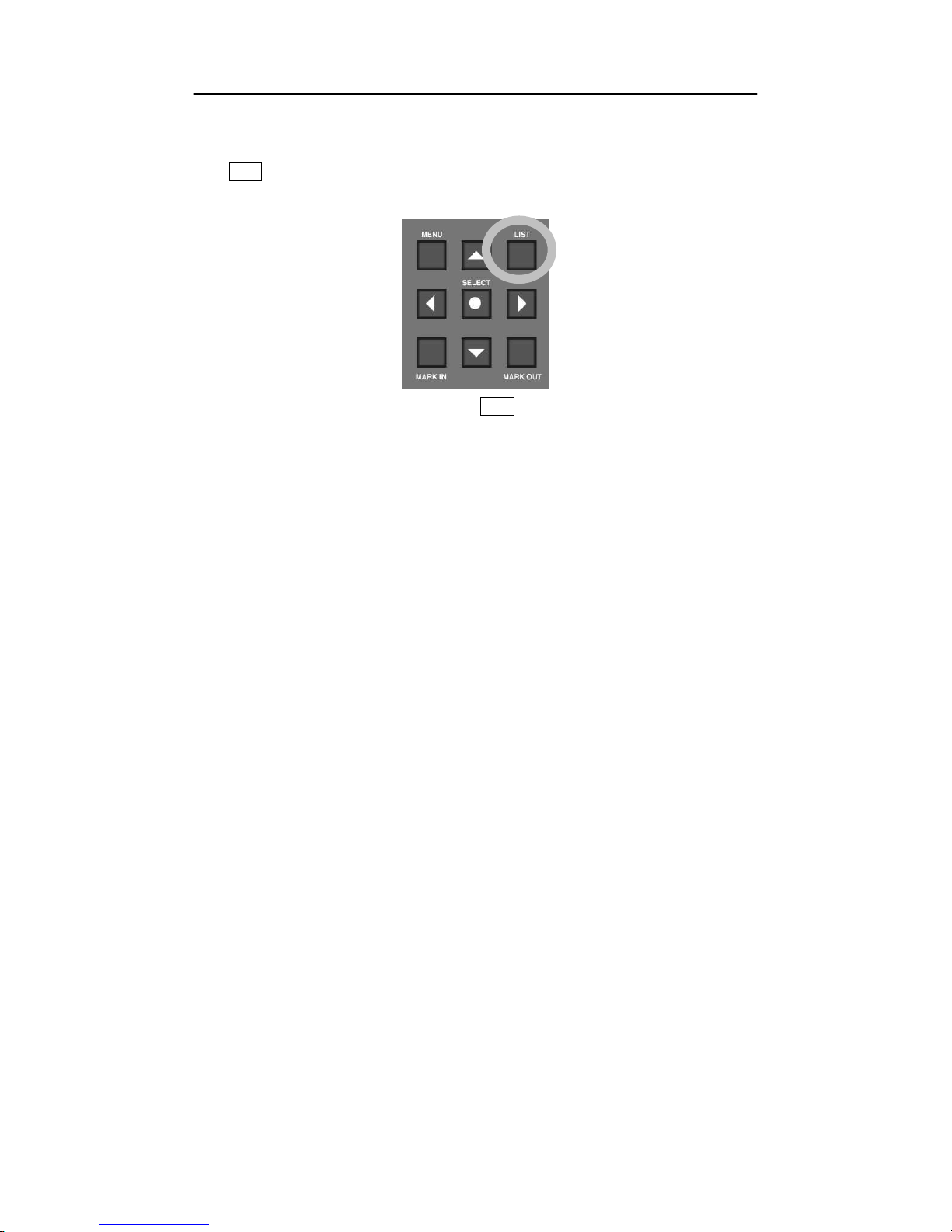
6.7 Play
-
List
Press
LIST button on the
B-DVR front panel, then the Play
-
List Menu(refer to
[Picture
6.
13])
which you can setup the whole MPEG
-
2 file saved in the
B-DVR displays.
[Picture
6.12]
LIST
button
There are 5 commands of the Play
-
List Menu as follow
ings :
· PLAY
:
command to play the selected Play
-
List.
· EDIT
:
command to edit the selected Play
-
List.
· NAME
:
command to specify the name of selected
Play-List.
· CLEA
R
:
command to delete the Play
-
List.
· CLIP
:
command to move to Clip
-
List that manages all clips of Hard Disk.

B-DVR MENU
B-DVR User
’
s Guide
50
[Picture
6.13
] Play
-
List Menu Display
6.7.1
General Processing
① Press
LIST button to display Play
-
List
Menu
.
②
Move to the specified item of Play
-
List using
▲
, ▼
button.
.
③
After moving to each command using
◀
, ▶
button, press
SELECT
button to process
the selected command on the item of Play
-
List.
④
Press
LIST button again to finish Play
-
List Menu display.

B-DVR MENU
B-DVR User
’
s Guide
51
6.8 AL
L CLIPS
All the recorded clips of
B-DVR are shown in
[Picture
6.
14].
There is always the item called
ALL CLIPS at No.
0
0 in the Play
-
List.
The item ALL CLIPS means that it includes all the
clips saved in the
Hard Disk
. You can see all t
he saved video source of
B-DVR in saved order,
if selecting the ALL CLIPS item.
[Picture
6.14
] ALL CLIPS Display
In the ALL CLIPS item, only
PLAY
command among “
PLAY
”,
“
EDIT
”, “
NAME
” and
“
C
LEA
R
” activates. In
PLAY
command processing, it plays without waiting status unlike the
items of other Play
-
List.
However the latest re
corded file appears close to No.00. Although
ALL CLIPS that was recorded in previous times cannot view when it is played after DELETED
from the Clip in the Clip
-
List, it may appear on the display.
The items from No.01 to No.
2
9
of the Play
-
List can proces
s all the commands of “
PLAY”
,
“EDIT”
, “
NAME”
and “
CLEAR
”.
In the Play command processing, the item is on waiting status and starts to play pressing
PLAY
button.
The information about the total size of installed H
ard Disk
(total : 37GB in
[Picture
6.
14]
) and
the usable size of
Hard Disk
storage (free 34GB in
[Picture
6.
14]
) are displayed in the ALL
CLIPS display.

B-DVR MENU
B-DVR User
’
s Guide
52
6.9 Playing the Play
-
List
You can make total of 29 play lists except
ALL CLIPS
and
ALL PLAYLISTS
category
.
Y
ou can edit from all 29 saved different clips from the lists from 01
-
29 you can execute
“
PLAY
”, “
EDIT
”
, and
“
CLEAR
”, “
CLIP
”.
[Picture
6.15
] Select Play
-
List “PLAY
” command
If you select any of the clips from 01
-
29, except
“
ALL CLIPS
” and
“
ALL PLAYLISTS
”
, you
can view the file size for each selected clips. [Picture
6.
15] shows that 134Mbytes are being
used.
6.9.1
Play Command
①
Press
LIST button, Play
-
List Menu will pop up.
②
Use ▲
, ▼
button to move up and down to choose to play any Play
- Lists from 00 ~ 30
Play-List as shown in [ Picture 6.15], it chose
“
DARIM
” for your example.
③
You can use
◀
, ▶
buttons for p
lay to select the location where to play, as it is shown
in [Picture 6.15].
④
Press
SELECT
button to
PLAY
in any selected from the play
–
list.
⑤
When
PLAY
command is being activated, Play
-
list Menu will disappear automatically and
at the same time the screen w
ill show the video in Pause mode to be ready to play from the
paused video screen.

B-DVR MENU
B-DVR User
’
s Guide
53
⑥
Press
PLAY
button to play the video.

B-DVR MENU
B-DVR User
’
s Guide
54
6.10
Playing the ALLPLAYLISTS
There is always the item called ALL PLAYLISTS at No.30 in the Play
-
List. The item ALL
PLAYLISTS means tha
t it includes all the Play
-
Lists saved in the Hard Disk. In the ALL
PLAYLISTS item, only
PLAY
command among
“
PLAY
”,
“
EDIT
”, “
NAME
” and “
CLEAR
”
activates.
[Picture
6.16
] ALL PLAYLISTS
“
PLAY
” command
6.10.1
Play Com
mand
①
Press
LIST button, Play
-
List Menu will pop up.
②
Use ▲
, ▼
button to move up and down to choose to play ALL PLAYLISTS.
③
You can use
◀
, ▶
buttons for play to select the location where to play, as it is shown
in [
6.16].
④
Press
SELE
CT button to
PLAY.
⑤
When
PLAY
command is being activated, Play
-
list Menu will disappear automatically and
at the same time the screen will show the video in Pause mode to be ready to play from the
paused video screen.
⑥
Press
PLAY
button to play the video.

B-DVR MENU
B-DVR User
’
s Guide
55
6.11
Editing Play
-
List
From the Play
-
List, you can select one Clip to group the related videos to make the one specific
Clip to play repeatedly and
continuously
.
[Picture
6.17
] Select Play
-
List “EDIT
” Command
6.11.1
EDIT Command
①
Press
LIST button and Play
-
List Menu to show up on the screen.
②
Use ▲
, ▼
button to select any numbers from 01 ~ 29(Except ALL CLIPS and ALL
PLAYLISTS) and move to any of the Play
-
List to
EDIT.
Example in [Picture
6.
17] it
selected
“
DARIM
”.
③
In order to
EDIT
Use ◀
, ▶
button to select
EDIT
as shown in [Picture
6.
17].
④
Press
SELECT
button to
EDIT
in selected Play
-
List.

B-DVR MENU
B-DVR User
’
s Guide
56
[Picture
6.18
] Play
-
List for Editing display
⑤
When
EDIT
command is executed, Play
-
List Menu will disappear automatically and the
display will change to Play
-
List Edit as shown in the [Picture
6.
18]. Use
◀
, ▶
button
to select
“OK”, “
EDIT
”, “UP”, “
DOWN
”,”
DELETE
” in the Play
-
List to locate to place
in designated Clip.
Each command Explanations are in the followings :
· OK
: After Editing finished, move back to Play
-
List Menu.
· EDIT
: Selecting or changing the related Clip from th
e Clip
-
List.
· UP
: Move upward the related Clip
· DOWN
: Move downward the related Clip
· DELETE
: Delete the related Clip from the Clip
-
List
⑥
Select
EDIT
from the commands above and use
▲
, ▼
button to located the new Clip
in the Clip
-
List or you can choose to change the Clip if desired. Refer to [Picture
6.
19].

B-DVR MENU
B-DVR User
’
s Guide
57
[Picture
6.19
] Play
-
List’s Clip for Editing Display
⑦
Select the
new location of the Clip and press
SELECT
button.
⑧
After checking the Changed Clip, select
OK
to go back to Play
-
List Menu.
⑨
After finishing editing, if you want to check the Clips from the Play
-
List, go to Play
-
List
Menu and use
◀
, ▶
button to select
PLAY
and press
SELECT
button.
⑩
The edited Play
-
List is ready to play. Press
PLAY
button to check to view.

B-DVR MENU
B-DVR User
’
s Guide
58
6.12
Changing names of the Play
-
List
The name of Play
-
List can be changed easily except
“
ALL CLIPS
” and
“
ALL PLAYLISTS
”.
The maximum 12 characters can be us
ed including alphabet letters and numbers. If the name
is not valid or if the Clip is deleted from the Play
-
List, the clip
“
PLAYLIST #
” clip name will
appear.
[Picture
6.20
] Changing the name of the Clip in Play
-
List
6.12.1
NAME Command
①
Press
LIST button. Play
-
List Menu will appear.
②
Use ▲
, ▼
button to select from 01 ~ 29 (Except ALL CLIPS and ALL PLAYLISTS).
For example in [Picture
6.20] , it selected
“
DARIM
”.
③
In order to command
NAME
, use
◀
, ▶
button as it is shown in the [Picture
6.
20],
move to
NAME
location
④
If
NAME
command is selected,
“
D
ARIM
” there will be a square location where you can
edit. Use
▲
, ▼
button t
o move each characters to change of the NAME. Please
move to the characters you want to change, as it is shown in picture [Picture
6.
20]
“D”.
⑤
Press
SELECT
button to execute selected
NAME
command from the Play
-
List.

B-DVR MENU
B-DVR User
’
s Guide
59
[Picture
6.21
] Displaying for Changing the Name
⑥
If
NAME
command is executed, Play
-
List Menu will appear with selection of characters,
as shown in [Picture
6.
21]. Use
▲, ▼
buttons and
◀, ▶
buttons to select characters
or numbers.
⑦
To finish press
SELECT
button.
⑧
The new characters or numbers will appear in the Play
-
List Menu.

B-DVR MENU
B-DVR User
’
s Guide
60
6.13
Deleting the Clip from the Play
-
List
Any saved Clips in the Play
-
List can be deleted easily. It is not about deleting the content of
Clip of the
B-DVR b
ut deleting the content information of Clip of the Play
-
List.
[Picture
6.22
] Deleting Play
-
List Display
6.13.1
CLEAR Command
①
Press
LIST button to show Play
-
List Menu.
②
Use ▲
, ▼
button from 01 ~ 29 (except ALL CLIPS and ALL PLAYLISTS). Move
to the number where you want to give
CLEAR
command from 1
-
9 as shown in [
Picture
6.22] “
DARIM
” is selected.
③
To
CLEAR
, use
◀
, ▶
button as it is shown in [Picture 6.22]
and place
CLEAR
command.
④
Press
SELECT
button to execute CLEAR the clips from the Play
-
List.

B-DVR MENU
B-DVR User
’
s Guide
61
[Picture
6.23
] Clear C
ontent Display
⑤
If
CLEAR
command executed, the confirmation question will pop up in the Play
-
List
Menu as it is shown in [Picture 6.23]
. Use
▲
, ▼
button to select to cancel
CLEAR
by selecting
“NO”
, to continue
CLEAR
, select
“
YES
”.
⑥
Press SELECT
button a
fter confirmation.
⑦
If
CLEAR
command is executed, the Clip will be cleared from the Play
-
List and
“
PLAYLIST #
” clip names will appear.

B-DVR MENU
B-DVR User
’
s Guide
62
6.14
Managing Clip
-
List
In Play
-
List Menu, Clip Menu is included to manage the information of the
Clip
. All the
Clips wh
ich are included in the Clip
-
List can be inserted by using
RECORD
button to make
MPEG
-
2 file or copy MPEG
-
2 file into
B-DVR Hard Disk through
B-DVR Desktop program.
You can view Clip
-
List, from Play
-
List Menu by selecting
CLIP
.
In the Clip
-
List Menu, th
ere are 4 different commands.
· PLAY
: Play the selected Clip.
· NAME
: Name the selected Clip.
· DEL
: Delete the selected Clip.
· DELALL
: Delete Every Clips
[Picture
6.24
] Clip
-
List Menu Display
6.14.1
Overall Execute Su
mmary
①
Press
LIST button to have Play
-
List Menu.
②
Use ◀
, ▶
button and select the
CLIP
and press
SELECT
button as it appears in Clip
-
List Menu in [Picture 6.24].
③
To get out of Clip
-
List Menu, Press
LIST button once to go to Play
-
List Menu. To get out
of Play
-
List menu, Press
LIST button once more.

B-DVR MENU
B-DVR User
’
s Guide
63
6.15
Play Clip
-
List Items
You can make up to 300 different items in Clip
-
List Menu. You can execute
“
PLAY
”
,
“
NAME
”, ”
DEL
”, “
DELALL
” for every item in Clip
-
List.
[Picture
6.25
] Select
“
PLAY
” in CLIP
-
LIST.
In addition, for all the items, if one item is selected, the date and the size of the Clip can be seen
on the display. In [Picture 6.25], it is displaying that the item was recorded on June 26
th
, 2003
and 21Mbytes data are
being used.
6.15.1
PLAY Command
①
Press
LIST button to go to Play
-
List Menu.
②
Use ◀
, ▶
button to place
CLIP
command.
③
Press
SELECT
button to go to Clip
-
List Menu.
④
In Clip
-
List Menu, use
▲
, ▼
button to select the item to give
PLAY
command from
00 ~ 99. For example, in [Picture 6.25]
“
FASHIONM10
” is selected.
⑤
To
play use ◀
, ▶
button to
move to
PLAY
like in [Picture 6.25].
⑥
Press
SELECT
button to
PLAY
the selected Clip.
⑦
When
PLAY
executed, Clip
-
List Menu automatically disappear and selected Clip is ready
to play from start from the beginning of the clip from the pause mode.
⑧
Press
PLAY
butt
on to play the video

B-DVR MENU
B-DVR User
’
s Guide
64
6.16
Change the names of the Clip
-
List items
It is possible to change the names of the saved items from the Clip
-
List. Maximum of 12
characters can be used including alphabets and numbers.
[Picture
6.26
] Change the names of the Clip
-
List items
6.16.1
NAME Command
①
Press
LIST button to go to Play
-
List Menu.
②
Use ◀
, ▶
button to place
CLIP
command.
③
Press
SELECT
button to go to Clip
-
List Menu.
④
In Clip
-
List Menu, use
▲
, ▼
button to select the
item to give
PLAY
command from
00 ~ 99. For Example, in [Picture 6.26]
“
FASHIONM10
”
is selected.
⑤
To select
NAME
, use ◀
, ▶
button as [Picture 6.26]
to place
NAME
.
⑥
When cursor is placed on
NAME
, editing box will appear for you to change the names as
shown
in the [Picture 6.26],
“
0
217_155602
”
. Use
▲
, ▼
button to move to each
different characters. Move to the character you wish to change. For example, in [Picture
6.26] “0” is selected.
⑦
Press
SELECT
button to place the name that had created in the Play
-
List.

B-DVR MENU
B-DVR User
’
s Guide
65
[Picture
6.27
] Display for changing the names
⑧
If
NAME
command is executed, selected characters are displayed in Clip
-
List Menu to
choose (Refer to [Picture 6.27]). Use
▲
, ▼
button and
◀
, ▶
button to char
acters
or numbers which you wish to change.
⑨
After finishing press
SELECT
button.
⑩
The newly changed characters or numbers will be appeared in the Clip
-
List Menu.

B-DVR MENU
B-DVR User
’
s Guide
66
6.17
Delete Clip
-
List Items
It is easy to delete the saved clips from the Clip
-
List. There are
two commands for deleting
Clip-List Items,
“
DEL
” command is to delete only selected items from the Clip
-
List, and
“
DELALL
” is to delete all clips in Clip
-
List in
B-DVR
.
These two commands delete the
clips from the hard disk, so any important or
necessar
y clips are always suggested to back
up to PC hard disk using B
-
DVR Desktop program. Once it is deleted, the clips can
never be restored.
[Picture
6.28
] Display for deleting from the clip items from the Clip
-
List
6.17.1
DEL(Delete), DELALL(Delete All) Command
①
Press
LIST button to go to Play
-
List Menu.
②
Use ◀
, ▶
button to place
CLIP
command
③
In Clip
-
List Menu, use
▲
, ▼
button to select the item to give
DEL
or
DELALL
command from 00~99. For example, in [Picture 6.
28] “
0217_155602
”
is selected.
④
To
DEL
or
DELALL
use ◀
, ▶
button to move to
DEL
or
DELALL
like in [Picture
6.28].
⑤
Press
SELECT
button to delete for
DEL
for selected Clip and
DELALL
for deleting all
clips.

B-DVR MENU
B-DVR User
’
s Guide
67
[Picture
6.29
] Display for Deleting
Clip
⑥
If
DEL
or
DELALL
command has executed, the confirmation question will pop up in the
Play-List Menu as it is shown in [Picture 6.29]. Use
▲
, ▼
button to select to
cancel
DEL or DELALL
by selecting
“NO”
, to continue
DE
L or DELALL
, select
“
YES
”
Warning : All deleted clips CANNOT be restored.
⑦
Press SELECT
button to finish.
⑧
DEL
or
DELALL
command is executed Clips from the Clip
-
List are deleted.

B-DVR MENU
B-DVR User
’
s Guide
68

B-DVR User
’
s Guide
69
7 B-DVR DESKTOP SOFTWARE
Darim is providing with
B-DVR Desktop software t
o install in P.C. You must install this software to
use MPEG 2 file that had been recorded and played from
B-DVR in your PC. The Hard Disk that
had been recorded and played in
B-DVR is set as
MASTER
mode so before connecting to the PC,
check the jumper
setting in IDE mode. Default is set as either MASTER or SLAVE mode.
Depending on how IDE is stored in PCs select appropriate mode, MASTER or SLAVE.
You cannot use the file more than 4GB in FAT16 and FAT32 Operating system in Microsoft PC. In
additio
n, it is optimized play in over 4GB file supported NTFS format Hard Disk in Windows 2000 or
Windows NT.
Every MPEG
-
2 file saved into the Hard Disk in
B-DVR can be copied into PC using
B-DVR Desktop
software and MPEG 2 file saved into PC can be copied into
B-
DVR hard Disk. When
B-DVR
Desktop software is used, MPEG
-
2 file from
B-DVR Hard Disk can be played in PC and you can edit
and manage the Play
-
List and Clip
-
List in your PC.
The advantage of using Hard Disk of
B-DVR
is that any Clip that has been dele
ted appeared as free
space to optimize the function of Hard Disk. You can add Clip in your PC using
B-DVR Desktop
software for any MPEG
-
2 file. However, in some occasions, some of the clips which had not been
recorded nor added through
B-DVR but in PC
using
B-DVR Desktop software, PLAY or Mark In/Out
would not be able to function in B
-
DVR.

B-DVR DESKTOP SOFTWARE
B-DVR User
’
s Guide
70
7.1 B-DVR Desktop Software
In order to install B
-
DVR Desktop software which is included in B
-
DVR package, run the B
-
DVR Desktop.exe then it starts to install.
[Picture
7.1
] B-DVR Desktop S/W Installation
It is possible to access to the B
-
DVR Hard Disk on PC via B
-
DVR Desktop when you
finish the installation B
-
DVR Desktop software.
After switching off power, make sure that the Hard Disk
’
s jumper setting
in order not to
collide with other IDE device as the B
-
DVR Hard Disk is in set up in MASTER.
Although Hard Disk doesn
’
t appear on the Windows Explore, it must be
recognized
in
CMOS Setup.
In general, run
‘
Start Program
→
B-DVR Desktop
→
B-DVR Desktop
’
, then
B-
DVR
Desktop software is run.
There are 2 items in B
-
DVR Desktop S/W, which are Play
-
List and Optimization.

B-DVR DESKTOP SOFTWARE
B-DVR User
’
s Guide
71
7.2 Clip-List Menu
These are the Clip
-
List menu which have functions like PLAY, NAME, DEL in B
-
DVR ( Refer
6.14 ).
[
Picture
7.2
] Clip
-
List Menu
Save Clip to Local HDD
Save the selected Clip of B
-
DVR Hard Disk to PC
Hard Disk as *.mpg(MPEG
-
2) file.
It can be saved by double click the selected Clip.
Rename
Change the name of s
elected Clip.
Delete Clip
Delete the selected Clip.
Delete All Clips
Delete the all Clip.
Play
Play the selected Clip.
Add Clip to B
-
DVR HDD
Add *.mpg(MPEG
-
2) file in PC Hard Disk to B
-
DVR Hard Disk. It can be added by dragging a file
with a mouse.

B-DVR DESKTOP SOFTWARE
B-DVR User
’
s Guide
72
7.2.1
Mar
king and Play a Clip on B
-
DVR HDD with MPEG
-
2 Viewer
[Picture
7.3
] MPEG2 Viewer
Mark In
Indicate
the starting part.
Mark Out
Indicate the ending part.
Crop
Operate Marking.
Snap Shot
Save the selected picture of B
-
DVR Hard Disk to PC
Hard Disk as *.bmp(BMP) or *.jpg(JPEG) file.
Play
Play
the selected Clip.
Stop
Stop the played Clip.
Close MPEG2 Viewer
Close the MPEG2 Viewer window.

B-DVR DESKTOP SOFTWARE
B-DVR User
’
s Guide
73
7.3 Play
-
List Menu
These are Play
-
List menu which have functions like EDIT, NAME, CLEAR.
[
Picture
7.4
] Play
-
Lis
t Menu
Rename
Change the name of Play
-
List.
Delete Play
-
List
Delete Play
-
List.
Save Clips to Local HDD
Save Clips in the selected Play
-
List of B
-
DVR Hard
Disk to PC Hard Disk as *.mpg(MPEG
-
2) file.

B-DVR DESKTOP SOFTWARE
B-DVR User
’
s Guide
74
7.4 B-DVR Hard Disk Optimization
The optimizat
ion is in Item.
Press
icon, then you can move to the window for optimization of Hard Disk.
Press
icon to go back to Play
-
List.
[
Picture
7.5
] Optimization
The space of deleted clips may be remained as occupied
in the Hard Disk
. B
-
DVR uses the
data in order and only has the information of deleting of Clip. You must optimize to use
Hard Disk effectively.

B-DVR DESKTOP SOFTWARE
B-DVR User
’
s Guide
75
7.5 Setti
ngs
Using the desktop software of B
-
DVR, the user enables to change the setting of menu.
To change the setting of menu, press “Setting” tab on the left side of desktop software.
[Picture
7.6
] Settings
7.5.1
B-
DVR Settings
If the user selects the “B
-
DVR Settings” icon on the left side, the following dialogue will be
shown.
In the dialogue, the user can set up for the values of DVR, screen and video setup.
When “default” button is pressed, it would change to defau
lt setting like “Factory Setting”.
On the list box of the menu, the user can select the value and press the “OK” button to apply the
setting.

B-DVR DESKTOP SOFTWARE
B-DVR User
’
s Guide
76
[Picture
7.7
] B-DVR Settings
7.5.2
Scheduler
When “Scheduler” icon is selected, the following dialogue will be shown.

B-DVR DESKTOP SOFTWARE
B-DVR User
’
s Guide
77
[Picture
7.8
] Scheduler
[Picture
7.9
] Sche
dule Setting
The user can setup the menus including the Mode, Starting Time, Ending Time, Play list/Bitrate

B-DVR DESKTOP SOFTWARE
B-DVR User
’
s Guide
78
by double
-
click of desired item as shown in the
[Picture
7.9]
[Picture
7.10]
Scheduler Menu
Clear Selected Schedule
Deletes the selected schedule
Clear Schedule From Selected
Deletes the schedule list from the selected one to the
last one.
Clear All Schedule
Deletes all schedule list
Delete
Same as “Clear Selected Schedule
” Menu
Save To File
Saves the schedule list as a file.
Load From File
Load the schedule list from a schedule file which is
previously saved.
OK
Applies the setting value of schedule
Cancel
Exits from the dialog box without applying new
setting value
of schedules

B-DVR User
’
s Guide
79
8 HARD DISK
MANAGEMENT AND HOW TO USE
8.1 B-DVR
Hard Disk
Jumper Setting
The Hard Disk can be used in B
-
DVR is one of most general IDE type hard disk.
The general IDE Type hard disk doesn
’
t need any special format or changing to file
system
to use easily by inserting to Hard Disk rack. Make sure that the jumper
setting of Hard Disk must be setup in Master mode among Master/Slave modes. If
it is in Slave mode or jumper setting is not right, the message
“
Err 01
” is displayed in
the VFD of
front panel when switching on power of system.
8.2 How to use B
-
DVR HDD on general PC
Make sure that you use Software provided by Darim Vision Co. Ltd. in order to use
B-DVR HDD in general PC. If not, all the information of HDD can be deleted.
The HDD u
sed in general PC can be used in B
-
DVR right away by installing it to
HDD rack in MASTER mode setup.

HARD DISK MANAGEMENT AND HOW TO USE
B-DVR User
’
s Guide
80

B-DVR User
’
s Guide
81
9 TROUBLESHOOTING
B-DVR, a MPEG
-
2 capture device is run by separate S/W with no related with Windows and it
is designed not to collide with other devic
e if possible. Most troubles can be occurred when
unskilled operation or unbalanced situation of system is run.
9.1 How to solve the
trouble
of B
-
DVR
·
How to solve that video Clip of B
-
DVR is not displayed
The trouble happens when setting up hardware and Me
nu of B
-
DVR. B
-
DVR Video Input
supports 2 types such as Composite and S
-
Video and Video Output supports 4 types such as
Composite, S
-
Video, RGB and Component.
Make sure to set up Video Input and Video Output properly in Video Set up Main Menu.
When new Ha
rd Disk is connected to B
-
DVR, Video Input supports Composite and Video
Output supports S
-
Video(Composite). Refer to
6.4 Video Setup.
·
How to solve that Playlist of B
-
DVR is not displayed
Make sure that clips are set up in the
Play-List item in the List menu. If the Clip is not
inserted in Play
-
List, that Play
-
List can be played.
·
How to recover the deleted Clip in Play
-
List
The Clips in HDD are not deleted really although it is deleted from the Play
-
List. But the
Clips del
eted on the Clip
-
List can not be recovered as it is deleted from the HDD.
Therefore note that you must be careful to delete Clip on the Clip
-
List.
·
How to do when the HDD used in B
-
DVR can not be used in PC
Make sure that you change the jumper(Refer to H
DD information) of HDD type to Slave
mode when you want to use B
-
DVR HDD in general PC. The OS(Operating System) of
B-DVR is different from the OS of general Windows or Dos, so B
-
DVR HDD itself is not
booted in general PC. You must use the S/W provided
by Darim Vision Co. Ltd. in order
to use B
-
DVR HDD in general PC.
You can use the HDD used in
general
PC in the B
-
DVR by installing hard rack. Darim
Vision is not responsible for the damage of HDD caused by customer
’
s fault. You must
inquire to the de
pt. of customer support of Darim Vision Co. Ltd. about the change of HDD.
·
When the recording time is over 13 hours

TROUBLESHOOTING
B-DVR User
’
s Guide
82
The present B
-
DVR decides the recording time of one Clip depending on the remaining
space of HDD. It is possible to record for a long tim
e if the space of HDD is enough. But
do not try to record one Clip for over 13 hours. When you play the Clip recorded for over
13 hours, the displayed time in VFD of front panel is
initialized
to 00:00:00 after the time of
13:14:34. It is caused by the
trouble of MPEG
-
2 Encoder of B
-
DVR. Therefore it is
designed to record for less 13 hours. Refer the messages in recording from [
9.2 message
occurred in B
-
DVR activation].
·
When the deleted Clip plays All Clips in playback m
ode
You can PLAY, NAME, DEL and ALLDEL all Clips in Clip
-
List. If you record at the
latest or add MPEG
-
2 file using B
-
DVR Desktop software, it is located in the closest to
Clip-List No.00. The Clip of the last no is the recorded Clip at the first time.
Though
it is deleted once, it can be appeared in the Play
-
List by selecting All Clips to playback.
It is suggested to
optimize
using B
-
DVR Desktop.
·
How to do when less storage space in HDD
B-DVR saves Clips in order when recording or adding Clips usi
ng B
-
DVR Desktop.
Therefore, it can be happened to have less remaining space of HDD than calculated from the
whole space.
In order to use Hard Disk effectively, it is suggested to optimize HDD by connecting to PC
and using B
-
DVR Desktop
·
In case there i
s incorrect Time
-
Code in front VFD panel
For User
’
s friendly, when playing or recording MPEG
-
2 file in B
-
DVR, Time
-
Code
indicates in VFD. Any
information
related in Time
-
Code in current used MPEG
-
2 file in
B-DVR includes maximum about 13 hours. There ar
e 2 cases of initialization of Time
-
Code
of B-DVR. When user records and playback over 13 hours, the value of Time
-
Code
converts to the initialized value. Another case, it happens in pause even though user
recorded under 13 hours. According to these p
henomena, the real recording time cannot
be same
with the
Time-Code in VFD. It is caused by the inaccurate calculation of Time
-
Code information in MPEG
-
2 file and cannot be fixed under the existing system.
However, the related Time
-
Code information in
VFD supports to search image and
find the general location. User can use this Time
-
Code information for Mark In/Out
and simple reference.

TROUBLESHOOTING
B-DVR User
’
s Guide
83
9.2 Messages occurred B
-
DVR activation
·
When switching on B
-
DVR
message
symptom
solution
“
Rec:LoadClip error
”
Cannot r
ead Information from HDD
Make sure HDD jumper is in MASTER
mode and reboot B
-
DVR again. The
same symptom is occurred again, set up
HDD in Low Level Format. Needs A/S
of HDD when still having problem.
“
Please, backup clips
”
HDD is not compatible with olde
r B
-
DVR’s HDD.
Clips were made in older B
-
DVR, HDD
is not
compatible
with used before.
Please save clips by using B
-
DVR
desktop software then make all clips in
B-DVR HDD to use properly.
·
When pressing Menu button
“
Config save error!!!
”
“
Config read error
!!!
”
Cannot read or save Information
from HDD
Make sure HDD jumper is in MASTER
mode and reboot B
-
DVR again. The
same symptom is occurred again, set up
HDD in Low Level Format. Needs A/S
of HDD when still having problem.
·
Messages in palying
“
No MPEG Cli
ps”
No saved MPEG
-
2 video clip in HDD
“
Ready
”
Being ready for playing MPEG
-
2 video
clip
"Begin
ning
of
clip"
Located in the beginning position of
MPEG
-
2 video clip
"End of
clip"
Located in the last position of MPEG
-
2
video clip
"Forc
ed Stop"
Play mo
de is forced to stop due to error
of B-DVR
·
Messages in recording
"End of HDD"
Full of MPEG
-
2 video clips in HDD
“Reached max
-
time of
Stop recording due to over 13 hours

TROUBLESHOOTING
B-DVR User
’
s Guide
84
a clip”
recording.
"
Reached m
ax.
number
of clips
"
100 MPEG
-
2 video clips in HDD
"File Writing Error!!!"
"Writ
ing e
rror"
"File System
e
rror"
Error in HDD.
Make sure HDD jumper is in MASTER
mode and reboot B
-
DVR again. The
same symptom is occurred again, set up
HDD in Low Level Format. Needs A/S
of HDD when still having problem
"Re
cord
ing e
rror"
Error in Streaming board.
Reboot B
-
DVR and record. Ask the
nearest dealer when still having
problem.
"
No input signal
"
Try to recording without Video In
Connect camera to Video In and
confirm the power.
"
Failed to save clip
”
Cannot record
ing 1) Error in HDD
Make sure HDD jumper is in MASTER
mode and reboot B
-
DVR again. The
same symptom is occurred again, set up
HDD in Low Level Format. Needs A/S
of HDD when still having problem
2)
No
Video In
.
3) Recording Time
is less than 1
second.
4) Over 100 clips or HDD is full.
·
Messages in
BookMark
"
Failed to save
b
ookmark"
Can not save the information of
BookMark
.
Press
Stop button to finish Play and
bookmark again in the same position.
"Book
m
ark
doesn
’t
e
xist"
BookMark
does not exist.
"IsBoo
ked r
ead
error"
"GetAllBookMarkClip
r
ead error"
Failed to read the information of
BookMark
in HDD
.
·
Messages in
Mark
In/Out
"Marking
failed"
Failed
Marking
. Press S
top button to finish
Play mode
and mark again in the same position of

TROUBLESHOOTING
B-DVR User
’
s Guide
85
marking.

TROUBLESHOOTING
B-DVR User
’
s Guide
86
9.3 Upgrade
Information and Technical Support
The applied program and software of B
-
DVR is upgraded continuously. You can download
the latest software and applied program from the Darim Vision Homepage.
WWW Site
http://www.darim.com
http://www.darim.co.kr
FTP S
ite
ftp://ftp.darvision.com
Phone
+82-42-601-1311
Fax
+82-42-861-2484
Note)
The technical support staff of Darim Vision
will be
able to help you faster with great
efficiency if you include the following information in the description of your questio
n
or problem.
1) Date of purchasing B
-
DVR
2) The version of B
-
DVR
3) Serial No.
4) All the details of errors

TROUBLESHOOTING
B-DVR User
’
s Guide
87
Note)
The improvement of design and specification can be changed as upgraded without
prior notification.
 Loading...