

Darfon H5001 Installation Manual
INSTALLATION MANUAL
H5001 HYBRID INVERTER

INSTALLATION MANUAL H5001 HYBRID INVERTER
TABLE OF CONTENTS
IMPORTANT SAFETY WARNINGS .................................................................................................... 3
INTRODUCTION ................................................................................................................................... 4
Product Overview ................................................................................................................................ 4
MOUNTING THE INVERTER ...............................................................................................................5
Installing the Inverter onto the Wall ............................................................................................... 5
PV MODULE (DC) CONNECTION .....................................................................................................6
Connecting the PV Arrays ................................................................................................................ 6
GRID (UTILITY) CONNECTION .......................................................................................................... 7
Connecting to the Grid/Utility ........................................................................................................... 7
BATTERY CONNECTION AND CHARGING REQUIREMENTS ....................................................8
Connecting the Batteries .................................................................................................................. 8
Battery Charging Requirements ...................................................................................................... 9
LOAD (AC OUTPUT) CONNECTION ............................................................................................... 11
Connecting to the Load ..................................................................................................................... 11
OPERATION AND DISPLAY PANEL ............................................................................................... 12
Display Panel Overview .................................................................................................................... 12
Starting the System ............................................................................................................................ 12
Stopping the System ......................................................................................................................... 12
LCD Screen – Icons and Pages ..................................................................................................... 13
Mode Rule Definition ......................................................................................................................... 14
System Settings .................................................................................................................................. 15
Warning and Fault Definition........................................................................................................... 17
GENERATOR [OPTIONAL] ................................................................................................................ 19
Generator Sizing ................................................................................................................................. 19
Automatic Start Generator ............................................................................................................... 19
Generator Application Schematic .................................................................................................. 19
CONFIGURING THE HARDWARE .................................................................................................. 20
Connecting to the hardware .......................................................................................................... 20
USE APPLICATION SOFTWARE MODIFIES PARAMETERS ..................................................... 22
Preparation .......................................................................................................................................... 22
Connecting to the application software and modifies parameters ..................................... 22
Parameters setting tables ............................................................................................................... 25
MAINTENANCE & CLEANING ........................................................................................................ 26.
Wiring Diagram .................................................................................................................................. 26
SPECIFICATIONS .............................................................................................................................. 27
GRID SUPPORT PARAMERTERS ................................................................................................... 28
5-YEAR LIMITED WARRANTY ........................................................................................................ 30
Rev.1 ©2018 Darfon Electronics Corp. 2 | Page
INSTALLATION MANUAL H5001 HYBRID INVERTER
WARNING. This indicates the risk of electric shock. The presence of high voltage levels may constitute a risk of injury or death to users
and/or installers.
CAUTION. Before installing and using this inverter, read all instructions and cautionary markings on the inverter and all appropriate
sections of this guide. Installing this inverter by licensed electricians only.
WARNING. Authorized service personnel should reduce the risk of electrical shock by disconnecting AC, DC and battery power from the
reduce this risk. Internal capacitors can remain charged for 5 minutes after disconnecting all sources of power.
WARNING. Do not disassemble this inverter yourself. It contains no user-serviceable parts. Attempt to service this inverter yourself may
WARNING. To avoid a risk of fire and electric shock, make sure that existing wiring is in good condition and that the wire is not
undersized. Do not operate the Inverter with damaged or substandard wiring.
CAUTION. Under high temperature environment, the cover of this inverter could be hot enough to cause skin burns if accidentally
touched. Ensure that this inverter is away from normal traffic areas.
WARNING. To avoid a risk of the inverter damage, make sure that the working areas no metal particle and keep clean around the
working areas.
WARNING. Use only recommended accessories from installer. Otherwise, not-qualified tools may cause a risk of fire, electric shock, or
injury to persons.
CAUTION. Do not operate the Inverter if it has received a sharp blow, been dropped, or otherwise damaged in any way. If the Inverter is
CAUTION. This inverter is not allowed to operate in parallel. Do not parallel connect more than one unit in AC output connector.
Otherwise, it will damage this inverter.
IMPORTANT SAFETY WARNINGS
PLEASE READ ALL INSTRUCTIONS AND CAUTIONARY MARKINGS ON THE UNIT AND THIS MANUAL BEFORE USING THE
INVERTER. AND, STORE THIS USER MANUAL WHERE IT CAN BE ACCESSED EASILY.
This manual is for qualified personnel. The tasks described in this manual may be performed by qualified personnel only.
Safety Symbols
CAUTION. This indicates important information where failure to comply may result in safety hazards or cause damage to this product.
CAUTION. This indicates the risk of a hot surface. The surface may reach a temperature high enough to cause serious burn injuries.
General Precautions
CAUTION. Normally grounded conductors may be ungrounded and energized when a ground fault is indicated.
CAUTION. This inverter is heavy. It should be lifted by at least two persons for the safety.
inverter before attempting any maintenance or cleaning or working on any circuits connected to the inverter. Turning off controls will not
cause a risk of electrical shock or fire and will void the warranty from the manufacturer.
CAUTION. To reduce risk of fire hazard, do not cover or obstruct the cooling fan.
damaged, call for an RMA (Return Material Authorization).
Rev.1 ©2018 Darfon Electronics Corp. 3 | Page
INSTALLATION MANUAL H5001 HYBRID INVERTER
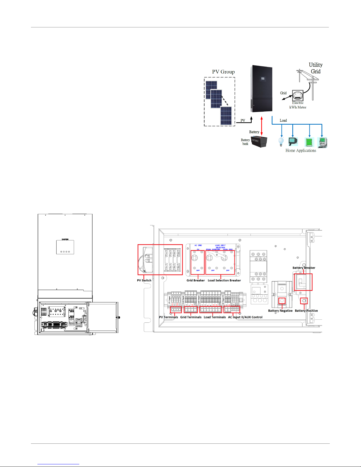
BASIC HYBRID PV STORAGE SYSTEM OVERVIEW
INTRODUCTION
The H5001 hybrid inverter provides power to the essential
load by utilizing power from PV panels, the utility and
batteries. When the PV panels (two string input) generates
enough power, the inverter supports the essential load,
feeds back to the grid and charges the batteries, all at the
same time. When the energy generated by the PV panels is
not sufficient to support the essential load, the inverter takes
power from the utility.
To accommodate various power situations, the H5001 is
designed to handle continuous power from PV panels,
batteries and the utility. When the MPP input voltage from
the PV panels is within the acceptable range, between 250
and 430VDC, the inverter is able to feed the grid and charge
the batteries. This inverter is only compatible with single
crystalline and polycrystalline PV panels, and any other type of PV panels cannot be used.
Notes: When PV input voltage is lower than 250V, the power of the inverter will de-rate. This hybrid inverter has two PV
input.
Product Overview
Distribution Box
A wiring subpanel is pre-assembled at the factory. It consists of breakers, disconnects and batteries paralleled
circuits.
Rev.1 ©2018 Darfon Electronics Corp. 4 | Page
INSTALLATION MANUAL H5001 HYBRID INVERTER
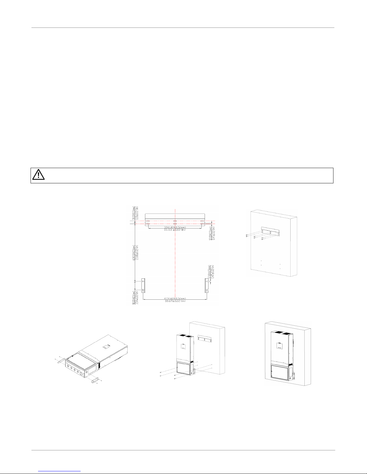
CAUTION. This inverter is heavy (87lb/40kg). Be carefully while lifting and mounting the unit. Installation should be
handled by two people. Do not hang or place additional weight onto the inverter.
MOUNTING THE INVERTER
Before installation, make sure nothing inside the package is damaged. You should have received the following
items in the package: H5001 hybrid inverter, backplate, brackets, screws and this installation manual.
The following considerations must be taken into account before selecting where to install.
• The unit cannot be mounted on flammable construction materials.
• The unit must be mounted to a solid surface.
• The unit should be installed at eye level in order to easily read the LCD display at any time.
• Allow 20cm (8in) of clearance to the sides and 50cm (20in) to the top and bottom of the unit for proper air
circulation to dissipate heat.
• The ambient temperature must be between 0 and 50°C and relative humidity must be between 5 and 85% to
ensure optimal operation. Do not operate where the temperature and humidity are beyond the specified limits.
• The unit has a Pollution Degree rating of PD2. The unit must be mounted in a protected area that is dry, free of
excessive dust and has adequate air flow.
• The unit was designed with an IP20 protection rating and is for indoor applications only.
Installing the Inverter onto the Wall
Step 1. Use the backplate as a
template, and install
anchors as needed.
Note: If installing onto
drywall, Unistrut needs to
be mounted and secured to
two studs in the wall. The
backplate and inverter’s
brackets are secured to the
Unistrut using Unistrut lugs.
Step 3. Install the brackets onto each
side of the inverter.
Step 4. Hang the inverter onto the
backplate.
Step 2. Mount the backplate onto the wall.
Note: Use at least two screws, one on
the left the other on the right.
Step 5. Secure the brackets on
inverters to the wall.
Rev.1 ©2018 Darfon Electronics Corp. 5 | Page
Note: Use at least two screws,
one on each side of the
inverter.
INSTALLATION MANUAL H5001 HYBRID INVERTER
TERMINAL MARK
PV INPUT POWER
TYPICAL AMPERAGE
CABLE SIZE
TORQUE
BEST VMP
VMP RANGE
PV input 1
3.25kW
13A
12 AWG
1.4 - 1.6 Nm
360V
250V - 430V
PV input 2
3.25kW
13A
12 AWG
1.4 - 1.6 Nm
360V
250V - 430V
WARNING. Because this inverter is non-isolated, only two types of PV modules are acceptable: single crystalline and poly
current to the inverter. For example, non-grounded PV modules will cause leakage current to the inverter.
CAUTION. To reduce the risk of damage due to surge, Darfon recommends surge protection between the modules and
the inverter.
CAUTION. Exceeding the maximum input voltage can destroy the unit. Check the PV string voltage before wiring the
connection.
WARNING. Never touch the terminals of the inverter directly. It
at the array not at the inverter.
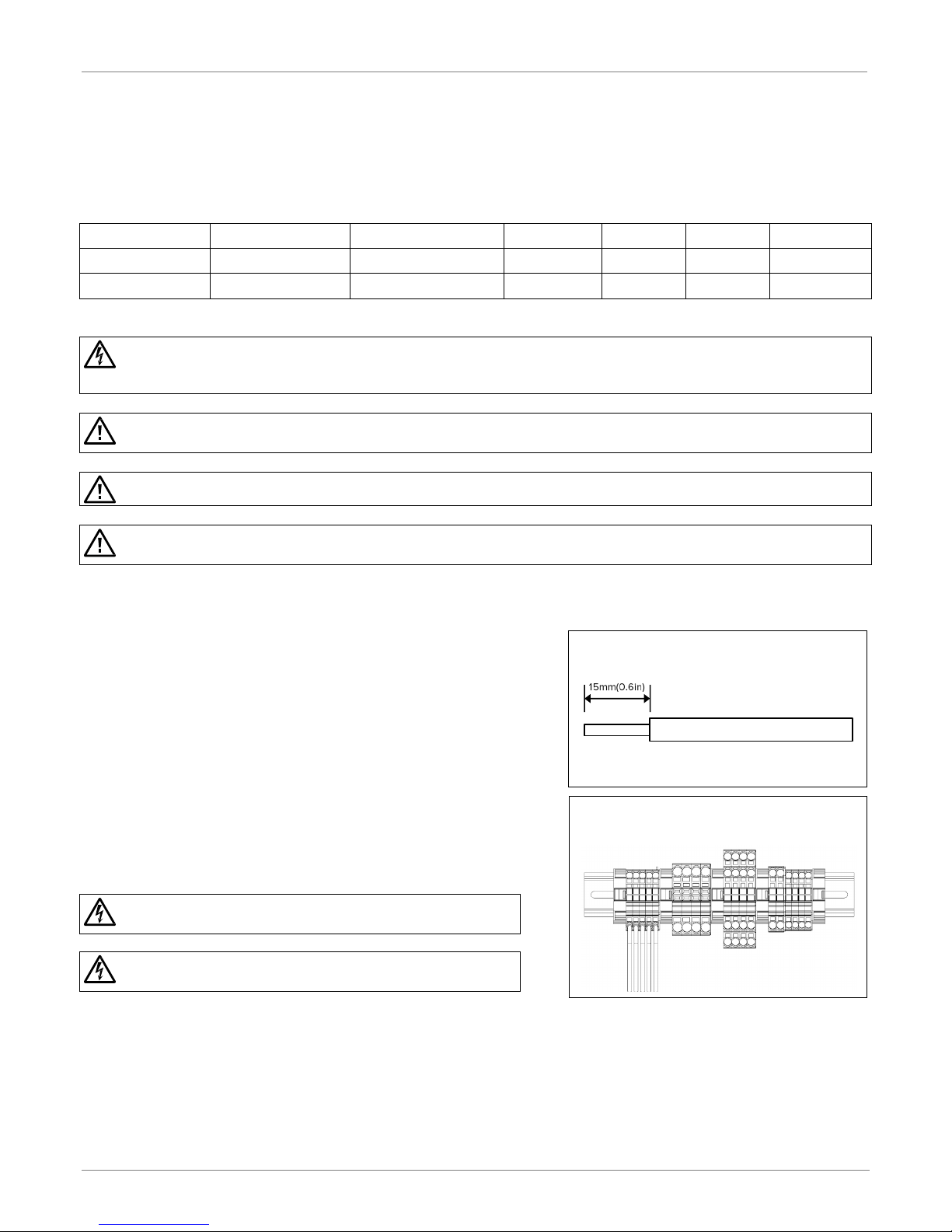
DC CABLE FOR PV CONNECTIONS
PV MODULE (DC) CONNECTION
There is a DC (PV) circuit breaker in the distribution box. This system can connect to two strings of PV modules with
MPPT control. Configure each PV input as recommended in the table below. Vmp is a PV panel’s max power point
voltage. The PV charging efficiency is maximized when the PV system’s voltage is close to Best Vmp.
crystalline with only Class A-rated. To avoid any malfunction, do not connect any PV modules with possibility of leakage
CAUTION. To reduce the risk of injury, use the proper cable size for PV module connection.
Connecting the PV Arrays
Step 1. For each PV input string, make sure the input voltage is between
250VDC and 430VDC, and the maximum current is 13A.
Note: The inverter can still be installed if you are only using
one PV input string.
Step 2. Make sure the circuit breaker is off.
Step 3. Strip 15mm(0.6in) of insulation from each PV cable (PV1+, PV1-, PV2+
and PV2-).
Step 4. Insert the PV cables into the PV quick connect terminals. Make sure
the polarity for each connection is correct; positive to positive and
negative to negative.
will cause lethal electric shock.
WARNING. The final connection for DC strings should be done
CONNECTING TO PV MODULE
Rev.1 ©2018 Darfon Electronics Corp. 6 | Page
INSTALLATION MANUAL H5001 HYBRID INVERTER
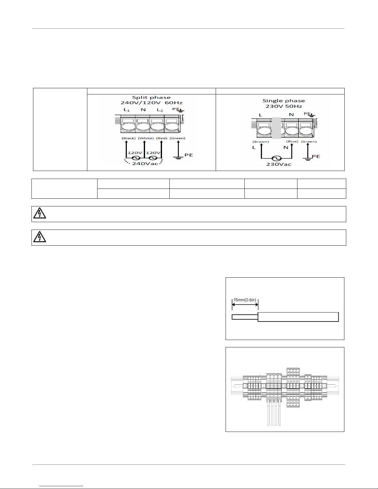
USA: 240V/120V SPLIT-PHASE SYSTEM
EURO: 230V SINGLE PHASE SYSTEM
GRID RATED POWER
NOMINAL VOLTAGE
WIRE SIZE
TORQUE
5KW
230/240 VAC
8 AWG
0.82 Nm
efficient operation to use the appropriate wire for grid (utility) connection.
WARNING. To prevent the risk of electric shock, make sure the ground wire is properly earthed before operating this unit
whether the grid is connected or not.
CONNECTIN G TO AC UTILITY TERMINAL
AC WIRE FOR GRID CONNECTION
GRID (UTILITY) CONNECTION
There is an AC (Grid) circuit breaker in the distribution box. This will ensure the inverter can be safely disconnected
during maintenance and is fully protected from overcurrent of AC input.
AC GRID
UTILITY
TYPE
GRID CONNECTION
WIRING REQUIREMENTS
WARNING. To reduce the risk of injury, use the recommended wire size above. It is very important for system safety and
Connecting to the Grid/Utility
Step 1. Check the grid voltage and frequency with an AC voltmeter. It
should be within the operation AC voltage range of the product’s
specifications.
Step 2. Make sure the circuit breaker is off.
Step 3. For each AC wire, strip 15mm(0.6in) of isolation.
Step 4. Connect the AC wires to the inverter according to the labels
indicated on the terminal block or your grid utility type.
Note: The PE protective conductor (Ground) should be the
first to be connected.
Rev.1 ©2018 Darfon Electronics Corp. 7 | Page
INSTALLATION MANUAL H5001 HYBRID INVERTER
BATTERY POWER
TYPICAL AMPERAGE
BATTERY CAPACITY
CABLE LENGTH
CABLE SIZE
TORQUE VALUE
5KW
104A
200 to 600AH
< 3m (one-way)
2 AWG
2 to 3Nm (18 to 26 in-lb)
WARNING. To reduce the risk of injury, use the recommended cable size above. It is very important for system safety and
WARNING. Shock Hazard. Installation must be performed with
care due to high battery current.
CAUTION. Before making the final DC connection or closing DC
CAUTION. Do not apply anti-oxidant substance on the terminals
before terminals are connected tightly.
CAUTION. Do not place anything between the flat part of the inverter terminal and the ring terminal. Otherwise,
overheating may occur.
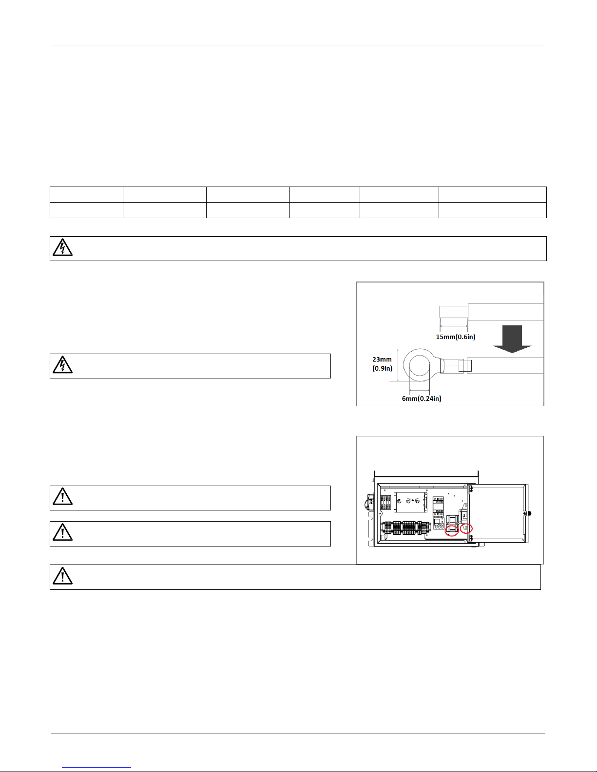
CABLES FOR BATTERY CONNECTION
CONNECTING TO BATTERY TERMINAL
BATTERY CONNECTION AND CHARGING REQUIREMENTS
There is a DC (Battery) circuit breaker in the distribution box. Before connecting the batteries, please have the
battery specifications on hand.
Notes: 1. For lead acid batteries, Flooded, Gel or AGM can be used. Please check maximum charging voltage and current
when first using this inverter.
2. If using Lithium batteries, consult with the battery manufacturer for details.
efficient operation to use the appropriate cable for battery connection.
Connecting the Batteries
Step 1. Make sure the circuit breaker is off.
Step 2. Make sure the nominal voltage for the batteries is 48VDC.
Step 3. Strip 15mm(0.6in) of insulation from each battery cable and insert it
into a ring lug.
Step 4. Connect the battery ring lugs to the battery terminals. Make sure the polarity for each connection is correct; positive to
positive and negative to negative.
RED cable to the positive terminal (+);
BLACK cable to the negative terminal (-).
breaker, make sure the connections have the correct polarity.
Step 5. Update AP registers as needed. Please refer to the remote setting (Page 28).
Rev.1 ©2018 Darfon Electronics Corp. 8 | Page
INSTALLATION MANUAL H5001 HYBRID INVERTER
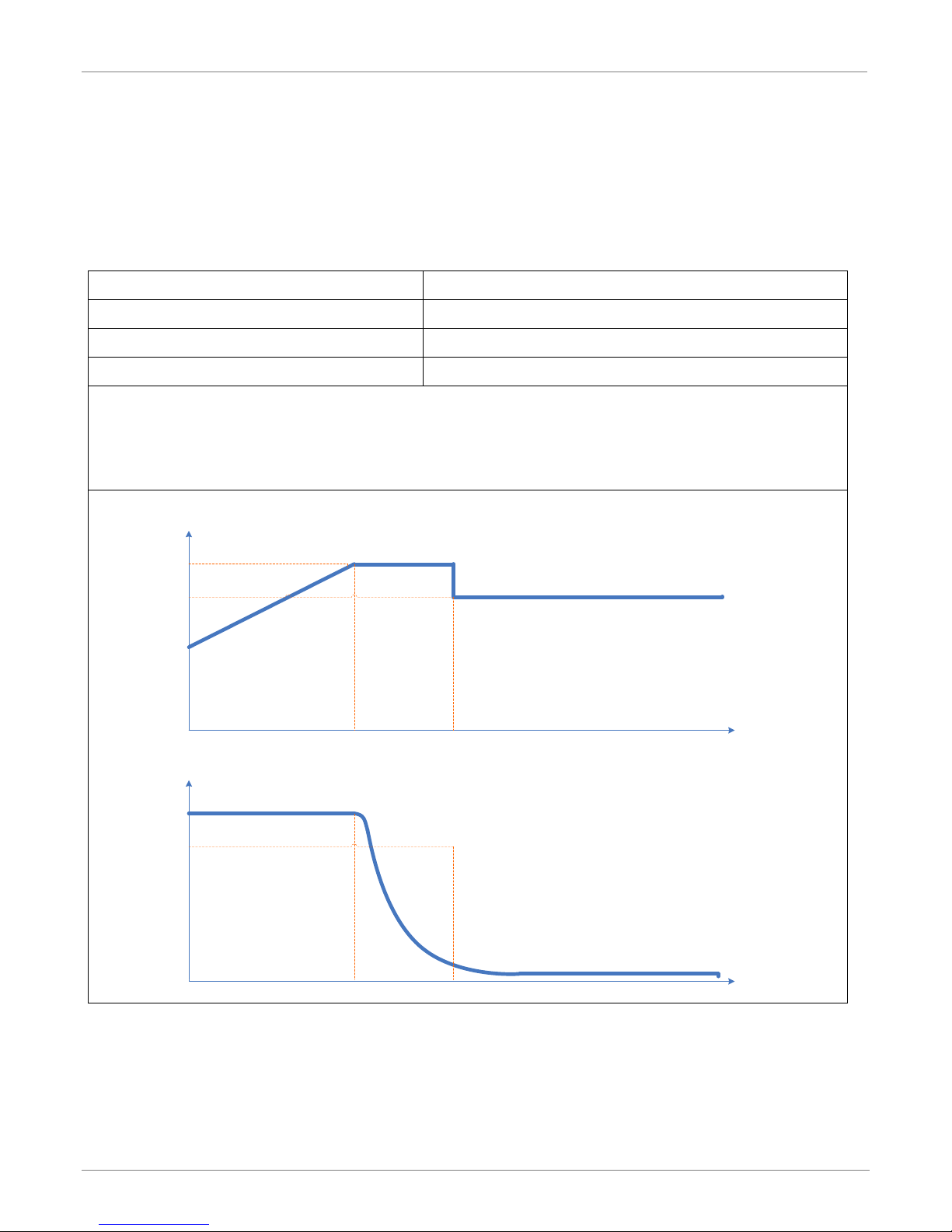
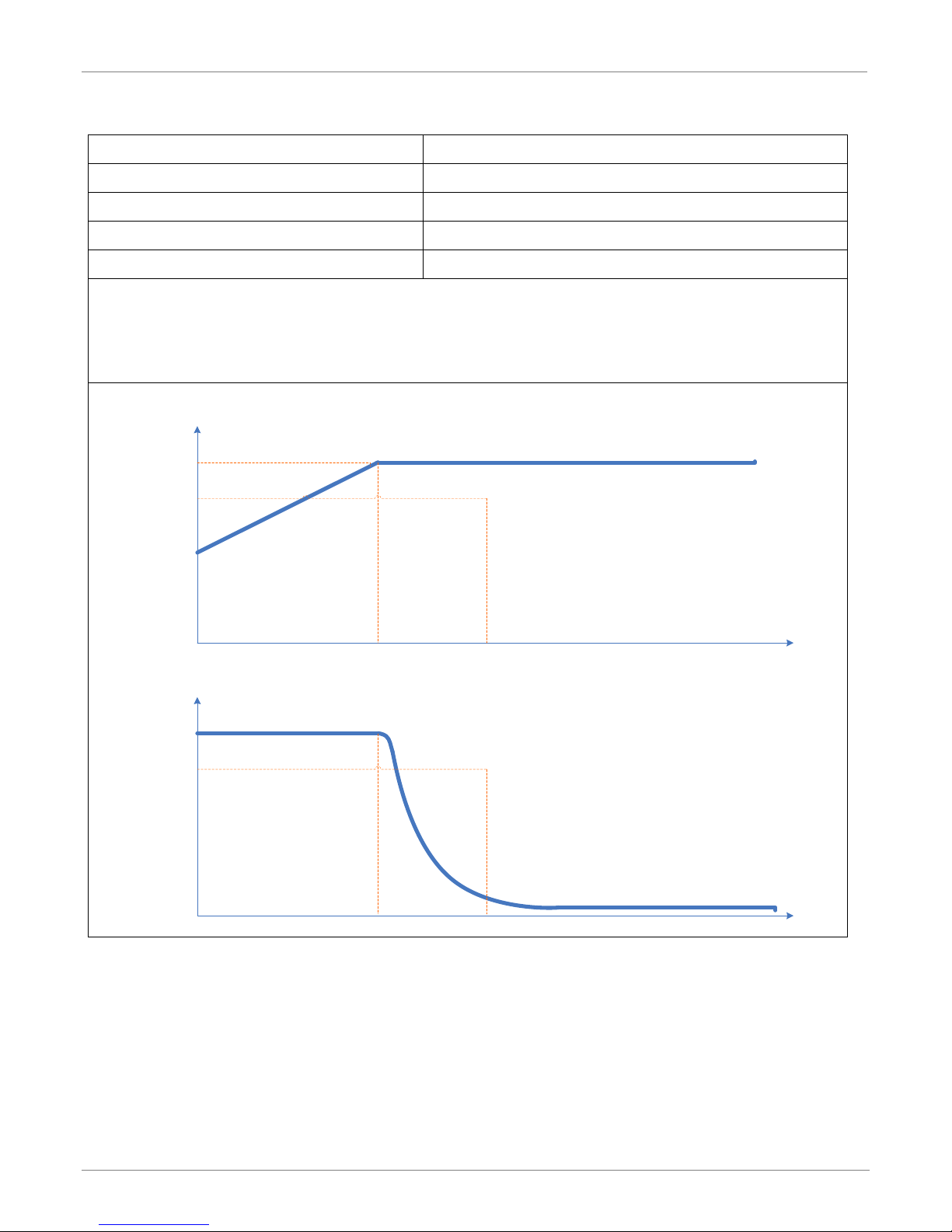
Charging Parameter
Default Value
Floating Charging Voltage
54Vdc
Charging process based on default setting.
Bulk FloatingAbsorption
time
U
time
I
Bulk Voltage
Float Voltage
Battery Charging Requirements
The default charging parameters are shown below. Use this as a reference to make sure the battery selected is
compatible with H5001 inverter. It is recommended that you use a deep cycle battery when the mode of operation
is not set as one of the two back-up modes. If you want to change battery charging parameters, please refer to the
remote setting on page 25.
1. Lead-Acid Battery Charging Characteristics(include non-conmunication batteries)
Max. Charging Current 60A
Absorption Charging Voltage 56Vdc
The three stages:
First - charging voltage increases to 56V.
Second- charging voltage will maintain at 56V until charging current is down to 2 Amp.
Third- go to floating charging at 54V.
Rev.1 ©2018 Darfon Electronics Corp. 9 | Page
INSTALLATION MANUAL H5001 HYBRID INVERTER
Charging Parameter
Default Value
Max. Charging Current
60A
Darfon Battery Charging Voltage
57.4Vdc
Charging process based on default setting.
Bulk Absorption
time
U
time
I
Bulk Voltage
Float Voltage
2. Lithium Battery Charging Characteristics
Golden Crown Battery Charging Voltage 56Vdc
Panasonic Battery Charging Voltage 52Vdc
The three stages:
First - charging voltage increases to Charging voltage.
Second- charging voltage will maintain until battery SOC is 99%.
Third- stop charging after 1 hour.
Rev.1 ©2018 Darfon Electronics Corp. 10 | Page
 Loading...