

Darfon H5000 Installation Manual

I N S T A L L A T I O N M A N U A L H 5 0 0 0 H Y B R I D I N V E R T E R
INSTALLATION MANUAL
H5000 HYBRID INVERTER
R e v . 2 © 2 0 1 7 D a r f o n E l e c t r o n i c s C o r p . 1 | P a g e

I N S T A L L A T I O N M A N U A L H 5 0 0 0 H Y B R I D I N V E R T E R
TABLE OF CONTENTS
IMPORTANT SAFETY WARNINGS ................................................................................... 3
INTRODUCTION ................................................................................................................. 4
Product Overview ..................................................................................................................... 4
MOUNTING THE INVERTER .............................................................................................. 5
Preparation ............................................................................................................................... 5
Installing the Inverter onto the Wall ....................................................................................... 5
GRID (UTILITY) CONNECT ION ........................................................................................ 7
Preparation ............................................................................................................................... 7
Connecting to the Grid/Utility .................................................................................................. 7
BATTERY CONNECTION .................................................................................................. 8
Preparation ............................................................................................................................... 8
Connecting the Batteries ......................................................................................................... 8
PV MODULE (DC) CONNECTION ..................................................................................... 9
Preparation ............................................................................................................................... 9
Connecting the PV Arrays ......................................................................................................... 9
LOAD (AC OUTPUT) CONNECTION ...............................................................................10
Preparation ..............................................................................................................................10
Connecting to the Load ...........................................................................................................10
FINAL INSTALLATION STEPS ........................................................................................11
TURNING THE SYSTEM ON ............................................................................................11
OPERATION AND DISPLAY PANEL ...............................................................................12
LCD Display Icons and Pages Introduction ............................................................................. 12
System Settings ....................................................................................................................... 13
Warning and Fault Definition .................................................................................................. 15
MODE RULE DEFINITION ................................................................................................17
AUX. CONTROL PORT ....................................................................................................18
Electric parameter ...................................................................................................................18
Function Description ...............................................................................................................18
Generator Application Schematic ...........................................................................................19
BATTERY CHARGING REQUIREMENTS .......................................................................20
HARDWARE CONNECTION: ...........................................................................................21
Connecting to the hardware ................................................................................................... 21
USE APPLICATION SOFTWARE MODIFIES PARAMETERS. ......................................23
Preparation ............................................................................................................................. 23
Connecting to the application software and modifies parameters ..................................... 23
Parameters setting tables: ..................................................................................................... 26
MAINTENANCE & CLEANING .........................................................................................28
SPECIFICATIONS .............................................................................................................29
GRID SUPPORT PARAMERTERS ..................................................................................30
5-YEAR LIMITED WARRANTY ........................................................................................32
R e v . 2 © 2 0 1 7 D a r f o n E l e c t r o n i c s C o r p . 2 | P a g e

I N S T A L L A T I O N M A N U A L H 5 0 0 0 H Y B R I D I N V E R T E R
WARNING. This indicates the risk of electric shock. The presence of high voltage levels may constitute a risk of injury or death to users
and/or installers.
CAUTION. This indicates important information where failure to comply may result in safety hazards or cause damage to this product.
CAUTION. This indicates the risk of a hot surface. The surface may reach a temperature high enough to cause serious burn injuries.
CAUTION. Before installing and using this inverter, read all instructions and cautionary markings on the inverter and all appropriate sections
of this guide.
CAUTION. Normally grounded conductors may be ungrounded and energized when a ground fault is indicated.
CAUTION. This inverter is heavy. It should be lifted by at least two persons for the safety.
WARNING. Authorized service personnel should reduce the risk of electrical shock by disconnecting AC, DC and battery power from the
inverter before attempting any maintenance or cleaning or working on any circuits connected to the inverter. Turning off controls will not
reduce this risk. Internal capacitors can remain charged for 5 minutes after disconnecting all sources of power.
WARNING. Do not disassemble this inverter yourself. It contains no user-serviceable parts. Attempt to service this inverter yourself may
cause a risk of electrical shock or fire and will void the warranty from the manufacturer.
WARNING. To avoid a risk of fire and electric shock, make sure that existing wiring is in good condition and that the wire is not undersized.
Do not operate the Inverter with damaged or substandard wiring.
CAUTION. Under high temperature environment, the cover of this inverter could be hot enough to cause skin burns if accidentally touched.
Ensure that this inverter is away from normal traffic areas.
WARNING. Use only recommended accessories from installer. Otherwise, not-qualified tools may cause a risk of fire, electric shock, or injury
to persons.
CAUTION. To reduce risk of fire hazard, do not cover or obstruct the cooling fan.
CAUTION. Do not operate the Inverter if it has received a sharp blow, been dropped, or otherwise damaged in any way. If the Inverter is
damaged, call for an RMA (Return Material Authorization).
CAUTION. This inverter is not allowed to operate in parallel. Do not parallel connect more than one unit in AC output connector. Otherwise,
it will damage this inverter.
IMPORTANT SAFETY WARNINGS
PLEASE READ ALL INSTRUCTIONS AND CAUTIONARY MARKINGS ON THE UNIT AND THIS MANUAL BEFORE USING
THE INVERTER. AND, STORE THIS USER MANUAL WHERE IT CAN BE ACCESSED EASILY.
This manual is for qualified personnel. The tasks described in this manual may be performed by qualified personnel only.
Safety Symbols
General Precautions
R e v . 2 © 2 0 1 7 D a r f o n E l e c t r o n i c s C o r p . 3 | P a g e
I N S T A L L A T I O N M A N U A L H 5 0 0 0 H Y B R I D I N V E R T E R
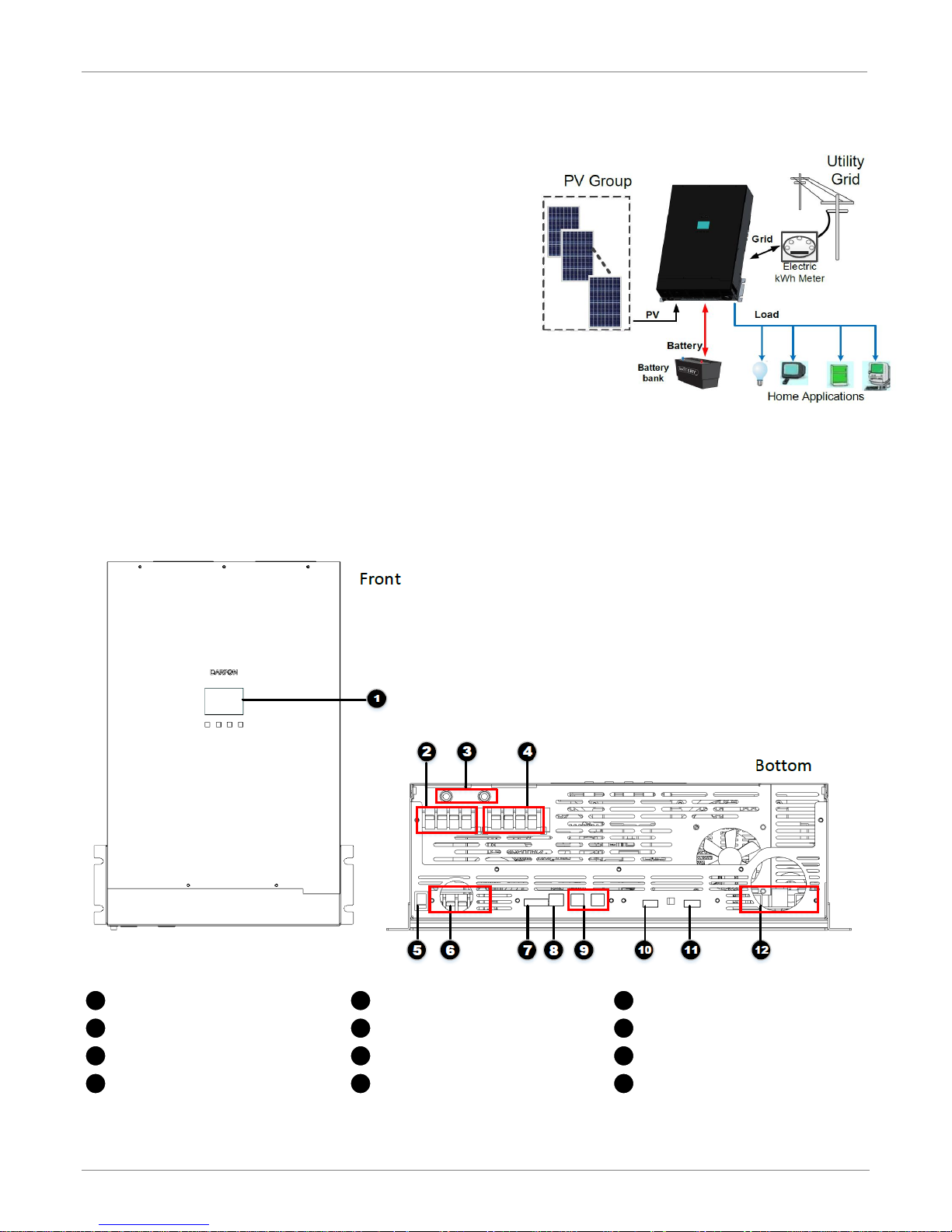
Display Panel
On/Off switch
Multi-inverter Communication Port
AC Grid Connectors
PV Connectors
RS485_MS Communication Port
Breaker for Grid Power
AUX 12V/Dry Connectors
RS485_SL Communication Port
Output Load Connectors
External Display Connectors
Battery Connectors
12 8 4
11 7 3
10 6 2 9 5
1
BASIC HYBRID PV STORAGE SYSTEM OVERVIEW
INTRODUCTION
The H5000 hybrid inverter provides power to the essential
load by utilizing power from PV panels, the utility and batteries.
When the PV panels (two string input) generates enough
power, the inverter supports the essential load, feeds back to
the grid and charges the batteries, all at the same time. When
the energy generated by the PV panels is not sufficient to
support the essential load, the inverter takes power from the
utility.
To accommodate various power situations, the H5000 is
designed to handle continuous power from PV panels,
batteries and the utility. When the MPP input voltage from the
PV panels is within the acceptable range, between 250 and
430VDC, the inverter is able to feed the grid and charge the
batteries. This inverter is only compatible with single
crystalline and polycrystalline PV panels, and any other type of PV panels cannot be used.
Note: When PV input voltage is lower than 250V, the power of the inverter will de-rate. This hybrid inverter has two PV
input.
Product Overview
R e v . 2 © 2 0 1 7 D a r f o n E l e c t r o n i c s C o r p . 4 | P a g e
I N S T A L L A T I O N M A N U A L H 5 0 0 0 H Y B R I D I N V E R T E R
CAUTION. This inverter is heavy (71lb). Be carefully while lifting and mounting the unit.
MOUNTING THE INVERTER
Preparation
Before installation, inspect the unit make sure nothing inside the package is damaged. You should have received the
following items in the package: H5000 hybrid inverter and Installation Manual.
The following considerations must be taken into account before selecting where to install.
The unit cannot be mounted on flammable construction materials.
The unit must be mounted to a solid surface.
The unit should be installed at eye level in order to easily read the LCD display at any time.
Allow 20cm (8in) of clearance to the sides and 50cm (20in) to the top and bottom of the unit for proper air circulation
to dissipate heat.
The ambient temperature must be between 0 and 50°C and relative humidity must be between 5 and 85% to ensure
optimal operation. Do not operate where the temperature and humidity are beyond the specified limits.
The unit has a Pollution Degree rating of PD2. The unit must be mounted in a protected area that is dry, free of
excessive dust and has adequate air flow.
The unit was designed with an IP20 protection rating and is for indoor applications only.
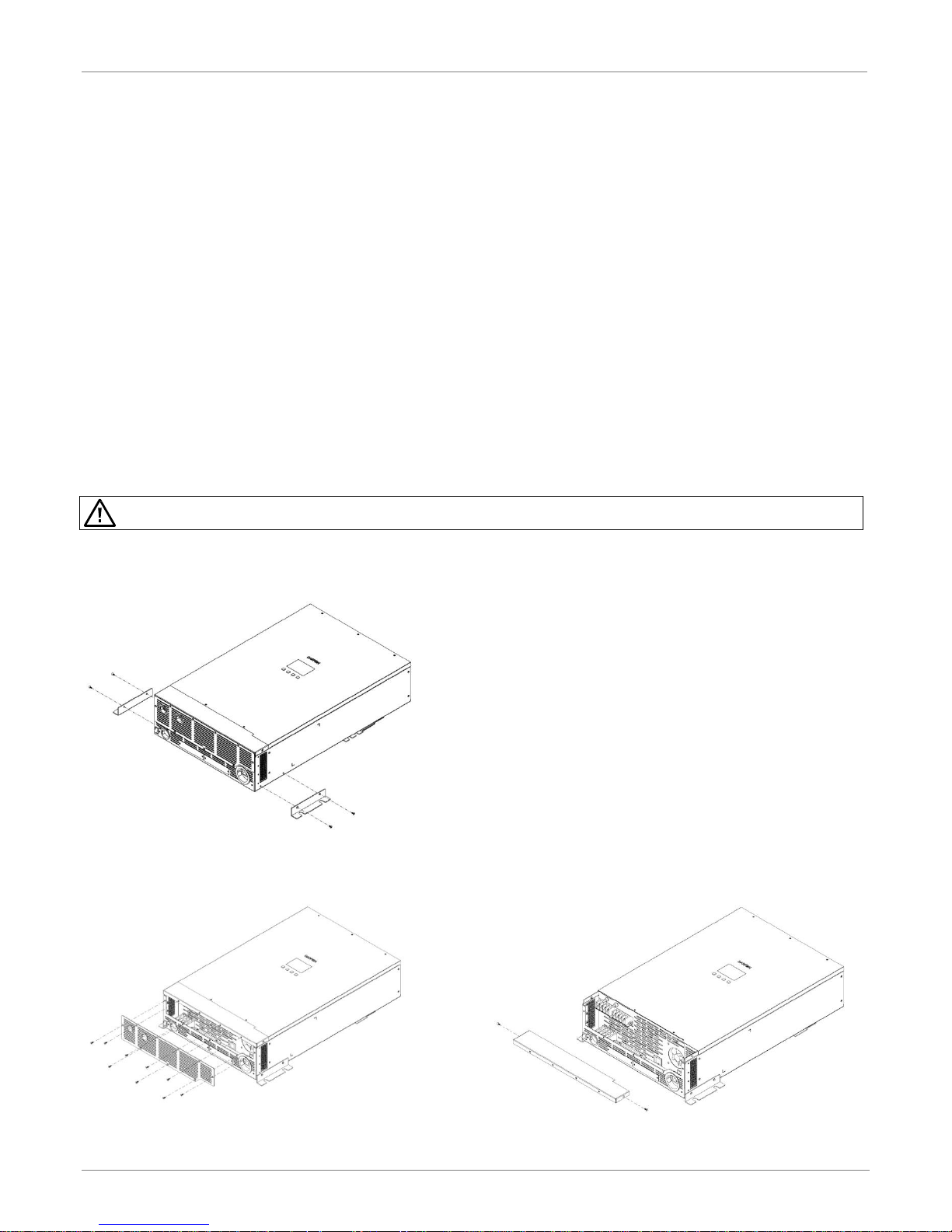
Installing the Inverter onto the Wall
Step 1. Install the bracket onto the each side of
inverter and secure it with two screws on
each side.
Step 2. Remove the eleven screws on the bottom
of the inverter and pull the bottom cover
off.
R e v . 2 © 2 0 1 7 D a r f o n E l e c t r o n i c s C o r p . 5 | P a g e
I N S T A L L A T I O N M A N U A L H 5 0 0 0 H Y B R I D I N V E R T E R
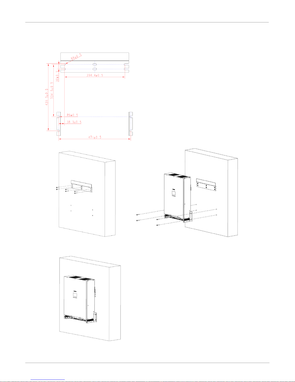
Step 3. Using the mounting bracket as a template
and install anchors as needed.
Step 4. Install the mounting bracket onto the wall.
Step 5. Hang the unit onto the mounting bracket
and secure it with two screws on each
side.
R e v . 2 © 2 0 1 7 D a r f o n E l e c t r o n i c s C o r p . 6 | P a g e
I N S T A L L A T I O N M A N U A L H 5 0 0 0 H Y B R I D I N V E R T E R
AC GRID
UTILITY
TYPE
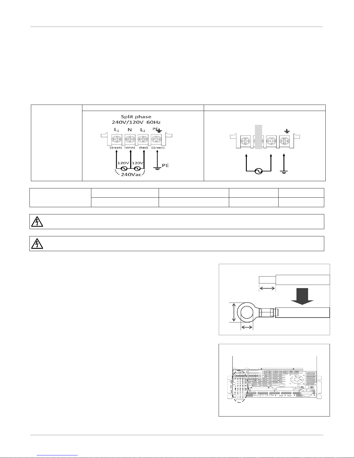
USA: 240V/120V SPLIT-PHASE SYSTEM
EURO: 230V SINGLE PHASE SYSTEM
GRID CONNECTION WIRING
REQUIREMENTS
GRID RATED POWER
NOMINAL VOLTAGE
WIRE SIZE
TORQUE
5KW
230/240 VAC
8 AWG
0.82 Nm
WARNING. To reduce the risk of injury, use the recommended wire size above. It is very important for system safety and
efficient operation to use the appropriate wire for grid (utility) connection.
WARNING. To prevent the risk of electric shock, make sure the ground wire is properly earthed before operating this unit
whether the grid is connected or not.
230Vac
L N PE
NL
Single phase
230V 50Hz
PE
(Brown) (Blue) (Green)
CONNECTIN G TO AC UTILITY TERMINAL
AC WIRE FOR GRID CONNECTION
10mm
4mm
8mm
GRID (UTILITY) CONNECT ION
Preparation
Before connecting to the utility, please install a separate AC circuit breaker between inverter and AC Grid utility. This
will ensure the inverter can be securely disconnected during maintenance and is fully protected from over current of AC
input.
Notes: 1. The separate circuit breaker is necessary for safety. Use a 240VAC/40A circuit breaker.
2. The overvoltage category of the AC input is III. It should be connected to the power distribution.
Connecting to the Grid/Utility
Step 1. Check the grid voltage and frequency with an AC
voltmeter. It should be within the operation AC voltage
range of the product’s specifications.
Step 2. Turn off the circuit breaker.
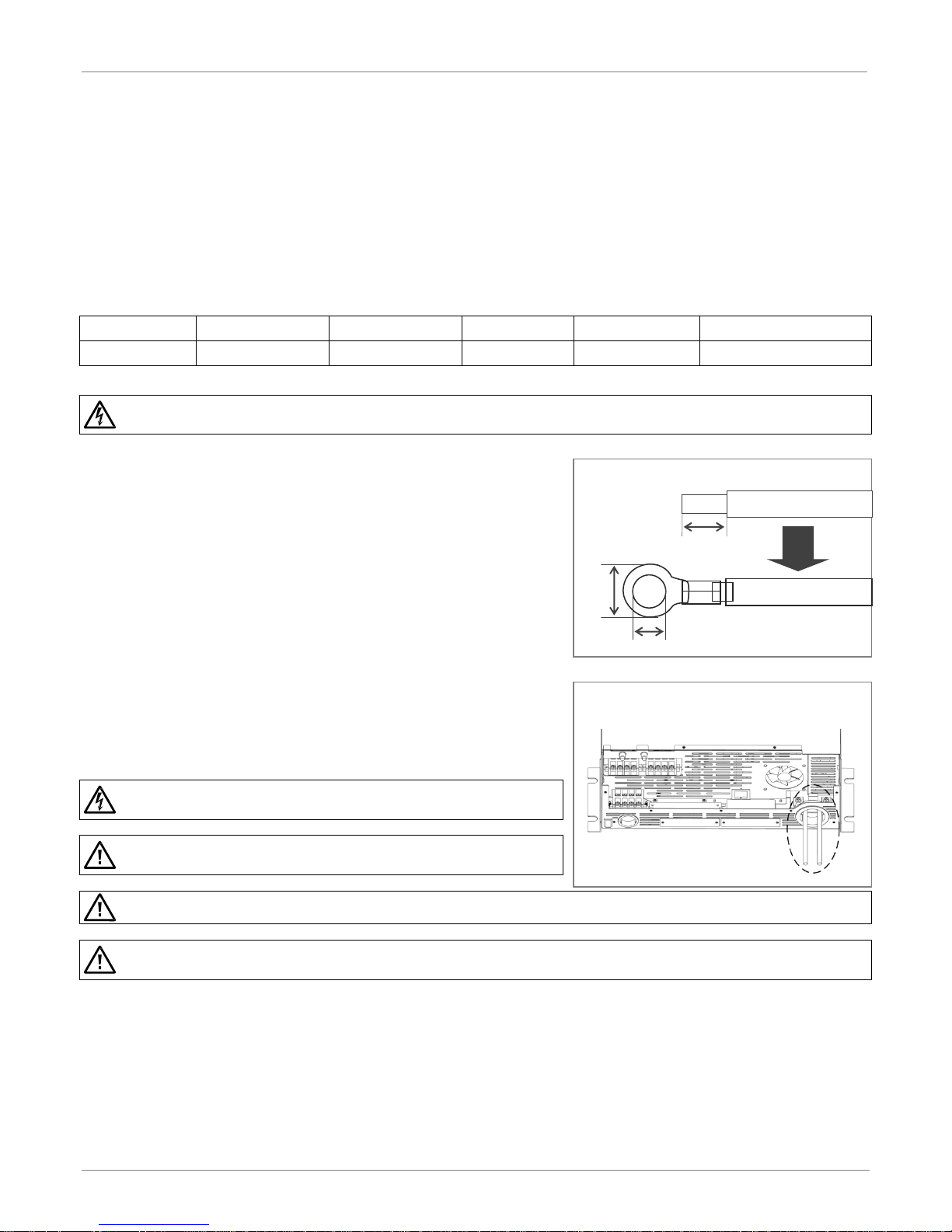
Step 3. For each AC wire, strip 8mm of isolation and then insert
the conductor into the ring lug.
Step 4. Connect the AC wires to the inverter according to the
labels indicated on the terminal block and your grid utility
type. Be sure to connect PE protective conductor (Ground)
first.
R e v . 2 © 2 0 1 7 D a r f o n E l e c t r o n i c s C o r p . 7 | P a g e
I N S T A L L A T I O N M A N U A L H 5 0 0 0 H Y B R I D I N V E R T E R
BATTERY POWER
TYPICAL AMPERAGE
BATTERY CAPACITY
CABLE LENGTH
CABLE SIZE
TORQUE VALUE
5KW
104A
200 to 600AH
< 3m (one-way)
2 AWG
2 to 3Nm (18 to 26 in-lb)
WARNING. To reduce the risk of injury, use the recommended cable size above. It is very important for system safety and
efficient operation to use the appropriate cable for battery connection.
WARNING. Shock Hazard. Installation must be performed with care due
to high battery voltage in series.
CAUTION. Do not place anything between the flat part of the inverter
terminal and the ring terminal. Otherwise, overheating may occur.
CAUTION. Do not apply anti-oxidant substance on the terminals before terminals are connected tightly.
CAUTION. Before making the final DC connection or closing DC breaker/disconnector, be sure positive (+) is connected to
positive (+) and negative (-) is connected to negative (-).
CABLES FOR BATTERY CONNECTION
23mm
6mm
15mm
CONNECTING TO BATTERY TERMINAL
BATTERY CONNECTION
Preparation
Before connecting the batteries, install a separate DC circuit breaker between the inverter and the batteries.
Notes: 1. For lead acid batteries, Flooded, Gel or AGM can be used. Please check maximum charging voltage and
current when first using this inverter.
2. If using Lithium Ferrite Phosphate batteries, consult with the battery manufacturer installer for the details.
What type of details does the installer need?
3. Use a 60VDC/160A circuit breaker.
Connecting the Batteries
Please follow below steps to implement battery connection:
Step 1. Make sure the nominal voltage for the batteries is
48VDC.
Step 2. Strip 15mm of insulation from the battery cables, and
then insert the conductors into cable ring terminals.
Step 3. Connect the external battery cable ring terminal to the
battery terminal. Following battery polarity guide
printed near the battery terminal.
RED cable to the positive terminal (+);
BLACK cable to the negative terminal (-).
R e v . 2 © 2 0 1 7 D a r f o n E l e c t r o n i c s C o r p . 8 | P a g e
I N S T A L L A T I O N M A N U A L H 5 0 0 0 H Y B R I D I N V E R T E R
TERMINAL MARK
PV INPUT POWER
TYPICAL AMPERAGE
CABLE SIZE
TORQUE
BEST VMP
VMP RANGE
PV input 1
3.25kW
13A
12 AWG
1.4~1.6 Nm
360V
250V~430V
PV input 2
3.25kW
13A
12 AWG
1.4~1.6 Nm
360V
250V~430V
WARNING. Because this inverter is non-isolated, only two types of PV modules are acceptable: single crystalline and poly
crystalline with only Class A-rated. To avoid any malfunction, do not connect any PV modules with possibility of leakage
current to the inverter. For example, non-grounded PV modules will cause leakage current to the inverter.
CAUTION. To reduce the risk of damage due to surge, Darfon recommends surge protection between the modules and the
inverter.
CAUTION. To reduce the risk of injury, use the proper cable size for PV module connection.
CAUTION. Exceeding the maximum input voltage can destroy the unit. Check the PV string voltage before wiring the
connection.
WARNING. Never touch terminals of the inverter directly. It will cause
lethal electric shock.
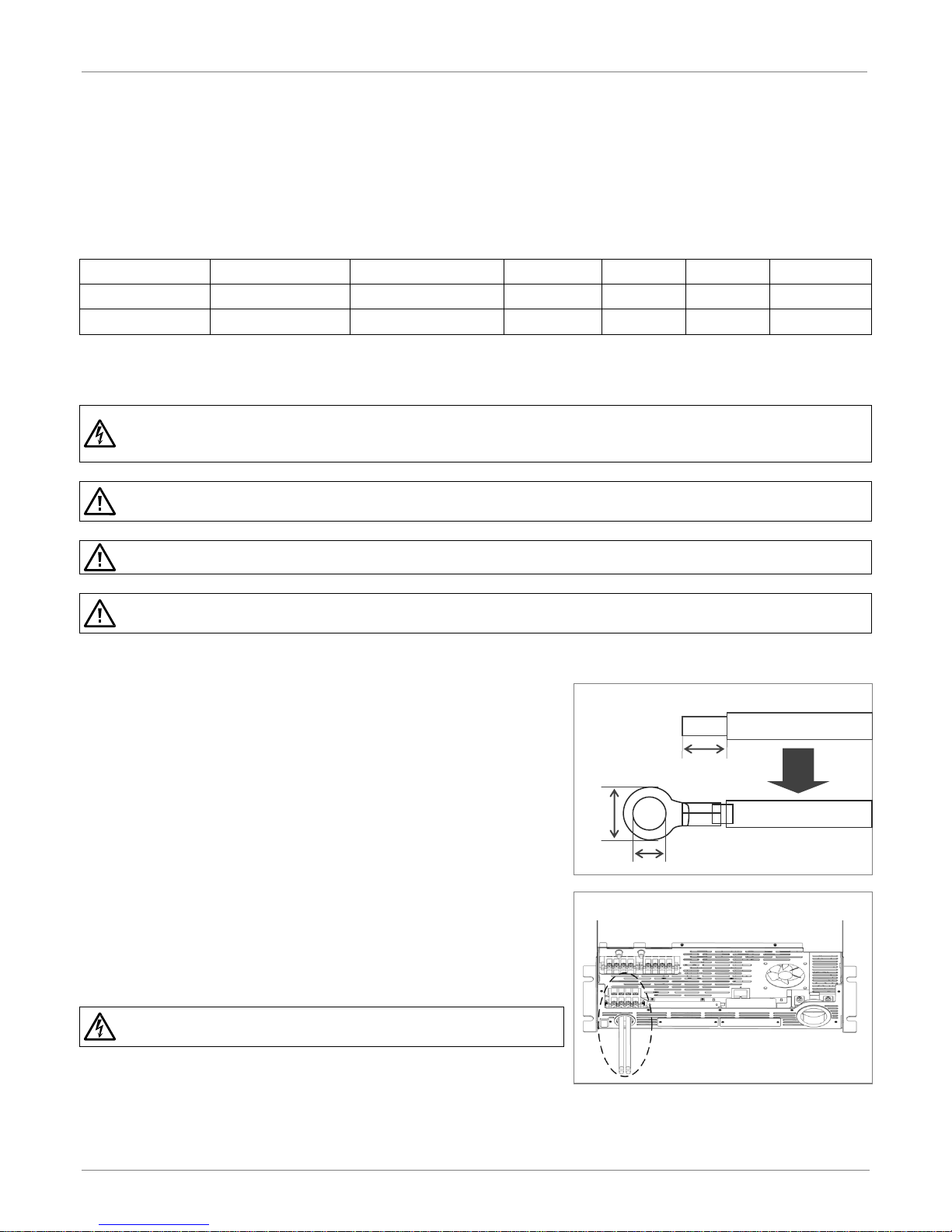
DC Cable for PV Connections
8mm
4mm
10mm
Connecting to PV module
PV MODULE (DC) CONNECTION
Preparation
Before connecting to the PV strings, install a separate DC circuit breaker between the inverter and each PV string. This
system can connect to two strings of PV modules with MPPT control.
Configure each PV input as recommended in the table below. Vmp is a PV panel’s max power point voltage. The PV
charging efficiency is maximized when the PV system’s voltage is close to Best Vmp.
Notes: 1. Use 600VDC/20A circuit breakers.
2. The overvoltage category of the PV input is II.
Connecting the PV Arrays
Step 1. For each PV input string, make sure the input voltage is
between 250VDC and 430VDC and the maximum current
is 13A.
Step 2. Turn off the circuit breaker.
Step 3. Strip 10mm of insulation from the PV cables and insert
the conductors into the cable ring terminals.
PV1+, PV1-, PV2+ and PV2-
Step 4. Check correct polarity of connection cable from PV
modules and PV input connectors. Then, connect
positive pole (+) of connection cable to positive pole (+)
of PV input connector. Connect negative pole (-) of
connection cable to negative pole (-) of PV input
connector.
R e v . 2 © 2 0 1 7 D a r f o n E l e c t r o n i c s C o r p . 9 | P a g e
I N S T A L L A T I O N M A N U A L H 5 0 0 0 H Y B R I D I N V E R T E R
AC LOAD
CONNECTION
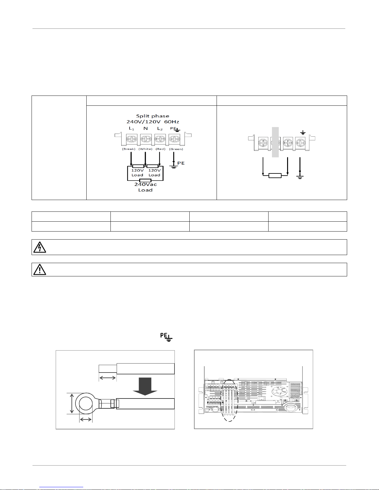
TYPE
USA: 240V/120V SPLIT-PHASE SYSTEM
EURO: 230V SINGLE PHASE SYSTEM
AC OUTPUT MAX POWER
NOMINAL VOLTAGE
WIRE SIZE
TORQUE
5KW
230/240 VAC
8 AWG
0.82 Nm
WARNING. To reduce the risk of injury, use the recommended cable size above. It is very important for system safety and
efficient operation to use the appropriate cable for AC connection.
CAUTION. Make sure the AC Load and AC Grid are properly connected. Misconnecting them will damage to this product.
230Vac
Load
NL
Single phase
230V 50Hz
PE
PE
(Brown) (Blue) (Green)
AC WIRE FOR LOAD CONNECTION
10mm
4mm
8mm
CONNECTING TO AC LOAD
LOAD (AC OUTPUT) CONNECTION
Preparation
To prevent further supply to the load via the inverter during any mode of operation, an additional disconnection device
should be placed on in the building wiring installation.
Connecting to the Load
Step 1. Use four wires AC Cables. Remove each isolation sleeve 8 mm and insert conductor into cable
ring terminal.
Step 2. Make sure your AC load type which corresponding to Grid utility type, and then connect four
wires cable (or three wires cable) according to polarities indicated on terminal block. Be sure to
connect PE protective conductor ( ) first. Refer to Fig. 12.
R e v . 2 © 2 0 1 7 D a r f o n E l e c t r o n i c s C o r p . 10 | P a g e
 Loading...