

Page 1
INSTALLATION MANUAL
CLOUD-BASED MONITORING SYSTEM
INSTALLATION MANUAL
Page 2

INSTALLATION MANUAL CLOUD- BASED MONITORING SYSTEM
TABLE OF CONTENTS
IMPORTANT SAFETY INSTRUCTIONS.................................................................................3
Safety Instructions ................................................................................................................. 3
FCC Compliance .................................................................................................................... 3
MONITORING SYSTEM...........................................................................................................4
PLC Box Overview ................................................................................................................. 4
Data Logger Overview .......................................................................................................... 5
Installing the PLC Box and Data Logger ........................................................................... 7
Registering the PV System .................................................................................................. 8
TROUBLESHOOTING ............................................................................................................ 12
Troubleshooting the PLC Box ........................................................................................... 12
Troubleshooting the Data Logger .................................................................................... 13
TECHNICAL SPECIFICATIONS ............................................................................................ 14
PLC Box ................................................................................................................................. 14
Data Logger .......................................................................................................................... 14
NOTES..................................................................................................................................... 15
Rev. 1 ©2017 Darfon Electronics Corp. 2 | Page
Page 3
INSTALLATION MANUAL CLOUD- BASED MONITORING SYSTEM
IMPORTANT SAFETY INSTRUCTIONS
PLEASE READ INSTRUCTIONS BEFORE INSTALLING AND KEEP FOR FUTURE REFERENCE.
This manual contains important instructions for the installation and maintenance of Darfon’s Monitoring System.
Before installing, please read these safety instructions carefully. Take special care to follow the warnings indicated
on the unit itself as well as the safety instructions listed below.
Safety Symbols
To reduce the risk of injury and to ensure the continued safe operation of this product, the following safety
instructions and warnings are marked in this manual.
WARNING
This indicates the risk of electric shock. The presence of high voltage levels may constitute a risk of
injury or death to users and/or installers.
CAUTION
This indicates important information where failure to comply may result in safety hazards or cause
damage to this product.
Safety Instructions
• Read all instructions and cautionary marks in the manual carefully before starting the installation. Failure to
comply with these precautions or with specific warnings elsewhere in this manual violates safety standards of
design, manufacture, and intended use of the device. The manufacturer assumes no liability for the customer’s
failure to comply with these requirements.
• Do not attempt to repair this product; it does not contain user-serviceable parts. Repairs and internal servicing
should only be performed by authorized service personnel.
• Do not tamper with or open this product. Opening this product may result in electric shock.
• Perform all electrical installations in accordance with all applicable local electrical codes and the National
Electrical Code (NEC), ANSI/NFPA 70.
• Only qualified electrical personnel should perform the electrical installation/wiring of this product.
• Switch off the circuit breakers before installation and wirings.
• For the safety of installation, remove all conductive jewelry or equipment during the installation or service of the
device parts, connector and/or wiring.
• Do not stand on a wet location while doing installation and wirings. Enclose the outer covering well before
switch on the circuit breakers.
FCC Compliance
This equipment has been tested and found to comply with the limits for a Class B digital device, pursuant to part 15
of the FCC Rules. These limits are designed to provide reasonable protection against harmful interference in a
residential installation. This equipment generates, uses and can radiate radio frequency energy and, if not installed
and used in accordance with the instructions, may cause harmful interference to radio communications. However,
there is no guarantee that interference will not occur in a particular installation. If this equipment does cause
harmful interference to radio or television reception, which can be determined by turning the equipment off and on,
you are encouraged to try to correct the interference by one or more of the following measures:
• Reorient or relocate the receiving antenna.
• Increase the separation between the equipment and the receiver.
• Connect the equipment into an outlet on a circuit different from that to which the receiver is connected.
• Consult the dealer or an experienced radio/TV technician for help.
Changes or modifications not expressly approved by the party responsible for compliance may void the user’s
authority to operate the equipment.
Rev. 1 ©2017 Darfon Electronics Corp. 3 | Page
Page 4

INSTALLATION MANUAL CLOUD- BASED MONITORING SYSTEM
FEATURE
FUNCTION
AC(PLC) Signal Input
Connects to the AC cable in the PV system.
DC Power Input
Plug the Power adapter to the DC Jack on the PLC Box.
Signal LEDs
The Signal LED will flash three times during normal startup.
Termination Resistor
If the distance between the Data Logger and PLC Box is greater than 50m, then the termination resistor
PLC signal Input
DC Power Input
Termination Resistor
Power LED
MONITORING SYSTEM
At this stage, the majority of the PV system is already installed: the PV modules and microinverters. The
following section list steps on how to install the monitoring system. Before installing, review and follow
all important safety instructions listed in the beginning of this manual.
PLC Box Overview
Signal LEDs
(Input: AC 100-240V 50-60Hz, Output: DC+12V 1A)
Power LED The Power LED will be solid when on
Represents the strength of the signal. (1 LED - weak signal, 4 LEDs - strong signal.)
Weak Signal: Strong Signal:
switch on both the Data Logger and PLC Box should be switched ON. If the distance between the Data
Logger and PLC Box is less than 50m, then the termination resistor switch on both the Data Logger and
PLC Box should be switched OFF.
Rev. 1 ©2017 Darfon Electronics Corp. 4 | Page
Page 5
INSTALLATION MANUAL CLOUD- BASED MONITORING SYSTEM
FEATURE
FUNCTION
Power Terminal Block
Plug the power adapter to the power terminal on the Data Logger.
(Input: AC 100-240V 50-60Hz, Output: DC+12V 2A)
LED Indicators
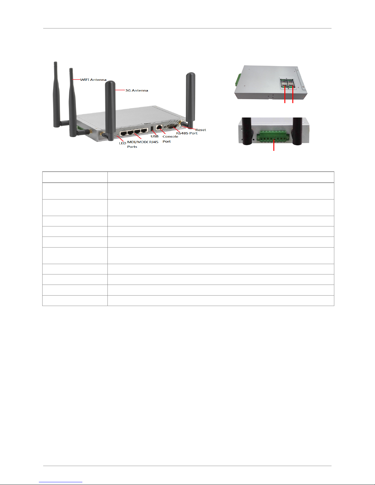
Power Source 1, Power Source 2, WLAN (WiFi), SIM A, SIM B, LAN 1, LAN 2, LAN 3,LAN 4, USB,
Serial Port, High 3G Signal, Low 3G Signal
WLAN Port
To connect to the internet (router).
LAN Port
To connect to the client device.
USB Port
To connect to a USB storage device.
Reset Button
To reset the data logger, press and hold the button for 10 seconds. The data logger will restart with
RS485 Port
To connect to the PLC Box.
WiFi Antenna
WiFi antenna is a device for sending or receiving WiFi waves.
3G Antenna
3G antenna is a device for sending or receiving 3G waves.
SIM Card Slot
Insert the SIM card to open 3G function.
Data Logger Overview
SIM A
SIM B
the default factory settings.
Power Terminal Block
Rev. 1 ©2017 Darfon Electronics Corp. 5 | Page
Page 6

INSTALLATION MANUAL CLOUD- BASED MONITORING SYSTEM
LED ICON
INDICATION
LED COLOR
DESCRIPTION
Steady ON: Wireless radio is enabled
OFF: Wireless radio is disabled
Steady ON: Ethernet connection of LAN is established
Flash: Data packets are transferred
LED Indicators
Power Source 1 Green Steady ON: Device is powered on by power source 1
Power Source 2* Green Steady ON: Device is powered on by power source 2
~
* If both power source 1 and 2 are connected, the device will choose power source 1 first. The LED of power source 2 will remain
OFF at this condition.
WLAN (WiFi) Green
SIM A Green Steady ON: SIM card A is used
SIM B Green Steady ON: SIM card B is used
LAN 1 ~ LAN 4 Green
High 3G Signal Green Steady ON: The signal strength of 3G is strong
Low 3G Signal Green Steady ON: The signal strength of 3G is weak
USB Green Steady ON: If USB device is attached
Serial Port Green Steady ON: If serial device is attached
Flash: Data packets are transferred
Rev. 1 ©2017 Darfon Electronics Corp. 6 | Page
Page 7

INSTALLATION MANUAL CLOUD- BASED MONITORING SYSTEM
CAUTION
the PLC box to the AC trunk cable or AC junction box.
Installing the PLC Box and Data Logger
Step 1: Install the PLC Box.
Connect DC power to the PLC Box through 12V/1A AC adaptor. Connect the AC wiring (PLC
Signal) from the PLC Box to the AC Trunk Cable or the AC Junction Box. The PLC Box will
need to be placed in and secured to the AC Junction Box. The wires in the AC trunk cable
are identified by color.
Disconnect the PV circuit from any grid power before installing
Step 2: Connect the Data Logger to the Router
Place the data logger near the router, then make a direct Ethernet connection. If the data
logger cannot be placed near the router, then the installer can add either a wireless access
port or a power line communication port (not supplied with the micro inverter).
Note: To mount the data logger, use the included wall-mount frame.
Step 3: Connect the Data Logger to the PLC Box
Insert the red/black wiring into the RS485 connectors, and then insert the connectors into
the Data Logger and PLC Box. (Ensure there is length of the red/black wiring is sufficient for
installation)
Note: Ensure the RS485 connectors are wired properly.
Data Logger RS485 D + PLC Box RS485 D +
Data Logger RS485 D – PLC Box RS485 D –
Note: If installing more than one PLC Box in the system, daisy-chain the PLC
Boxes together using RS485 cables. Then connect the last PLC Box in
the series to the Data Logger using the RS485 cable.
Rev. 1 ©2017 Darfon Electronics Corp. 7 | Page
Page 8

INSTALLATION MANUAL CLOUD- BASED MONITORING SYSTEM
Step 4: Connect Power
Plug in the Data Logger into the AC outlet. (Be sure the adapter is connected to the Data
Logger before it is plugged into to the outlet.)
Registering the PV System
Step 1: Before Registering
Before registering the PV system, you will need the following information:
• Data logger serial number
• Installation map with microinverter location and serial numbers
Step 2: Installer Registration
In your web browser, go to http://portal.darfonsolar.com/register/ and complete the registration
process. (If you are already registered on the Darfon Solar Portal, go to step 4.)
Step 3: Account Activation
After completing registration, a confirmation email with an activation link will be emailed to you.
Click the link to activate your account.
Rev. 1 ©2017 Darfon Electronics Corp. 8 | Page
Page 9

INSTALLATION MANUAL CLOUD- BASED MONITORING SYSTEM
Step 4: Log into the Darfon Solar Portal
Go to http://portal.darfonsolar.com. Enter your email and password, then click “Login”.
Step 5: Click “New Installation”
Select the installer and enter the data logger’s serial number.
Step 6: Enter the homeowner and site information
Be sure to select the correct time zone for the site and then click “Save & Continue”.
Rev. 1 ©2017 Darfon Electronics Corp. 9 | Page
Page 10

INSTALLATION MANUAL CLOUD- BASED MONITORING SYSTEM
Step 7: Create an Array
7.1 Enter the number of rows and columns in the array.
7.2 Drag and drop each PV modules onto the array. For each module, select/assign the
microinverter serial number, enter the module manufacturer and model, then click “Done”.
7.3 Enter in a name for the array, the tilt and the azimuth.
If you have more than one array, click “+Add More Arrays” and repeat the process.
If all the PV modules and the microinverters have been assigned, click “Next”.
Rev. 1 ©2017 Darfon Electronics Corp. 10 | Page
Page 11

INSTALLATION MANUAL CLOUD- BASED MONITORING SYSTEM
Step 8: Arrange the Arrays
Arrange the arrays to match the layout of the PV system and click the “Save” button.
Note: Uploading a background image is not required.
Step 9: Account Activation
Scroll down to the Account Activation section. Select the Send Activation Notification to
homeowner option and click “Save & Continue”.
Step 10: Completion Confirmation
The PV System registration has been completed and your screen should display the following
confirmation page.
Rev. 1 ©2017 Darfon Electronics Corp. 11 | Page
Page 12

INSTALLATION MANUAL CLOUD- BASED MONITORING SYSTEM
LED STATUS
DESCRIPTION
Power LED
No Light
No Input Power
●
Solid Green
Operating
Signal LED
No Light
No Signal from Microinverters
●●●●
One Solid Green
Weak Signal from Microinverters
●●●●
Four Solid Green
Strong Signal from Microinverters
TROUBLESHOOTING
Troubleshooting the PLC Box
If the monitoring system is not operating correctly, use the steps below to troubleshoot the problem. If
the issue cannot be resolved using these steps, please contact inverter maker’s technical services.
●
Power LED
Signal LED(x4)
RS485
Termination Resistor
DC Power Input
If the Power LED status shows no light:
• Verify the Power Adaptor is securely connected to the PLC Box
• Verify the AC source connected to Power Adaptor is turned on
If the RS485 LED status shows no light:
• Check the RS485/CAT5 connection between the PLC Box and Data Logger
• Verify the Data Logger has power
•
If the Signal Strength LEDs status shows no lights or only one solid green LED:
• Check the connections and cable distances between the PLC Box and micro inverters
• Place the PLC Box as close to the micro inverters as possible. Maximum cable distance is 164ft (50m)
If the Signal Strength LEDs status shows 3 or 4 solid green lights, but there is no communication:
• Turn the PLC Box termination resistor on
●●●●
Rev. 1 ©2017 Darfon Electronics Corp. 12 | Page
Page 13

INSTALLATION MANUAL CLOUD- BASED MONITORING SYSTEM
Troubleshooting the Data Logger
If the monitoring system is not operating correctly, use the steps below to troubleshoot the problem. If
the issue cannot be resolved using these steps, please contact inverter maker’s technical services.
3G Antennas
WiFi
Antennas
LED
Indicators
Auto MDI/MDIX RJ-45 Ports
4x FE LAN to connect local devices
USB
Port
Console
Port
Power LED did not turn on:
• Verify that the Power adapter is connected to the Data Logger and the AC outlet.
• Verify that there is power in the AC outlet.
Serial Port LED did not turn on:
• Check the RS485 connection between the Data Logger and the PLC Box.
• Verify the PLC Box has power.
WLAN LED did not turn on:
• Check the WLAN connection between the Data Logger and the router (Internet).
• Verify the router has power.
RS-485
Port
Reset
Button
Rev. 1 ©2017 Darfon Electronics Corp. 13 | Page
Page 14

INSTALLATION MANUAL CLOUD- BASED MONITORING SYSTEM
COMMUNICATION
Serial Port
DB9 RS485 for Data Logger1
Number of Devices
Up to 24 Microinverters
Transmission Distance2
Up to 164ft (50m)
MEMORY
Internal Memory
Flash ROM 16kb
MECHNICAL DATA
Operating Temperature
-10 to 50°C (14 to 122°F)
Dimensions (WxHxD)
70 x 70 x 20mm
Weight
57.1g (2oz),
Adaptor 65.3g (2.3oz)
Protection Rating
IP20 (Indoor Use Only)
Compliance
UL60950-1,
FCC Part 15 Class B
POWER
Power Consumption
7.2W (Maximum)
Power Supply Input
12VDC, 600mA
DEVICE INTERFACE
Uplink
Embedded 3G (Dual SIM), RJ45 FE
LAN
4x RJ45 FE, 11n 2T2R (WiFi)
Serial Port
DB9 RS485 (Up to 3 PLC Boxes)
Management Port
RJ12 RS232 (Console)
Storage & Log
USB 2.0 (32G Max.)
Cellular Band³ (EURO)
UMTS(WCDMA): 2100/1900/900 MHz
GSM: 1900/1800/850/900 MHz
Cellular Band (US)
UMTS(WCDMA): 2100/1900/850 MHz
Antenna (Detachable)
2x 5dBi (WiFi), 2x 3dBi (3G)
WAN FUNCTIONS
WAN
Multiple WANs, Failover/Load Balance,
Configurable Ethernet/3G
Cellular
2G/3G IPv4/IPv6, IP Pass-through
Ethernet
Dynamic IP, Static IP, PPPoE, PPTP, L2TP
IPv6
Dual Stack, 6-in-4, 6-to-4
BASIC FUNCTIONS
Ethernet
LAN IP, Subnet Mask
WiFi System
802.11n 2T2R MIMO 300Mbps (2.4GHz)
WiFi Operation
AP Router
Modes
Multi-SSID, WPS, WMM
WiFi Security
WEP, WPA,WPA2, WPA-PSK, WPA2-PSK,
VLAN
Port-based, Tag-based
NAT
ALG, Special AP, DMZ Host, Virtual Server/
Computer, PPTP/L2TP/IPSec Pass-Through
Routing
Static, Dynamic: RIP1/RIP2, OSPF, BGP
MECHNICAL DATA
Operating Temp.
-10 to 50°C (14 to 122°F)
Dimensions (WxHxD)
7.4 x 4.3 x 1.2 in (187 x 110 x 31mm)
Weight
1.5 lbs (0.67kg)
Protection Rating
IP20 (Indoor Use Only)
Compliance
UL60950-1, FCC Part 15B, Part 15C
POWER
Power Supply Input
Dual 12VDC, 2A Max.
TECHNICAL SPECIFICATIONS
PLC Box
¹ The maximum distance between the Data Logger
and PLC Box is 1312ft (400m).
² The distance from the PLC Box to the microinverter
at the farthest end of the AC branch.
³ Supported cellular band is dependent upon regional
hardware version.
3G and Wi-Fi performance will be degraded if
device's ambient temperature is above 55°C.
Data Logger
GSM: 1900/1800/850/900 MHz
802.1x
Rev. 1 ©2017 Darfon Electronics Corp. 14 | Page
Page 15

NOTES
Manufactured by:
Darfon Electronics Corp.
167 Shan-ying Road, Gueishan
Taoyuan 333, Taiwan, (R.O.C.)
Tel: +886 3 2508800
©2017 Darfon Electronics Corp. All rights reserved. All specifications are subject to change without prior notice.
Darfon and the Darfon logo are trademarks of Darfon Electronics Corp. All other trademarks are the property of the respective owners.
USA Office:
Darfon America Corp.
103A Pioneer Way
Mountain View, CA 94041
Tel: +1.650.316.6300
For more information:
www.darfonsolar.com
 Loading...