

Page 1

cPCI-SBC02 Board User manual
-
1- http://www.daqsystem.com
cPCI-SBC02
(EMB-CPU04)
User’s Manual
Windows, Windows2000, Windows NT and Windows XP are trademarks of Microsoft. We acknowledge that the
trademarks or service names of all other organizations mentioned in this document as their own property.
Information furnished by DAQ system is believed to be accurate and reliable. However, no responsibility is assumed by DAQ
system for its use, nor for any infringements of patents or other rights of third parties which may result from its use. No license is
granted by implication or otherwise under any patent or copyrights of DAQ system.
The information in this document is subject to change without notice and no part of this document may be copied or
reproduced without the prior written consent.
Copyrights 2007 DAQ system, All rights reserved.
Page 2

cPCI-SBC02 Board User manual
-
2- http://www.daqsystem.com
Contents
1 . cPCI-SBC02 Introduction
2 . cPCI-SBC02 Appearance
3 . cPCI-SBC02 Assembly (Memory, Hard Disk)
4 . Peripheral Device Control through Compact PCI
Interface(Back-Plane Connection)
5 . Expansion Port through Transition Board
6 . WINDOWS & Driver Installation
6.1 Audio Driver
6.2 LAN Driver
6.3 Touch Driver
6.4 Graphic driver
Page 3

cPCI-SBC02 Board User manual
-
3- http://www.daqsystem.com
1 . cPCI-SBC02 Introduction
It is the low cost Single Board Computer (SBC) which eq uipped a low power and low
Heat Atom processor.
Features
Intel Atom Processor Z520PT(Z510PT, Z530P)
Intel system controller hub US15WPT chipset
Intel GMA500 graphics driver (VGA, LVDS)
Single Power( +9V to +15V) operation
Compact small size 160 x 100mm
Supports industrial Temperature range (-40 - +85)
Operating Systems : Windows XP
Specifications
Form Factor 160 x 100mm
Processor Intel Atom Z520PT(512K cache, 1.33GHz, 533MHz FSB)
System Chipset Intel System Controller Hub US15WPT
Bios AMI bios
Memory 1 x 200 pin DDR2-400/533 SODIMM max up to 2GB
Extension Slot
Compact Flash slot s 44pin IDE to Compact Flash type-2 adaptor
PC card slots
NVRAMs
Display Support LVDS, VGA Dual Display
Ethernet one 10/100/1000 Mbps Ethernet port
EIDE 2mm pitch 44pin EIDE connector
Audio HD Codec audio with mono speaker AMP
Page 4

cPCI-SBC02 Board User manual
-
4- http://www.daqsystem.com
Serial I/O Two serial ports , one can be used a s touch input
Parallel Port
USB Four USB A connector, Two with 10pin header
Watch dog timer
Status LEDS Indication for Ready and operation
Power Input Single +9 to + 15V range power max current is 1.5A
Debug Connector
Operating Temperature
Rating
-40 to 50(without FAN a nd Heat-sink), -40 to +85 (with Heat-sink)
Power Consumption Max 15W
Regulator compliance
Page 5

cPCI-SBC02 Board User manual
-
5- http://www.daqsystem.com
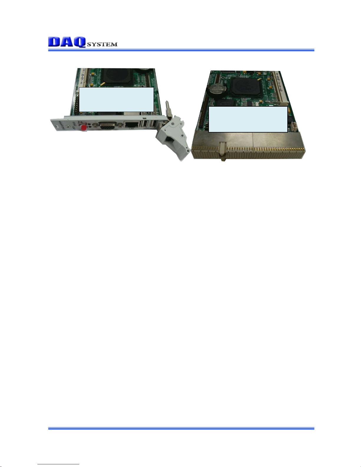
2 . cPCI-SBC02 Appearance
Table 2.1 Each Function Description
Name Description
POWER S/W Main Power switch of EMB-CPU04
SO-DIMMDDAR2
MEMORY
256M ~ 2GB memory
Intel US15WPTSCH
Intel Atom
PIC Express Slot PIC Express slot Connector.
COM1 (J17) PIN Connecter for Serial Communication
1. PIN : RX1
Page 6

cPCI-SBC02 Board User manual
-
6- http://www.daqsystem.com
2. PIN : TX1
3. PIN : Touch screen
4. PIN : Touch screen
5. PIN : GND
Speaker SPK connecter
USB 1/2 USB connecter
IDE 2.0mm 44 PIN Flash memory connecter
Two USB 10pin
Header (J10)
1.PIN , 2.PIN : +5 V
3.PIN : 1D-
4.PIN : 2D-
5.PIN : 1D+
6.PIN : 2D+
7.PIN , 8.PIN : GND
9.PIN ,10.PIN : No Connect
Ethernet one 10/100/1000 Mbps Ethernet port
Page 7
cPCI-SBC02 Board User manual
-
7- http://www.daqsystem.com
- The cPCI-SBC02 board can use to personal PC with the external Power +5V. In
front side of the cPCI-SBC02 has t he Connector O ut (VGA, Power S/W, Ethernet,
2xUSB, Power LED, Audio-Jack).
- The board connects the Back-Plane at rear side through compact PCI interface.
It can control the other devices through compact PCI interface.
Front Side
SW, VGA, Network, USB
Rear Side
Compact PCI interface
Page 8

cPCI-SBC02 Board User manual
-
8- http://www.daqsystem.com
3 . cPCI-SBC02 Assembly (Memory, Hard Disk)
1. Memory(SODIMM – SDRAM) Connection
- Memory Connection with J4 connector(256M ~ 2G)
- CF card connector board
(It is necessary to change the board if it connects 1.8” hard.)
Page 9

cPCI-SBC02 Board User manual
-
9- http://www.daqsystem.com
- Hard Disk Connection (This picture is CF card connection.)
Notice) It is necessary to change the board if it connects 1.8” hard. The picture shows differently
above picture
Page 10

cPCI-SBC02 Board User manual
-
10- http://www.daqsystem.com
4 .Peripheral Device Control through Compact PCI Interface (Back-Plane)
The cPCI-SBC02 can control the other Compact PCI products as to connect Back-
Plane like above picture.
cPCI-SBC02
Usage – Our Product cPCI-EK01
Switch
Ethernet
2xUSB
Audio
VGA
Page 11

cPCI-SBC02 Board User manual
-
11- http://www.daqsystem.com
5 . Expansion Port through Transition Board
The transition board can use through the Back-Plane. And It is possible to use the
expansion ports with connect the cPCI-SBC02. (Special Purchase)
2xUSB
RS232
2xPS2
IR
serial
LPT
FDD
Expansion rear
interface
Page 12

cPCI-SBC02 Board User manual
-
12- http://www.daqsystem.com
6 . Driver Installation
6.1 AUDIO Driver Installation
- Execute the CDROM:\Driver\audio\audio_WDM_R241\setup.exe in CD-ROM.
6.2 LAN Driver Installation
- Execute the CDROM:\Driver\Lan\AsusSetup.exe in CD-ROM.
Page 13

cPCI-SBC02 Board User manual
-
13- http://www.daqsystem.com
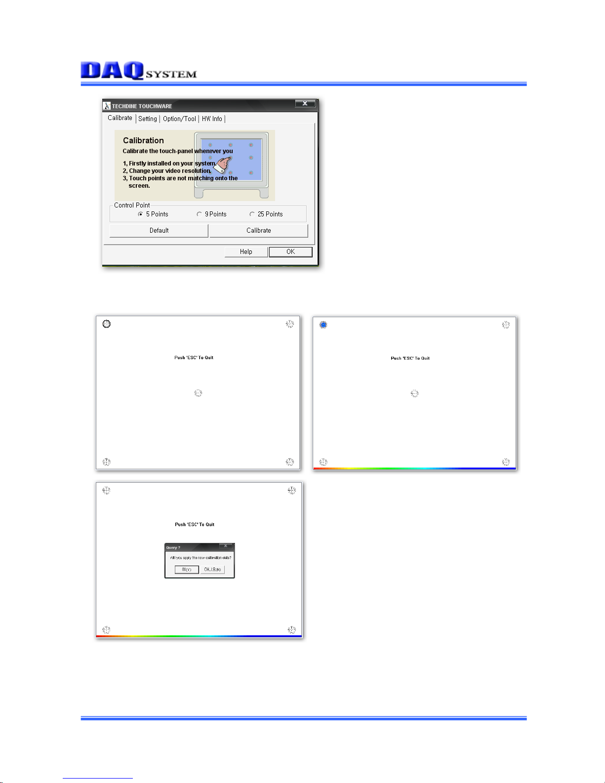
6.3 Touch Driver Installation (When 7” LCD want to use.)
- Execute the CDROM:\Driver\Touch\SetupVista32-RS232.exe in CD-ROM,
display the icon of TouchWare at the wallpaper.
- Double click the TouchW are.
- Click the “HW Info”.
- Click the “Auto Search Touch” button, check the connection port.
- After finding the port at Touch Controller, press “OK”.
- Choose the “Calibrate” button.
Page 14
cPCI-SBC02 Board User manual
-
14- http://www.daqsystem.com
- When show the below display, press the lighting point.
(You should continuously press until completed progress bar.)
- Press “Yes”, and then finished the install.
Page 15

cPCI-SBC02 Board User manual
-
15- http://www.daqsystem.com
6.4 Graphic Driver Installation (When 7” LCD want to use.)
- Execute the CDROM:\Driver\Graphic\XP\setup.exe in CD-ROM, install the
Graphic driver and re-booting.
Installation when including LCD
Setup Display
After click the right mouse at the display properties, and choose the “Graphic Property”.
MID Monitor Single Output
- It is possible with single display setting if connected to MID Monitor only.
(Single Display Output at MID Monitor)
Page 16

cPCI-SBC02 Board User manual
-
16- http://www.daqsystem.com
MID Monitor AND DeskTop Monitor Single Output
- MID Monitor and DeskTop Monitor (VGA Connecter) are all “Graphic Properties”
setting screens in connection state.
- It can be displayed to choose one of the two (MID Monitor or Desk Top Monitor) in
case of “Single Display” setting. (MID Monitor or Desk Top Monitor Single Output)
Page 17

cPCI-SBC02 Board User manual
-
17- http://www.daqsystem.com
MID Monitor AND Desk Top Monitor Multiple Output
- When “Intel(R) Dual Display Clone” is set in “Multiple Display”, it is possib le t o display
same display output at MID Monitor and DeskTop Monitor. (Same Display Output)
- It can be use the expansion monitor to make a monitor between the MID Monitor and
Desk Top Monitor, in case of setting “Expansion Desk Top”.
(Expansion Monitor Output)
Page 18

cPCI-SBC02 Board User manual
-
18- http://www.daqsystem.com
Only DeskTop Monitor Installation when not including LCD
When Installation Graphic Driver and re-booting, windows logo display shows at
DeskTop Monitor as like below picture.
After logo display di sappear, do not show nothing at DeskTop Monitor because a
graphic driver outputs a display at initial setup LCD.
At this time, press [Ctrl] + [Art] + [F1] one minute later, a display outputs at Monitor.
This setup needs a setting of once when install window.
 Loading...