

DAQSTATION DX100, DX200 User Manual

Service
Manual
DAQSTATION
DX100/DX200
Yo kogawa Electric Corporation
SM 04L01A01-01E
4th Edition

Important Notice To the User
This manual contains information for servicing the YOKOGAWA DAQSTATION DX100/
DX200. Check the serial number to confirm that this service manual corresponds to your
instrument.
Make sure not to use the wrong manual.
Before any maintenance and servicing,
Only properly trained personnel
may carry out maintenance and servicing in accordance
read all safety precautions carefully.
with and to the extent permitted by this service manual.
Do not disassemble the instrument or its parts
, unless otherwise clearly permitted by this
service manual.
Do not replace any part or assembly
, unless otherwise clearly permitted by this service
manual.
Yokogawa Electric Corporation (YOKOGAWA) does not in principle supply parts other
than those listed in the customer maintenance parts list in this service manual (mainly
modules
whole assembly and
and
assemblies
not
). Therefore if an assembly fails, the user should replace the
components within the assembly (see NOTE). If the user
attempts to repair the instrument by replacing individual components within the
assembly, YOKOGAWA assumes no responsibility for any consequences, such as
defects in instrument accuracy, functionality, or reliability, or user safety hazards.
YOKOGAWA does not offer more detailed maintenance and service information than that
contained in this service manual.
All reasonable efforts have been made to assure the accuracy of the content of this
service manual. However, there may still be errors such as clerical errors or omissions.
YOKOGAWA assumes no responsibility of any kind concerning the accuracy or contents
of this service manual, nor for the consequences of any errors.
All rights reserved. No part of this service manual may be reproduced in any form or by
any means without the express written prior permission of YOKOGAWA. The contents of
this manual are subject to change without notice.
Note
YOKOGAWA instruments have been designed in a way that the replacement of electronic parts
can be done on an assembly (module) basis by the user. YOKOGAWA instruments have also
been designed in a way that troubleshooting and replacement of any faulty assembly can be
done easily and quickly. Therefore, YOKOGAWA strongly recommends replacing the entire
assembly over replacing parts or components within the assembly. The reasons are as follows:
• The instruments use high-performance microprocessors, large scale CMOS gate arrays and
surface-mount components to provide state-of-the-art performance and functions.
• Repair of components can only be performed by specially trained and qualified maintenance
personnel with special highly-accurate tools, including costly ones.
• When taking the service life and cost of the instruments into consideration, the replacement of
assemblies offers the user the possibility to use YOKOGAWA instruments more effectively
and economically with a minimum in downtime.
• Zip is a trademark or registered trademark of Iomega Corporation in the United States
and/or other countries.
• Adobe and Acrobat are trademarks of Adobe Systems incorporated.
4th Edition : June 2010 (YK)
All Rights Reserved, Copyright © 2000, Yokogawa Electric Corporation
SM 04L01A01-01E
1
Introduction
This manual contains information for servicing the YOKOGAWA DAQSTATION DX100/
DX200.
Note
This is the third edition of the manual, dated August 2007.
This service manual is to be used by properly trained personnel only. To avoid
personal injury, do not perform any servicing unless you are qualified to do so.
Refer to the Safety Precautions prior to performing any service.
Even if servicing is carried out by qualified personnel according to this service
manual, YOKOGAWA assumes no responsibility for any result occurring from
this servicing.
Safety Precautions
WARNING
The following general safety precautions must be observed during all phases of
operation, service, and repair of this instrument. Failure to comply with these
precautions or with specific WARNINGS given elsewhere in this manual violates safety
standards of design, manufacture, and intended use of the instrument.
YOKOGAWA ELECTRIC CORPORATION assumes no liability for the customer’s failure
to comply with these requirements.
General Definitions of Safety Symbols Used on Equipment and in Manuals
High temperature. To avoid injury caused by hot surfaces, the
operator must not touch the heatsink.
Danger. Affixed to the instrument, this symbol indicates danger to
personnel or the instrument and the operator must refer to the
user's manual. The symbol is also used in the corresponding place
in user's manual.
Protective grounding terminal,to protect against electrical shock.
This symbol indicates that the terminal must be connected to
ground before operation of equipment.
Functional earth terminal. This terminal should not be used as a
“Protective earth terminal.”
WARNING
CAUTION
2
Describes precautions that should be observed to prevent serious
injury or death to the user.
Describes precautions that should be observed to prevent minor or
moderate injury, or damage to the instrument.
SM 04L01A01-01E

WARNING
Power Supply
Ensure the source voltage matches the voltage of the power supply before
turning ON the power.
Protective Grounding
The protective earth terminal must be connected to ground to prevent an electric
shock before turning ON the power.
Necessity of Protective Grounding
Never cut off the internal or external protective earth wire or disconnect the
wiring of the protective earth terminal. Doing so poses a potential shock hazard.
Fuse
To prevent a fire, make sure to use a fuse with the specified standard (current,
voltage, type). Before replacing the fuse, turn off the power and disconnect the
power source. Do not use a different fuse or short-circuit the fuse holder.
See page 3-3 or 3-4 in chapter 3.
Defect in the Protective Earth Terminal and Fuse
Do not operate the instrument when the protective earth terminal or fuse might
be defective.
Do Not Operate New Flammable Meterials
Do not operate the instrument in the presence of flammable liquids or vapors.
Operation of any electrical instrument in such an environment constitutes a
safety hazard.
Do Not Remove Any Covers
There are some components inside the instrument containing high voltages. Do
not remove any cover if the power supply is connected. The cover should be
removed by qualified personnel only.
External Connection
To ground securely, connect the protective grounding before connecting to the
measurement or control unit. Also, before touching the circuit, turn off the power
to the circuit and check that there is no voltage being generated.
SM 04L01A01-01E
3

Overview of This Manual
This manual is meant to be used by qualified personnel only. Make sure you read the
safety precautions at the beginning of this manual and the warnings and cautions
contained in any relevangt chapters prior to carrying out servicing.
This manual contains the following chapters.
1 General Information
Provides an introduction and describes safety considerations.
2 Performance Tests
Describes the tests for checking the performance of the instrument.
3 Adjustment
Describes the adjustments which can be performed by users.
4 Principles of Operation
Function block diagrams and principles of operation.
5Troubleshooting
Describes procedures for troubleshooting and how to handle the replacement of
parts.
6 Schematic Diagram
Contains the system configuration diagram.
7 Customer Maintenance Parts List
Contains exploded views and a list of replaceable parts.
Specifications are not included in this manual; for specifications, refer to IM
04L01A01-01E or IM 04L02A01-01E.
4
SM 04L01A01-01E

Contents
Important Notice To the User ...............................................................................................................1
Introduction ...........................................................................................................................................2
Safety Precautions............................................................................................................................... 2
Overview of This Manual ......................................................................................................................4
Chapter 1 Principles of Operation
1.1 Block Diagram of the DX .......................................................................................................... 1-1
1.2 Input Section ............................................................................................................................. 1-1
1.2.1 A/D Assembly ............................................................................................................... 1-1
1.2.2 Input Terminal ............................................................................................................... 1-1
1.2.3 Scanner Assembly ........................................................................................................ 1-2
1.3 Data Storage Functions ............................................................................................................ 1-2
1.4 Display Unit............................................................................................................................... 1-2
1.5 Calculation Function ................................................................................................................. 1-2
1.6 Alarm Function .......................................................................................................................... 1-2
1.7 Other Functions ........................................................................................................................ 1-2
1
2
3
4
5
Chapter 2 Testing
2.1 Acceptance Test........................................................................................................................ 2-1
2.2 Self Diagnostic Test .................................................................................................................. 2-1
2.3 Performance Test...................................................................................................................... 2-2
2.3.1 Before You Begin .......................................................................................................... 2-2
2.3.2 Measurement Accuracy Test......................................................................................... 2-3
2.3.3 Reference Junction Compensation Accuracy Test ....................................................... 2-4
Chapter 3 Replacing Parts
3.1 Replaceable Parts .................................................................................................................... 3-1
3.2 When Repair is Necessary ....................................................................................................... 3-1
3.3 Recommended Replacement Periods for Worn Parts .............................................................. 3-2
3.4 Replacing the Fuse ................................................................................................................... 3-3
3.5 Replacing the Battery ............................................................................................................... 3-4
Chapter 4 Adjustments
4.1 Before You Begin ...................................................................................................................... 4-1
4.2 AD Board Offset and Gain Adjustment ..................................................................................... 4-2
4.2.1 Manual Adjustment ....................................................................................................... 4-2
4.2.2 PC Controlled Adjustment ............................................................................................ 4-5
Chapter 5 Troubleshooting
5.1 Procedure ................................................................................................................................. 5-1
5.2 Flow Chart ................................................................................................................................ 5-1
5.3 Troubleshooting Checklist......................................................................................................... 5-2
6
7
Chapter 6 Schematic Diagram
Chapter 7 Customer Maintenance Parts List
7.1 DX100 Customer Maintenance Parts List................................................................................. 7-1
7.2 DX100 Standard Accessories ................................................................................................... 7-8
7.3 DX200 Customer Maintenance Parts List................................................................................. 7-9
7.4 DX200 Standard Accessories ................................................................................................. 7-16
SM 04L01A01-01E
5
1.1 Block diagram of the DX/1.2 Input section
Chapter 1 Principles of Operation
This chapter describes the principles of operation for the DX100 and DX200.
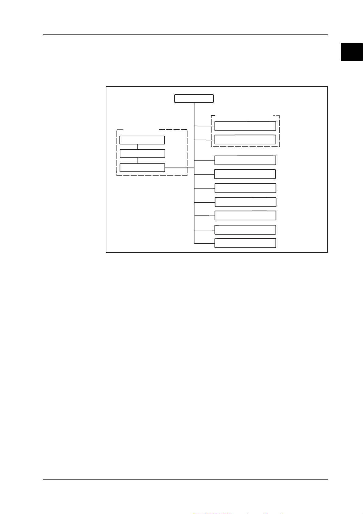
1.1 Block Diagram of the DX
CPU
Data storage functions
Input section
Input terminal
Scanner assembly
A/D assembly
External storage
Internal memory
Display unit
Calculation function
Alarm function
Communication function
Remote function
1
PRINCIPLE OF OPERATION
(optional)
1.2 Input Section
1.2.1 A/D Assembly
1.2.2 Input Terminal
Relay contact
Transmitter power supply
Figure 1 Block diagram
For datails see schematic diagram page 6-1 and 6-2.
The A/D assembly has items such as a programmable gain amp, voltage reference,
PWM modulator, current source for RTD measurements, differential amp, voltage source
for RJC, serial parallel converter, control logic, and an occurred scanner SSR control
signal.
The A/D assembly uses a sinewave oscillating type self-resonant switching power supply
(DC/DC converter), and noise filtering is achieved by signal integration.
The A/D assembly detects the frequency of the power while it is ON and the integrated
time becomes 20 ms or 16.67 ms. Therefore it carries a very high rate of noise rejection
for the power frequency (in auto mode).
In case the power frequency of the instrument and of the measured object are different,
the appropriate integrated time is manually selectable. In case of the DX106, DX112,
DX210, DX220, or DX230, the selection of 100 ms for 50/60 Hz is also available. A 16 bit
resolution is achieved regardless of the integrated time.
(optional)
(optional)
SM 04L01A01-01E
The input terminal is removable. The internal printboard is isothermal because a print
board with a metal core is being used. Therefore, stable reference junction
compensation is realized.
1-1

1.2 Input Section/1.3 Data Storage Functions/1.4 Display Unit/1.5 Calculation Function/1.6 Alarm Function/1.7 Other Functions
1.2.3 Scanner Assembly
An in-house SSR (solid state relay) is being used for the scanner. The SSR, having a
semiconductor switch, has a withstand voltage as high as 1500 V and a leakage current
of only 1 nA. For that reason, it has the following features.
1) Semi-infinite life due to the absence of mechanical contacts
2) Silent operation
3) No occurrence of thermoelectric power.
On the other hand, compared to a mechanical relay, the SSR has, the disadvantage of a
bigger ON resistance and OFF capacity. As a result, RTD measurement and noise
resistance characteristics are affected. Regarding RTD measurements, a differential
amp was inserted into the previously mentioned analog circuit without increasing the
number of parts, so that it would receive no influence from ON resistance.
For RTD measurements there is generally no insulation between channels.
1.3 Data Storage Functions
For storing data, the DX has 1.2 MB of internal memory and is equipped with a 3.5-inch
floppy disk drive (1.44 MB 2HD), a Zip drive, or an ATA flash memory card drive. The
measured data can also be saved to external storage media such as floppy disks, Zip
disks, and ATA flash memory cards.
1.4 Display Unit
The DX has a 5.5-inch (DX100) or 10.4-inch (DX200) TFT color LCD on which it displays
the measured results (240 (vertical) × 320 (horizontal) pixels for the DX100 or 480
(vertical) × 640 (horizontal) pixels for the DX200).
1.5 Calculation Function
The DX performs differential computation, linear scaling, and square roots using a
microprocessor on the CPU board.
1.6 Alarm Function
The following six alarm types can be set.
High limit (H), low limit (L), differential high limit (h), differential low limit (l), rate-ofchange on increase (R), rate-of-change on decrease (r), alarm delay upper limit alarm
(T), or alarm delay lower limit alarm (t).
1.7 Other Functions
1 Communication function:
Ethernet (standard)
RS-232/RS-422A/FOUNDATION Field bus interface added (optional).
2 Remote function:
The trigger, start/stop, time adjustment, and other functions can be controlled
remotely (optional).
3 Relay contact:
Alarm output and memory end/fail output (optional).
4Transmitter power supply:
DC24 V output for transmitter (optional).
1-2
SM 04L01A01-01E

Chapter 2 Testing
This chapter describes the following tests.
2.1 Acceptance Test/2.2 Self Dignostic Test
2.1 Acceptance test
2.2 Self Diagnostic test
2.3 Performance test
2.1 Acceptance Test
This section describes the procedure to perform the acceptance test.
1 Read the preface, to the user’s manual, “Checking the Package Contents” and verify
that you have all of the contents.
2 Make sure to understand the operating procedures as described in the user’s
manual.
3 Check each function using the user’s manual.
4 Read and implement section 2.2, “Self Diagnostic Test.”
5 Read and implement section 2.3, “Performance Test.”
2.2 Self Diagnostic Test
The DX is provided with complete self diagnostic functions to enhance reliability in
measurement and serviceability.
When you turn ON the power, the DX will automatically execute the following types of
diagnoses alternately and display the results. After these tests are completed, the DX is
ready for use.
2
PERFORMANCE TEST
1 Main ROM sum test
2 Main RAM write/read test
3 A/D and A/D ROM sum test
4 Acquisition memory test
Table 2 shows the order and results of the self diagnostic tests.
Code Message
901 ROM failure.
902 RAM failure.
910 A/D memory failure for all input channels.
911 Channel 1 A/D memory failure.
912 Channel 2 A/D memory failure.
913 Channel 3 A/D memory failure.
914 Channel 4 A/D memory failure.
921 Channel 1 A/D calibration value error.
922 Channel 2 A/D calibration value error.
923 Channel 3 A/D calibration value error.
924 Channel 4 A/D calibration value error.
930 Memory acquisition failure.
940 The Ethernet module is down.
SM 04L01A01-01E
2-1

2.3 Performance Test
2.3 Performance Test
This paragraph describes several tests to verify the operation of the DX’s performance
against published specifications.
2.3.1 Before You Begin
2.3.2 Measurement Accuracy Test
2.3.3 Reference Junction Compensation Accuracy Test
The performance tests need not be performed in any specific order.
2.3.1 Before You Begin
Testing Conditions
When carrying out the performance tests described in the following pages, make sure
the instrument is tested under the following conditions:
Ambient temperature: 23±2°C
Humidity: 55±10%RH
Power supply voltage: 90 to 132 VAC, 180 to 250 VAC
Power supply frequency: 50/60 Hz±1%
Preparation
Perform the following steps before carrying out the performance tests described in the
following pages.
1Turn ON the power supply and verify that the DX passes the self diagnostic test
without any problems.
2 Allow a warm up time of at least 30 minutes for required instruments and the unit
under test.
Instruments Required for Tests
Instrument
DC Voltage Generator
Decade Resistance Box
Thermostatic Chamber
Thermocouple
Required Specifications
Accuracy: ± 50ppm
Accuracy: ± 10ppm
± 0.01°C
Calibrated
Recommended
FLUKE 5520A
YOKOGAWA 279301
2-2
SM 04L01A01-01E
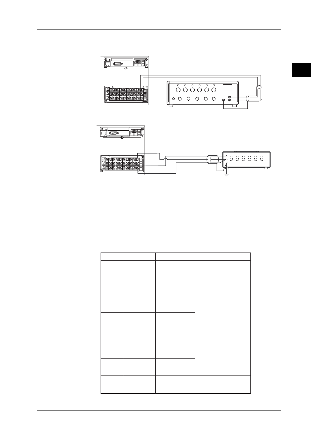
2.3.2 Measurement Accuracy Test
LN
DC voltage standard
Input terminals
(DC volt and TC inputs)
+
-
+
–
CH1
Decade resistance box
(Model 2793-01 from
Yokogawa Meters &
Instruments Corporation)
The resistance of three lead wires
must be equal.
+/A
-/B
/b
LN
Input terminals
(RTD inputs)
CH1
Connection
2.3 Performance Test
2
PERFORMANCE TEST
Procedure
1 Connect the equipment as shown in Figure 2.1
2 Carry out the preparations as described in 2.3.1
3 Apply input voltage/resistance to the DX and verify that the measured value lies
within the tolerance for each range according to the table below.
Input VoltageRange
-20 mV
20 mV
60 mV
200 mV
2 V
6 V
20 V
50 V
+20 mV
-60 mV
+60 mV
-200 mV
+200 mV
Figure 2.1 Connection diagram
Table of tolerance
Tolerance
-20.04 to -19.96
0 mV
0 mV
0 mV
-2 V
-1 V
0 V
+1 V
+2 V
-6 V
0 V
+6 V
-20 V
0 V
+20 V
-30 V
0 V
+30 V
-0.02 to +0.02
+19.96 to +20.04
-60.08 to -59.92
-0.02 to +0.02
+59.92 to +60.08
-200.4 to -199.6
-0.2 to +0.2
+199.6 to +200.4
-2.004 to -1.996
-1.003 to -0.997
-0.002 to +0.002
+0.997 to +1.003
+1.996 to +2.004
-6.008 to -5.992
-0.002 to +0.002
+5.992 to +6.008
-20.04 to -19.96
-0.02 to +0.02
+19.96 to +20.04
-30.06 to -29.94
-0.03 to +0.03
+29.94 to +30.06
Specification
±(0.1% of reading + 2 digits)
±(0.1% of reading + 3 digits)
SM 04L01A01-01E
2-3
2.3 Performance Test
Range
Pt100
Temperature
-200°C
0°C
600°C
Input Resistance
18.52 Ω
l00.00 Ω
313.71 Ω
For /N1 model
Range
Pt100
Cu10
(GE)
Cu25
Temperature
-200°C
0°C
600°C
-200°C
0°C
300°C
-200°C
0°C
300°C
Input Resistance
18.52 Ω
l00.00 Ω
313.71 Ω
1.326 Ω
9.036 Ω
20.601 Ω
3.750 Ω
25.000 Ω
56.875 Ω
Note
The error of a connected apparatus is not included in the tolerance.
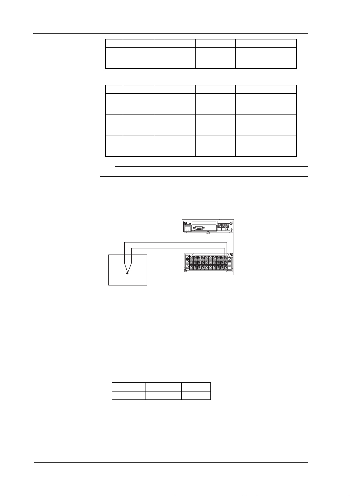
2.3.3 Reference Junction Compensation Accuracy Test
Connection
Power supply terminals
Tolerance
-200.6 to -199.4
-0.3 to +0.3
+598.8 to +601.2
Tolerance
-201.2 to -198.8
-0.6 to +0.6
+597.6 to +602.4
-201.8 to -198.2
-1.0 to +1.0
+297.8 to +302.2
-201.4 to -198.6
-0.8 to +0.8
+298.3 to +301.7
Specification
±(0.15% of reading+0.3°C)
Specification
±(0.3% of reading+0.6°C)
±(0.4% of reading+1.0°C)
±(0.3% of reading+0.8°C)
LN
Calibrated thermocouple wires
+
+
-
–
Input terminals
Thermostatic chamber (0°C)
Figure 2.2 Connection diagram
Procedure
1 Connect the instruments as shown in figure 2.2.
2 Carry out the preparations as described in 2.3.1.
3 Carry out stable ambience and secure the terminal cover to avoid the influence of
wind.
4 Set the input range for the desired thermocouple, and set the span to ±50°C.
5Verify that the measured value lies within the tolerance.
Tolerance
Temperature
0°C
Thermocouple
K,T
Tolerance
± 0.5°C *
2-4
* Detremining the actual temperature measured accuracy consists of adding the RJC
compensation accuracy and temperature range accuracy. In other words, the actual
measured value which lying within the tolerance consists of adding this value and
0˚C measured accuracy (T and K range).
Test should be done under stable ambience with the terminal cover secured to avoid
the influence of wind.
SM 04L01A01-01E

3.1 Replaceable Parts/3.2 When Repair is Necessary
Chapter 3 Replacing Parts
This chapter describes what to do when parts need to be replaced, either for preventive
maintenance or because of failure.
3.1 Replaceable Parts
3.2 When Repair is Necessary
3.3 Recommended Replacement Periods for Worn Parts
3.4 Replacing the Fuse
3.5 Replacing the Battery
3.1 Replaceable Parts
When replacement of parts is necessary, we strongly recommend replacement with an
assembly unit. YOKOGAWA instruments have been designed in a way that the
replacement of parts can be done on an assembly (module) basis by the user.
Parts supplied by YOKOGAWA are listed in the Customer Maintenance Parts List
(CMPL), in chapter 7. Smaller parts than listed in the CMPL are not supplied. The CMPL
comprises the following:
• The item number,
• The YOKOGAWA part number,
• The item quantity,
•A description.
3
REPLACING PARTS
3.2 When Repair is Necessary
When repair is necessary, clearly state the information listed below and forward it to the
nearest sales representative or service center. Addresses may found on the back cover
of this manual.
•Your address.
• Name and telephone number of the person in charge.
• Model code and suffix code of the instruments, which can be found on the name plate.
The name plate is found on the right inside of the recorder.
• Detailed explanation of the problem, including measures taken and displayed
messages.
SM 04L01A01-01E
3-1
 Loading...