

Page 1
DAQ ELECTRONICS Callisto IoG
IoG - Gateway Comm Module
Users Manual
General Information
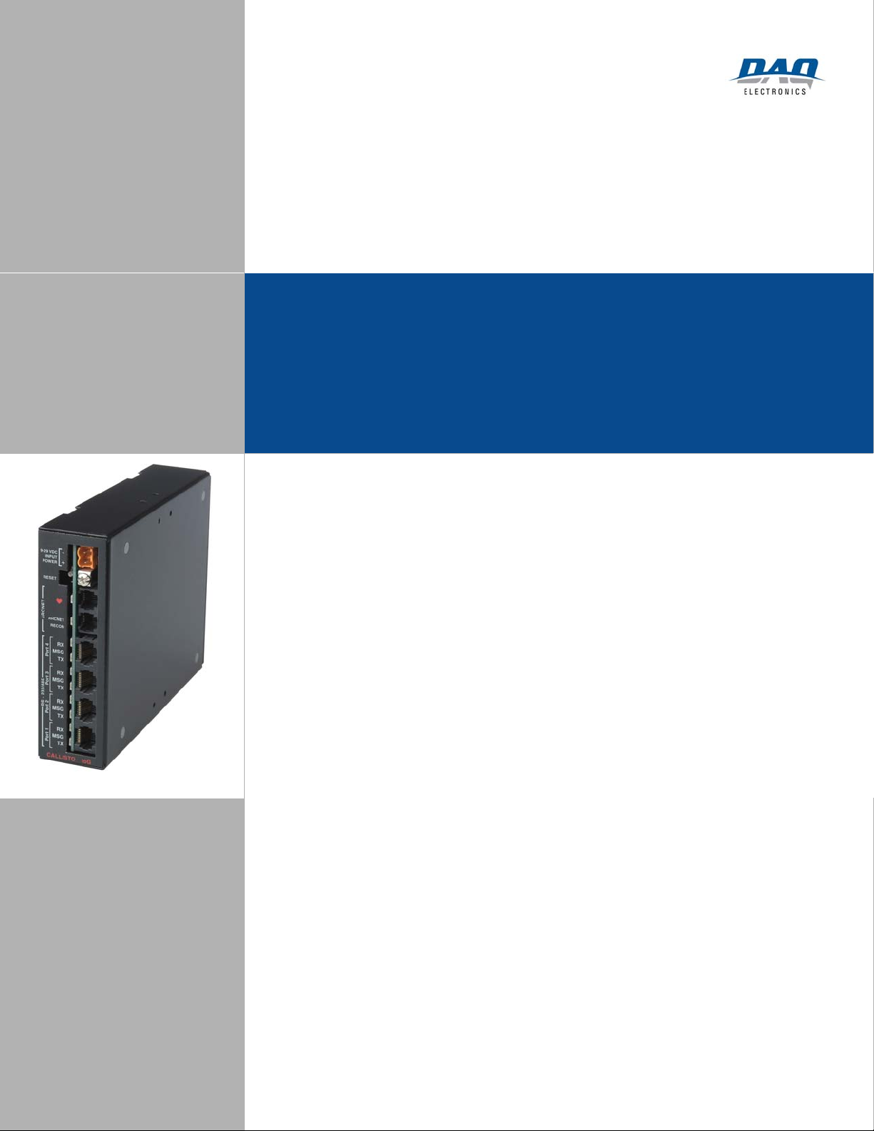
Front Panel Layout
Internal Link and DIP Switch Setup
CallistoView Configuration Software
DAQ Electronics
Piscataway Corporate Center
262B Old New Brunswick Road
Piscataway, NJ 08854-3756
Tel: 800.862.0050 / 732.981.0050
Fax: 732.981.0058
www.daq.net
- 1 -
Page 2

DAQ ELECTRONICS Callisto IoG
Section 1--General ......................................................................................... 3
1.1 Overview .................................................................................................................. 3
1.2 Packaging ................................................................................................................. 3
1.3 Mounting .................................................................................................................. 3
1.4 Unpacking ................................................................................................................ 4
Section 2--IoG Front Panel Layout ............................................................. 5
2.1 Input Power Header ............................................................................................... 5
2.2 Reset Switch ............................................................................................................. 6
2.3 Heartbeat LED ........................................................................................................ 6
2.4 Arcnet Reconfiguration LED ................................................................................. 6
2.5 Arcnet Expansion Ports .......................................................................................... 7
2.6 RS232/RS485 Communication Ports..................................................................... 7
2.6.1 Signals ............................................................................................................... 7
2.6.2 Cabling .............................................................................................................. 8
2.6.3 LEDs ................................................................................................................ 10
2.7 Ground Lug .......................................................................................................... 10
Section 3--Internal Link and DIP Switch Setup ...................................... 11
3.1 Removal of top cover ............................................................................................ 11
3.2 Watchdog Enabled/Disabled Link (LK1) ........................................................... 11
3.3 Port 1 – Port 4 RS-485 Line Biasing/Termination Link (LK2) ........................ 11
3.4 Arcnet Bus Termination Link (LK3) .................................................................. 12
3.5 Arcnet TX Enable Positive/Negative Drive Link (LK4) .................................... 13
3.6 Node Address/Port 1 Bit-Byte/Start Bit Polarity Switch (SW2) ....................... 13
3.6.1 Node Address .................................................................................................. 14
3.6.2 Communication Port 1 Byte/Bit Protocol Orientation Selector ................ 15
3.6.3 Start Bit Polarity Selector ............................................................................. 15
Section 4--CallistoView Configuration Software ..................................... 16
- 2 -
Page 3

DAQ ELECTRONICS Callisto IoG
Section 1--General
1.1 Overview
The IoG is a communications Gateway, that is an integral part of DAQ’s Callisto Series
of remote products. As such, IoG is compatible with all current Callisto IoX and Polaris
modules, and can be used stand-alone, or easily integrated into any existing Callisto
system. Combining the power and flexibility of the IoE, with the latest surface mount
technology, the module is a powerful, cost effective protocol gateway/converter. The
device supports, 4 serial ports independently selectable as RS232 or RS485, the entire
Callisto Protocol Library, and the flexibility of Callisto View configuration software.
Master station and IED protocols can be mixed and matched on a per port basis, with
individual point mappings for each communications channel. An input power range of 928 VDC allows it to be easily powered, while an Arcnet LAN interface allows for either
expansion of IoGs, or connection to an existing Callisto RTU, with a single cable.
1.2 Packaging
The IoG is mounted in a painted steel box. However, this enclosure has no NEMA
rating, is only meant for basic protection of the electronics. It is not meant for outdoor
installation of any kind, and must be placed in an appropriate auxiliary enclosure if
outdoor use is required.
1.3 Mounting
The IoG module can be mounted in any plane that is convenient for the user. two Lshaped mounting brackets and 6-32 x ¼” screws and lock washers are provided to
facilitate installation of the module to any flat surface. The L-shaped mounting brackets
are secured to the IoG module via the tapped screw holes on either side of the steel case.
- 3 -
Page 4

DAQ ELECTRONICS Callisto IoG
1.4 Unpacking
Included in your kit you should find:
(1) Callisto IoG in its enclosure
(1) 120 VAC to 12VDC Power Adapter
(2) 5 Foot Serial Communications Cable
(2) RJ45 to DB9 adapter kit
(1) 1 Foot Arcnet Cable
(2) L-shaped mounting bracket(s) with mounting hardware
(8) 6-32 x ¼” mounting screws and lockwashers
If any of these items are missing, please contact the factory at 732-981-0050.
- 4 -
Page 5
DAQ ELECTRONICS Callisto IoG
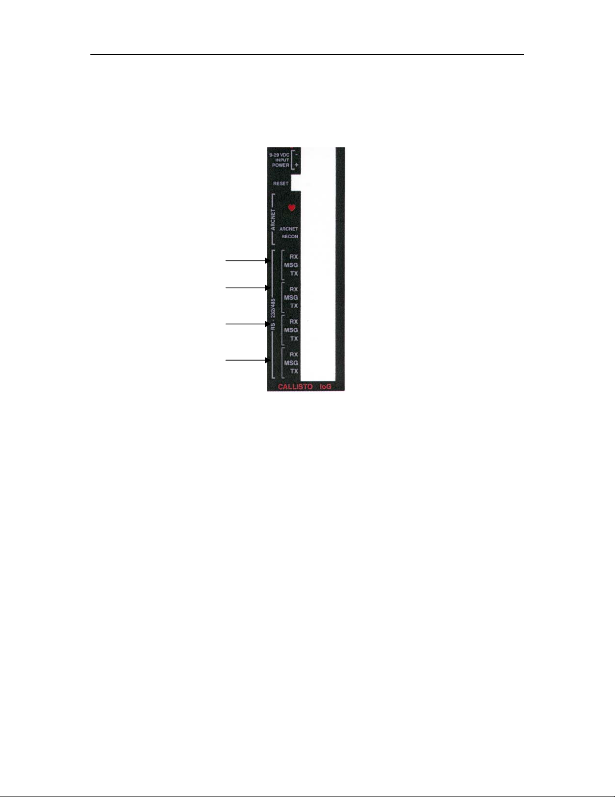
Section 2--IoG Front Panel Layout
2.1 Input Power Header
Power is provided to the IoG module through the two-pin header at the right side of the
front panel. The IoG module will operate within an input voltage range of 9-28 VDC.
The included power adapter provides 12 VDC from a 120 VAC power source.
Alternatively, any power supply capable of supplying 9-28 VDC can be utilized.
A two-position plug is provided which inserts directly into the front panel input power
header. The plug has an opening for each position, into which a wire end is inserted.
Above each opening is a captive screw which, when tightened, secures the wire end to
the plug.
If using the DAQ-supplied power adapter, insert the wire with the white stripe on the
insulation into the plug position corresponding to the (+) polarity marking for the input
power header. Tighten the screw above the opening. Insert the wire with the solid black
insulation into the remaining opening, and tighten the screw above the opening.
If using a different power source, please observe the polarity markings for the input
power, and attach the power supply wires to the plug appropriately.
- 5 -
Page 6

DAQ ELECTRONICS Callisto IoG
2.2 Reset Switch
The reset switch is located just to the left of the input power header. This switch will
restart the RTU in one of two modes of operation:
a) Functional mode – pressing and releasing the reset switch one time will reboot
the IoG, and place it into its normal operating mode. In this mode, all
configured applications are active, and the IoG carries on communication
with attached devices.
b) Default mode – pressing and releasing the reset button five times in rapid
succession reboots the IoG and places it into the default-operating mode. In
this mode, only the core IoG applications are running, and no communications
occur between the IoG and attached devices. This mode is useful for
diagnostic and troubleshooting purposes.
2.3 Heartbeat LED
The Heartbeat LED (just to the left of the reset switch) indicates proper execution of
software functions in the microprocessor, and is also used to determine the present mode
of operation.
In functional mode, the heartbeat LED will continuously toggle on for one second, then
off for one second. In default mode, the toggle rate will be approximately twice as fast,
i.e., on for one-half second, off for one-half second.
2.4 Arcnet Reconfiguration LED
The Arcnet Reconfiguration LED (just to the left of the heartbeat LED) indicates the
operational state of the Arcnet LAN, particularly in the case where two or more modules
are interfaced to form a distributed system.
An essential requirement in Arcnet LAN communication is that each connected node has
a unique Arcnet node address. If two or more nodes have the same address,
communication between nodes on the LAN will not be possible. The Arcnet
Reconfiguration LED will help determine if there is an Arcnet problem.
The Arcnet LED being on solid, or off completely indicates stability of the network. If
the LED is toggling, it implies a network problem that could be related to cabling, or
addressing. WHEN USING ONLY ONE IoG, THE ARCNET LED WILL
ALWAYS TOGGLE ON AND OFF. THIS IS PROPER OPERATION.
See Section 3.4 for the procedure for setting the node address.
- 6 -
Page 7

DAQ ELECTRONICS Callisto IoG
2.5 Arcnet Expansion Ports
The Arcnet expansion ports constitute two RJ-11 jacks, and are located on the right side
of the front panel, directly to the left of the input power header. These jacks are
physically and electrically identical, and allow quick and simple interfacing between
other IoG modules, or any other Callisto series RTU.
The Arcnet cable provided with the IoG module allows simple interconnection from IoG
to IoG. To tie together two modules plug one end of the Arcnet cable into either one of
the two RJ-11 jacks on one IoG, then plug the other end of the cable into either RJ-11
jack on the second IoG.
To add in more units, just plug one end of an additional Arcnet cable into the unused RJ11 jack of one of the existing IoG’s, and the other end into either RJ-11 jack of the new
IoG(s).
Expanding to other Callisto series RTU’s is just as easy, but it will be necessary to use
the correct type of Arcnet cable. Contact the factory for details.
Please note that Arcnet expansion, as described above, does require that each node have
a unique Arcnet address. The procedure for setting the Arcnet address in the IoG module
is described in Section 3.5.1.
Additionally, proper termination of the Arcnet bus is also necessary. This is easily
accomplished, the procedure for which is described in Section 3.3.
2.6 RS232/RS485 Communication Ports
2.6.1 Signals
The IoG module provides four RJ-45 jacks for communication between the IoG module
and connected IED’s and Master Stations.
WHEN THE MODULE IS SITTING WITH THE HEARTBEAT AND POWER AT
THE TOP, PORT 1 IS THE BOTTOM RJ-45, AND PORTS 2-4 GO UPWARDS
FROM THE BOTTOM.
Each port provides RS-232 and RS-485 signals simultaneously, therefore setting up the
port for either RS-232 or RS-485 communication merely involves selecting the
appropriate signals from the RJ-45 jack. This is easily accomplished with proper cabling.
- 7 -
Page 8

DAQ ELECTRONICS Callisto IoG
Looking at the communication ports on the front panel straight on, the communication
signals are arranged in each RJ-45 jack as shown below:
PIN SIGNAL CORESPONDING WIRE COLOR IN CABLE
1 ------------ Data Carrier Detect (DCD)-------------- Green-White
2 ------------ Receive Data (RXD)----------------------Green
3 ------------ Transmit Data (TXD)---------------------Blue-White
4 ------------ RS-485 (-) ----------------------------------Orange-White
5 ------------ Ground--------------------------------------Blue
6 ------------ RS-485 (+)----------------------------------Orange
7 ------------ Request To Send (RTS)-------------------Brown-White
8 ------------ Push To Talk (PTT)-----------------------Brown
2.6.2 Cabling
The IoG module is supplied with two 5-foot serial communications cables. These cables,
when plugged into the communications ports, will bring out all available signals. The
user now has access to RS-232 and RS-485 signals, and, depending upon what type of
cable, connector, or adapter is used, the appropriate signals can be tapped.
Note: It is possible to use either RS-232 or RS-485 communication, but not
simultaneously from the same port.
2.6.2.1 RS-485
For RS-485 communications between the IoG and an IED simply cut off the RJ-45
connector from one end of the supplied cable and connect the RS-485 (+) and RS-485 (-)
wires (Orange and Orange-White) to the IED.
- 8 -
Page 9

DAQ ELECTRONICS Callisto IoG
2.6.2.2 RS-232
Two RJ-45 to DB9 adapter kits are provided with the IoG. It is highly recommended that
the user make up a PC Configuration cable with one of these adapters, and one of the
supplied serial communication cables. This cable is necessary for downloading node
configurations from a PC to the IoG. The procedure to do this is as follows:
1) Insert the black wire from the plastic hood into the hole marked “2” on the
back end of the DB-9 connector (the back end is the end with the larger holes)
until it locks in place.
2) Insert the orange wire, into the hole marked “3” on
the back end of the DB-9 connector, until it locks in place.
3) Insert the green wire into the hole marked “5” on
the back end of the DB-9 connector, until it locks in place.
4) Individually tape off all remaining wires (to prevent shorting), and tuck into
the plastic hood, or, preferably, cut away the remaining wires.
5) Snap the DB-9 female connector into the plastic hood.
6) Plug the RJ-45 connector from one end of the supplied serial communication
cable into the RJ-45 socket on the RJ-45 to DB-9 adapter.
The second serial communication cable and RJ-45 to DB-9 adapter are provided
to facilitate the user in connecting an IED, or any other communication
requirement. For additional cabling needs, please contact the factory.
The wire colors for signals in the RJ-45 to DB-9 adapter are:
SIGNAL COLOR
Data Carrier Detect (DCD)------------ Blue
Receive Data (RXD)--------------------Orange
Transmit Data (TXD)-------------------Black
RS-485 (-) --------------------------------Red
Ground------------------------------------Green
RS-485 (+)--------------------------------Yellow
Request To Send (RTS)-----------------Brown
Push To Talk (PTT)---------------------White
- 9 -
Page 10

DAQ ELECTRONICS Callisto IoG
2.6.3 LEDs
Three LED’s are located directly above each communication port, for indication of
Transmit Data (TX), Receive Data (RX), and Good Message (MSG) states. These are
useful in determining if proper communication has been established between the IoG and
the attached device or station.
RX-Blinks on whenever data is Received on the communications port
TX-Blinks on whenever data is transmitted out of the communications port
MSG-Blinks on whenever the IoG decodes a message on the port that was
intended for it to process
2.7 Ground Lug
This screw terminal is provided for bringing an earth ground connection to the module
when required. The screw is accessible with a small Phillips head screwdriver.
- 10 -
Page 11

DAQ ELECTRONICS Callisto IoG
Section 3--Internal Link and DIP Switch Setup
3.1 Removal of top cover
In order to access the links LK1, LK2, LK3, LK4, and the DIP switch SW2; it is first
necessary to remove the top cover from the IoG case. Merely turn the thumbscrew at the
back of the case counter-clockwise until it disengages from the case, and then slide the
top cover rearwards until it is free from the case. The thumbscrew is held captive in the
top cover, so there is no danger of losing it.
3.2 Watchdog Enabled/Disabled Link (LK1)
This link is provided with a shorting jumper installed as shipped from the factory. The
shorting jumper should not be removed. This link is provided for purposes of program
debugging, and is intended for use by qualified personnel only.
3.3 Port 1 – Port 4 RS-485 Line Biasing/Termination Link (LK2)
The LK2 link is utilized when one or more communication ports have been set up for RS-
485. This link group provides 5 VDC and 0 Volts line biasing for better electrical noise
immunity, and also properly terminates the communication line by placing a 120 ohm
resistance in parallel with the high and low signal lines.
- 11 -
Page 12

DAQ ELECTRONICS Callisto IoG
This is a 16-pin (8 by 2) link, and is arranged as follows:
2 4 6 8 10 12 14 16
* * * * * * * *
* * * * * * * *
1 3 5 7 9 11 13 15
Port: [ 4 ] [ 3 ] [ 2 ] [ 1 ]
Link Pair 1-2: Port 4 RS-485 (-) Link Pair 3-4: Port 4 RS-485 (+)
Link Pair 5-6: Port 3 RS-485 (-) Link Pair 7-8: Port 3 RS-485 (+)
Link Pair 9-10: Port 2 RS-485 (-) Link Pair 11-12: Port 2 RS-485 (+)
Link Pair 13-14: Port 1 RS-485 (-) Link Pair 15-16: Port 1 RS-485 (+)
As supplied from the factory, shorting jumpers are installed across all eight link pairs. In
most cases, communication should be satisfactory between the IoG and other connected
RS-485 devices. If, however, the RS-485 devices are chained together, and one or more
of them are already terminated, communication may be impaired. If this is the case, try
removing the shorting jumpers for the RS-485 port in use. If problems still persist,
contact the factory for assistance.
3.4 Arcnet Bus Termination Link (LK3)
The Arcnet Termination Link is used to properly electrically terminate an Arcnet bus,
particularly when two or more IoG’s or a mix of IoG’s and other Callisto RTU’s are
linked together via the Arcnet ports and twisted-pair cabling.
Typically, the node at each end of an Arcnet chain is terminated with a 120 ohm
resistance, and all other nodes within the chain are left unterminated.
- 12 -
Page 13

DAQ ELECTRONICS Callisto IoG
Link LK3 is arranged as follows:
2 4
* *
* *
1 3
Link Pair 1-2: Arcnet (-) Link Pair 3-4: Arcnet (+)
If the IoG is at the end of an Arcnet chain in which the nodes are connected together with
twisted pair cabling, install shorting jumpers across link pairs 1-2 and 3-4.
If the IoG resides within the Arcnet chain (not an end node), remove the shorting jumpers
across link pairs 1-2 and 3-4.
3.5 Arcnet TX Enable Positive/Negative Drive Link (LK4)
The ArcNet TX Enable Positive/Negative Drive link is used to select either positive or
negative TX Enable signal driving of externally connected devices, such as a Fiber-Optic
converter.
As shipped from the factory, this link is set for Positive Drive, which is compatible with
all current DAQ devices.
3.6 Node Address/Port 1 Bit-Byte/Start Bit Polarity Switch (SW2)
DIP Switch SW2 serves several purposes, therefore proper setup of this switch is
essential to the proper operation of the IoG.
SW2 is an eight-position DIP switch that handles three setup parameters. These are the
node address, bit or byte protocol selection for port 1, and start bit polarity selection.
These are discussed individually in the sub-sections that follow.
- 13 -
Page 14

DAQ ELECTRONICS Callisto IoG
(
)
(
)
The eight switch positions are laid out as illustrated below:
“OFF”=Low, “ON”=High
“OFF”=Byte, “ON”=Bit
3.6.1 Node Address
The first six switch segments of the DIP switch (with respect to the SW2 circuit board
marking) are used to set the IoG node address. The node address is determined by the
mathematical sum of the bit values of all switches that are in the “ON” position. As an
example, in the illustration above, the “2”, “4”, and “8” bit value switches are in the
“ON” position, therefore the node address for the IoG would be
2 + 4 + 8 = 14 14 is the node address.
The available node address range is 1 through 63.
- 14 -
Page 15

DAQ ELECTRONICS Callisto IoG
In the case where the IoG is the only node in the system (no other nodes connected via
Arcnet communication), then the node address must be set to a value of 1.
If there are several nodes connected together via Arcnet in the system (IoG or other
Callisto series), then the IoG may be set for any convenient address, provided that the
selected address is not shared by any other node in the system. If two or more nodes share
the same address, Arcnet communication problems will result.
3.6.2 Communication Port 1 Byte/Bit Protocol Orientation Selector
The seventh switch position on the DIP switch (with respect to the “SW2” PCB marking)
allows selection, on Communication Port 1, of a bit or byte oriented protocol.
Although byte-oriented SCADA communication protocols (SES-92, DNP3, IEC
60870-5-101, etc.) are more widely used, the so-called “bit-bang” protocols (CDC, PMS91, Conitel, etc.) are still occasionally used. As such, the byte/bit selector switch permits
either type of protocol to be selected on Communication Port 1 only.
Set this switch to the “OFF” position for Byte-oriented protocols, or “ON” for Bitoriented protocols.
3.6.3 Start Bit Polarity Selector
This switch applies only when the Communication Port 1 Byte/Bit selector switch in set
for bit-oriented protocol (“ON” position).
When this switch is set to the “OFF” position, Port 1 is configured to detect low-going
start bits. Most bit-oriented protocols utilize a low-going start bit, therefore this would be
the appropriate switch position for Port 1 communication using CDC, PMS-91, Conitel,
and other “bit-bang” protocols.
Setting this switch to the “ON” position configures Port 1 to detect high-going start bits.
IRIG-B time code systems, as an example, utilize a high-going start bit.
- 15 -
Page 16

DAQ ELECTRONICS Callisto IoG
Section 4--CallistoView Configuration Software
CallistoView, DAQ Electronics configuration program for Callisto, is used for the
configuration of the IoG module. Its vast library of applications provides a high degree of
flexibility, and its user-friendly interface makes node configuration very easy.
CallistoView is available for free from DAQ’s website (www.daq.net).
Versions of CallistoView prior to version 5.1D will also require the IoG add-on software
pack, which is also available for free from DAQ’s website. Once downloaded to the PC,
simply locate the add-on pack file, then double-click on it. This will bring up a window
with some default parameters. Click on the Extract button to extract the necessary files to
the DAQTools folder.
Note: Make sure the CallistoView node editor application is closed before extracting the
add-on pack files.
After extraction of the add-on pack files, CallistoView will display an additional node
option, IoG1. Configuration is covered in the Callisto Users Manual, also available on the
website.
- 16 -
Page 17

Page 18

 Loading...