

CE8000 & CE8000LS
USER'S GUIDE
Headquarters:
955 Rue Fernand Dufour
Vanier, Quebec
Canada G1M 3B2
Tel.: (418) 681-9394
Fax: (418) 681-0799
www.daptech.com
U.S.A. subsidiary:
14502 N. Dale Mabry
Suite 227
Tampa, FL 33618-2072
Tel.: (813) 969-3271
Fax: (813) 969-3334
_MAN40-A (CMU040-A3f)
European subsidiary:
6 Place du Village des
Barbanniers
92632 Gennevilliers Cedex
France
Tel.: (33) 1-41 21 95 95
Fax: (33) 1-41 21 95 65

_MAN40-A (CMU040-A3)


_MAN40-A (CMU040-A3)

TABLE OF CONTENTS
TABLE OF CONTENTS.........................................................................................................................................................1
A WORD FROM DAP TECHNOLOGIES ...........................................................................................................................3
PRECAUTIONS ......................................................................................................................................................................7
WARRANTY STATEMENTS..............................................................................................................................................9
CE CONFORMITY CE8000..................................................................................................................................................10
CE CONFORMITY CE8000LS .............................................................................................................................................11
FCC, AS/NZA STATEMENT & COPYRIGHT POLICY................................................................................................12
MICROSOFT'S END USER LICENSE AGREEMENT......................................................................................................13
GET STARTED .....................................................................................................................................................................19
Recharging The Battery................................................................................................................................................19
Automatic Shutoff...........................................................................................................................................................2 1
Turning The Unit ON .....................................................................................................................................................21
Turning The Unit OFF Manually................................................................................................................................22
Battery Status Indicator................................................................................................................................................2 2
Touch Screen Calibration............................................................................................................................................23
Starting Display .............................................................................................................................................................23
Use of the Touch Screen................................................................................................................................................24
Caring of the Touch Screen..........................................................................................................................................2 4
Loading files and programs .........................................................................................................................................25
ADVANCED BATTERY OPTIONS...................................................................................................................................27
Battery Power Management.........................................................................................................................................2 7
Low Battery messages on Main Battery.....................................................................................................................28
Low battery messages on Backup Battery.................................................................................................................29
Replacing the main battery..........................................................................................................................................30
Recycling the battery.....................................................................................................................................................31
Power Gauge Calibration with BatMngr.exe...........................................................................................................32
BATMNGR Typical Values ...........................................................................................................................................33
USE OF THE KEYBOARD ..................................................................................................................................................35
USE OF PC CARDS..............................................................................................................................................................39
I
RDA INTERFACE ...............................................................................................................................................................41
BARCODE LASER SCANNER (CE8000LS)......................................................................................................................43
Maintenance Notice ......................................................................................................................................................44
USE OF THE CRADLE.........................................................................................................................................................45
EXTERNAL COMPACT FLASH ADAPTER...................................................................................................................47
MAINTENANCE..................................................................................................................................................................49
Main Battery maintenance...........................................................................................................................................4 9
Backup Battery Maintenance......................................................................................................................................49
Cleaning ..........................................................................................................................................................................49
Shipping The Unit..........................................................................................................................................................4 9
Carrying Strap Maintenance.......................................................................................................................................5 0
List of User Replaceable Parts.....................................................................................................................................5 0
STORAGE..............................................................................................................................................................................51
Short Term .......................................................................................................................................................................51
Long Term........................................................................................................................................................................5 1
TROUBLESHOOTING CHART ..........................................................................................................................................53
OPERATING ENVIRONMENT...........................................................................................................................................55
ADVANCED USER INFORMATION................................................................................................................................57
Where to find more information...................................................................................................................................5 7
Resetting the CE8000....................................................................................................................................................57
1
Printed in Canada
_MAN40-A (CMU040-A3)

2
_MAN40-A (CMU040-A3)

A WORD FROM DAP TECHNOLOGIES
Dear MICROFLEX CE8000(LS) Series Owner:
Thank you for purchasing a DAP Environmentally Rugged Hand-Held Computer product. It is our
pleasure to welcome you to our worldwide family of satisfied MICROFLEX owners. Manufactured
under the rigid international quality standards of ISO 9001, DAP products have earned a reputation
for quality and field reliability.
Please read this USER’S GUIDE carefully as to enjoy the full range of capabilities characteristic of
DAP’s continuing efforts to provide advanced portable computing technology. The User’s Guide
provides you with all the information you will need to operate the unit. Should you need information
about a particular application, refer to the User’s Guide provided with that application.
While we would expect you to receive consistent and reliable performance from your CE8000(LS)
Series units, we do recommend you consider protecting your investment by purchasing a DAP CARE
Maintenance Agreement. You will enjoy all the special benefits by signing up now, even though you
will not be billed until the end of your warranty period. Please contact your sales representative for
more information and for DAP CARE rates.
3
DAP TECHNOLOGIES continues to develop exciting new hardware products, as well as
enhancements to existing products, that will greatly increase the capabilities through the life of your
current system.
If, for some unexpected reason, this product does not meet our printed specifications and your dealer
is unable to make a satisfactory adjustment, please write, fax or call us at the applicable DAP address
shown below:
DAP TECHNOLOGIES
(Canada)
955 Rue Fernand Dufour
Vanier Quebec
France G1M 3B2
Tel. : (418) 681-9394
Fax : (418) 681-0799
Email : sales@daptech.com
DAP TECHNOLOGIES Corp.
(USA)
14502 N. Dale Mabry
Suite 227
Tampa, FL 33618-2072
USA
Tel. : (813) 969-3271
Fax : (813) 969-3334
Email : salestampa@daptech.com
DAP TECHNOLOGIES
(Europe)
6 Place du Village des Barbanniers
92632 Gennevilliers Cedex
France
Tel. : 33 (0) 1-41 21 95 95
Fax : 33 (0) 1-41 21 95 65
Email : salesparis@daptech.com
_MAN40-A (CMU040-A3)

4
_MAN40-A (CMU040-A3)
All rights reserved.
y
y
p
No part of this document may be copied, distributed, transmitted,
transcribed, stored in a retrieval s
any means, whether electronically or manually, including distribution on
the Web, without the ex
TECHNOLOGIES.
Every effort has been made to ensure that the information contained in this
document is accurate and up-to-date. Although DAP TECHNOLOGIES has
reviewed the document carefully, it cannot assume any responsibility for any
consequences resulting from possible errors or omissions.
DAP TECHNOLOGIES reserves the right to make changes and improvements to
this product without notice.
stem or translated in any form or b
ress written consent of DAP
5
The information in this manual refers to the CE8000 Series. This is a generic
name indicating that the information is valid for the CE8000 and CE8000LS
Consequently, except where otherwise indicated, it covers information for the
CE8000 and CE8000LS
This user’s guide applies to:
CE8000 Series unit running Windows CE 3.00 Pack D or earlier and
manufactured after April 1st, 2003
Please report your comments and problems to us to make this
document more accurate (support@qbc.daptech.com).
See section Advance User Information to find where to download and
access more information about this product.
_MAN40-A (CMU040-A3)

6
_MAN40-A (CMU040-A3)
PRECAUTIONS
l
t
¾ Refer to this manual when inserting or removing batteries, cables or externa
peripherals.
¾ Operate and store your Microflex within the limits of temperature specified in
this manual.
¾ Do not use any pointed objects on the keyboard, door or mechanisms. Doing
so can damage the unit
¾ Use the stylus supplied by DAP TECHNOLOGIES with the unit since it has
been designed with a non-abrasive material that cannot scratch or deteriorate
the touch membrane.
¾ Never expose battery to extreme heat or dispose of in a fire
¾ Any attempts to open the case of a CE8000 Series unit will void the warranty
7
¾ The LEMO communication connector for the CE8000 Series unit has
proprietary pin-out distribution. Any attempt to connect cables other than the
ones supplied or recommended by DAP TECHNOLOGIES could result in
damage to the CE8000 or CE8000LS.
¾ If you need to use a cable other than the ones supplied or recommended by
DAP, we suggest you contact DAP TECHNOLOGIES Technical Support
Department beforehand.
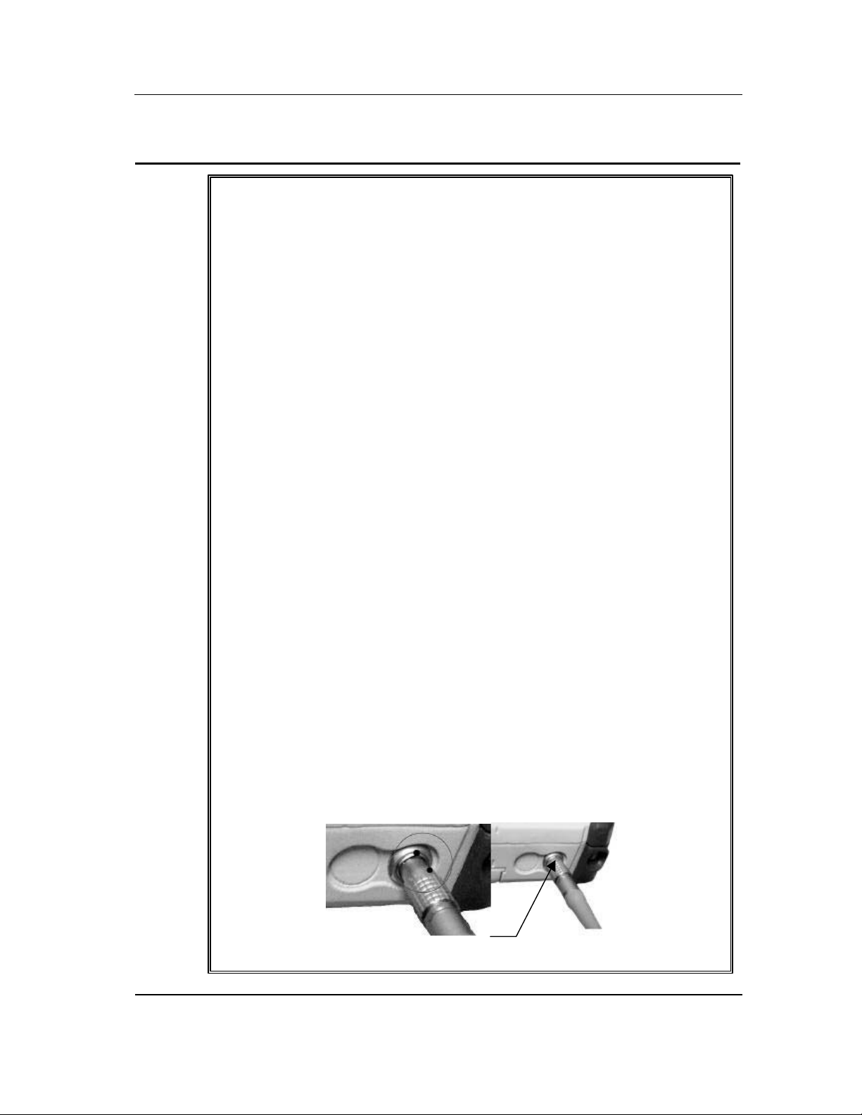
¾ When removing the Lemo cable, DO NOT TWIST the cable connector.
Using the gray metal connector of the Lemo cable, pull back on the cable to
remove it from the connector.
¾ To insert the Lemo cable, align both red dots found on the cable and on the
CE8000 connector than, insert the cable into the connector of the unit.
Align red dots and inser
the connector in place
_MAN40-A (CMU040-A3)

8
_MAN40-A (CMU040-A3)

WARRANTY STATEMENTS
DAP TECHNOLOGIES makes no representation or warranties with respect to the contents hereof and specifically
disclaims any implied warranties of merchantability or fitness for any particular purpose.
The information in this manual is subject to change. DAP TECHNOLOGIES reserves the right to update and
modify the MICROFLEX, its accessories and manuals without notice.
No part of this manual may be copied, distributed, transmitted, transcribed, stored in a retrieval system, or
translated in any form or by any means, whether electronically or manually, without the express written consent of
DAP TECHNOLOGIES.
MICROFLEX AND ACCESSORIES LIMITED WARRANTY
As manufacturer, DAP TECHNOLOGIES will replace or repair, at its discretion, any products that prove to be
defective, in either material or workmanship, for a period of one year following the purchase date of the
MICROFLEX hand-held computer and for a period of nineteen (90) days following the purchase date of
MICROFLEX accessories sold by DAP TECHNOLOGIES. The warranty only cover the material and workmanships
This warranty does not cover damages caused by misuse, abuse, neglect, or occurred during shipping or storage;
the warranty does not also cover any modification or servicing by any one other than a DAP TECHNOLOGIES
Authorized Service Center.
DAP TECHNOLOGIES cannot be held responsible for any damage caused by the misuse of the MICROFLEX or
by any other software or hardware added to the MICROFLEX.
The operating system, MS-DOS, Windows CE and all other software sold or supplied by DAP TECHNOLOGIES
are provided as is, without any warranty, either expressed or implied.
In no event shall DAP TECHNOLOGIES be liable for any direct, indirect damages or damages of any kind,
including but not limited to damages on account of the loss of present or prospective profits arising out of or in
connection with the use or failure of performance of the product. No claim may be made against DAP
TECHNOLOGIES under this head, whether arising from contractual, extra-contractual or statutory liability.
9
The warranty allowed hereby excludes all other legal warranty related to the quality of the product or its capacities
to fulfill specific purposes, including all warranties granted by the United Nations Convention on Contracts for
the International Sales of Goods, the application of such Convention being expressly excluded
RETURN MERCHANDISE AUTHORIZATION (RMA)
SERVICING
In order to have your product serviced, you must first obtain a Return Material Authorization (RMA) from DAP
TECHNOLOGIES. You may then return your MICROFLEX, correctly enclosed in its original packaging if possible,
to your Value Added Reseller (VAR), an Authorized Service Center, or directly to DAP TECHNOLOGIES. Service
under the conditions of this warranty requires prepaid shipment from your facility to a Service Center.
The MICROFLEX and its accessories have no user serviceable parts.
To obtain a RMA you can make your request by phone or use our on-line form at:
http://www.daptech.com/rma
EXTENDED WARRANTY ON DAP MANUFACTURED PRODUCTS
The original purchaser may, at any time during the initial warranty period, extend the warranty through
purchase of a DAP CARE Service Contract. For more information, contact DAP TECHNOLOGIES
_MAN40-A (CMU040-A3)

10
CE CONFORMITY CE8000
The CE8000 meets the 89/336/EEC directive intent for Electromagnetic Compatibility
Compliance when used with DAP’s accessories and cables.
The compliance was demonstrated to the following specifications as listed in the official
Journal of the European Communities:
Emissions:
EN 55022 Radiated & conducted, CLASS B
CISPR 22:1997-11 For CLASS B
EN 61000-6-2:2001, Electromagnetic Immunity:
IEC 61000-4-2:1995 Electrostatic discharge (ESD)
IEC 61000-4-3:1996 Radio Frequency Electromagnetic Field Amplitude
Modulated
IEC 61000-4-4:1995 Fast Transients
IEC 61000-4-5:1995 Surges Line-to-earth, Line-to-Line
IEC 61000-4-6:1996 Radio Frequency Continuous Conducted
IEC 61000-4-11:1994 Voltage Interruption
_MAN40-A (CMU040-A3)

CE CONFORMITY CE8000LS
The CE8000LS meets the 89/336/EEC directive intent for Electromagnetic Compatibility
Compliance when used with DAP’s accessories.
The compliance was demonstrated to the following specifications as listed in the official
Journal of the European Communities:
Emissions:
EN 55022 Radiated & conducted, CLASS B
CISPR 22:1997-11 For CLASS B
EN 61000-6-2:2001, Electromagnetic Immunity:
IEC 61000-4-2:1995 Electrostatic discharge (ESD)
IEC 61000-4-3:1996 Radio Frequency Electromagnetic Field Amplitude
Modulated
IEC 61000-4-4:1995 Fast Transients
IEC 61000-4-5:1995 Surges Line-to-earth, Line-to-Line
IEC 61000-4-6:1996 Radio Frequency Continuous Conducted
IEC 61000-4-11:1994 Voltage Interruption
11
Safety of Laser Product
IEC 60825-1:1993+ A1:1997 + A2:2001 Class 2, Laser Safety Approvals
US Federal (FDA) Regulation
21 CFR Chapter I, Subpart J, Part 1040.10
Performance Standards for Light Emitting Products
(Class II Laser Product)
_MAN40-A (CMU040-A3)

12
FCC, AS/NZA STATEMENT
& COPYRIGHT POLICY
FEDERAL COMMUNICATIONS COMMISSION RADIO FREQUENCY
INTERFERENCE STATEMENT
This equipment has been tested and found to comply with the limits for a Class B digital device,
pursuant to Part 15 of the FCC Rules. These limits are designed to provide reasonable protection
against harmful interference when the equipment is operated in a residential environment. This
equipment generates, uses, and can radiate radio frequency energy and, if not installed and used in
accordance with the instruction manual, may cause harmful interference to radio communications.
However, there is no guarantee that interference will not occur in a particular installation.
Changes or modifications not expressly approved by the party responsible for compliance could void the
user’s authority to operate the equipment.
AS/NZA 3548: 1995 for Class B
Powerline Conducted Emission Para. No. 5; Radiated Emission Para. No. 6
COPYRIGHT POLICY
Any software described in this document is furnished under a license agreement or non-disclosure
agreement. It is against the law to copy any software supplied by DAP TECHNOLOGIES onto
magnetic tape, disk, or any other medium for any purpose other than the purchaser’s personal use.
READ CAREFULLY THE «MICROSOFT'S END USER LICENSE AGREEMENT» on the
next page
MICROFLEX is a registered trademark of DAP TECHNOLOGIES. MICROSOFT, MS_DOS and
Windows CE are registered trademarks of Microsoft Corporation. PCMCIA and PC Card are
registered trademarks of PCMCIA Corporation. IrDA is a registered trademark of Infrared Data
Association
.
_MAN40-A (CMU040-A3)

13
MICROSOFT'S END USER LICENSE
AGREEMENT
You have acquired an item (“DEVICE”) that includes software licensed by DAP Technologies from Microsoft Licensing Inc.
or its affiliates (“MS”). Those installed software products of MS origin, as well as associated media, printed materials, and
“online” or electronic documentation (“SOFTWARE”) are protected by copyright laws and international copyright treaties, as
well as other intellectual property laws and treaties. The SOFTWARE is licensed, not sold.
IF YOU DO NOT AGREE TO THIS END USER LICENSE AGREEMENT (“EULA”), DO NOT USE THE DEVICE OR
COPY THE SOFTWARE. INSTEAD, PROMPTLY CONTACT DAP TECHNOLOGIES FOR INSTRUCTIONS ON
RETURN OF THE UNUSED DEVICE(S) FOR A REFUND. ANY USE OF THE SOFTWARE, INCLUDING BUT NOT
LIMITED TO USE ON THE DEVICE, WILL CONSTITUTE YOUR AGREEMENT TO THIS EULA (OR
RATIFICATION OF ANY PREVIOUS CONSENT).
GRANT OF LICENSE. The SOFTWARE is licensed, not sold. This EULA grants you the following rights to the
SOFTWARE:
¾ You may use the SOFTWARE only on the DEVICE.
¾ NOT FAULT TOLERANT. THE SOFTWARE IS NOT FAULTED TOLERANT. DAP TECHNOLOGIES HAS
INDEPENDENTLY DETERMINED HOW TO USE THE SOFTWARE IN THE DEVICE, AND MS HAS RELIED
UPON DAP TECHNOLOGIES TO CONDUCT SUFFICIENT TESTING TO DETERMINE THAT THE
SOFTWARE IS SUITABLE FOR SUCH USE.
¾ NO WARRANTIES FOR THE SOFTWARE. THE SOFTWARE is provided “AS IS” and with all faults. THE
ENTIRE RISK AS TO SATISFACTORY QUALITY, PERFORMANCE, ACCURACY, AND EFFORT
(INCLUDING LACK OF NEGLIGENCE) IS WITH YOU. ALSO, THERE IS NO WARRANTY AGAINST
INTERFERENCE WITH YOUR ENJOYMENT OF THE SOFTWARE OR AGAINST INFRINGEMENT. IF YOU
HAVE RECEIVED ANY WARRANTIES REGARDING THE DEVICE OR THE SOFTWARE, THOSE
WARRANTIES DO NOT ORIGINATE FROM, AND ARE NOT BINDING ON, MS.
¾ Note on Java Support. The SOFTWARE may contain support for programs written in Java. Java technology is not
fault tolerant and is not designed, manufactured, or intended for use or resale as online control equipment in hazardous
environments requiring fail-safe performance, such as in the operation of nuclear facilities, aircraft navigation or
communication systems, air traffic control, direct life support machines, or weapons systems, in which the failure of Java
technology could lead directly to death, personal injury, or severe physical or environmental damage. Sun Microsystems,
Inc. has contractually obligated MS to make this disclaimer.
¾ No Liability for Certain Damages. EXCEPT AS PROHIBITED BY LAW, MS SHALL HAVE NO LIABILITY FOR
ANY INDIRECT, SPECIAL, CONSEQUENTIAL OR INCIDENTAL DAMAGES ARISING FROM OR IN
CONNECTION WITH THE USE OR PERFORMANCE OF THE SOFTWARE. THIS LIMITATION SHALL
APPLY EVEN IF ANY REMEDY FAILS OF ITS ESSENTIAL PURPOSE. IN NO EVENT SHALL MS BE LIABLE
FOR ANY AMOUNT IN EXCESS OF U.S. TWO HUNDRED FIFTY DOLLARS (U.S.$250.00).
¾ Limitations on Reverse Engineering, Decompilation, and Disassembly. You may not reverse engineer, decompile,
or disassemble the SOFTWARE, except and only to the extent that applicable law notwithstanding this limitation
expressly permits such activity.
¾ SOFTWARE TRANSFER ALLOWED BUT WITH RESTRICTIONS. You may permanently transfer rights under
this EULA only as part of a permanent sale or transfer of the Device, and only if the recipient agrees to this EULA. If
the SOFTWARE is an upgrade, any transfer must also include all prior versions of the SOFTWARE.
EXPORT RESTRICTIONS. If these licensing terms are not labeled “North America Only Version” and the SOFTWARE is
not identified as “North America Only Version” on the SOFTWARE packaging or other written materials, then the following
terms apply: Export of the Department, Bureau of Export Administration (BXA). You agree to comply with the EAR in the
export or re-export of the SOFTWARE: (i) to any country to which the U.S. has embargoed or restricted the export of goods
or services, which as of May 1999 include, but are not necessarily limited to Cuba, Iran, Iraq, Libya, North Korea, Sudan,
Syria, and the Federal Republic or Yugoslavia (including Serbia, but not Montenegro), or to any national of any such country,
wherever located, who intends to transmit or transport the SOFTWARE back to such country; (ii) to any person or entity
who you know or have reason to know will utilize the SOFTWARE or portion thereof in the design, development or
production of nuclear, chemical, or biological weapons; or (iii) to any person or entity who has been prohibited from
participating in U.S. export transactions by any federal agency or the U.S. government. You warrant and represent that neither
the BXA nor any other U.S. federal agency has suspended, revoked or denied your export privileges. For additional
information see http://www.microsoft.com/exporting/.
_MAN40-A (CMU040-A3)
14
r
Carrying strap fastener for
left handed people
O
r
r
O
n
d
y
N
y
r
g
y
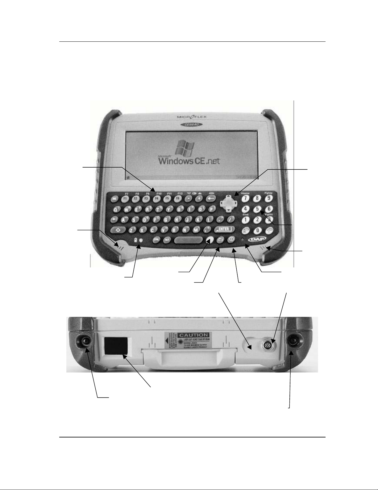
CE8000 & CE8000LS
Front and Top Views
Scree
Functions
Ke
Speake
s
Battery Indicator
Blue Ke
Folder Key (DapShell) ON Ke
Location fo
optional
Second LEM
Cursor Pa
umeric
keypad
Microphone
Laser Light Indicato
First LEM
communication
connecto
FIGURE 1
FRONT AND TOP VIEWS
_MAN40-A (CMU040-A3)
Barcode Laser Scanner (CE8640LS)
Carrying strap fastener for
ri
ht handed people
Laser Trigge
r
y
15
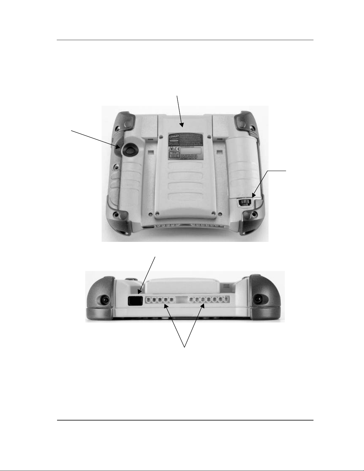
CE8000 & CE8000LS
Rear and Bottom Views
PCMCIA Sockets and Expansion Ba
Release
screw for
the battery
FIGURE 2
REAR AND BOTTOM VIEWS
IrDA Port
Charging Contacts &
Communication Connectors
(Depends of options)
_MAN40-A (CMU040-A3)

16
CAUTION
–
CE8000 & CE8000LS
SECURITY NOTICE
other than those specified herein may result in
Use of commands or procedure
hazardous laser light exposure.
Do not intentionally look at the laser beam
SECURITY NOTICE
_MAN40-A (CMU040-A3)

CE8000 & CE8000LS
N
l
n
n
KEYBOARD TEMPLATE VIEW
17
Alpha Sectio
umerica
Sectio
FIGURE 4
KEYBOARD TEMPLATE VIEW
_MAN40-A (CMU040-A3)

18
_MAN40-A (CMU040-A3)

19
GET STARTED
The information in this manual refers to the CE8000
Series unit. This is a generic name regrouping both
CE8000 and CE8000LS
Consequently, except where otherwise indicated, it
covers information for the CE8000 and CE8000LS.
Your new CE8000 Series unit comes with partially charged main and backup
batteries. It is highly recommended to do a full recharge of them before using
the unit.
All CE8000 Series unit are shipped with and uninstalled battery.
Follow these steps to install the battery in the CE8000 Series unit:
• Place the battery into the compartment found at the back of the unit
• Press and old down the battery while turning the wheel to the
direction of the closed lock (see pictogram near the wheel).
If the wheel is not completely closed, the unit will not start even
if a charger is present. A warning message will be display on the
CE8000 unit to ask the user to correctly close the wheel.
Recharging
The Battery
The CE8000 Series unit normally ordered with a charging kit. A choice of
several charging kits is available.
- The ASCE800 or ASCE802 allows charging the CE8000 Series from the
LEMO type connector.
The specific kit required depends on the type of power available for the
charger:
- The ASCE800 for charging from a 110 V, 50-60 HZ source
- The ASCE802 for charging from a 220 V, 50-60 HZ source
The charging operation is completed within five (5) hours. The CE8000 Series
unit intelligent charging system will stop by itself when the battery is
completely recharged.
_MAN40-A (CMU040-A3)

20
Align red dots then insert
=== IMPORTANT ===
The recharging must be done when the battery is at a temperature
between 5°C (44°F) and 45°C (113°F) to preserve the battery
integrity. The Battery Status Indicator goes yellow if the battery is too
hot or cold to be charged and the charging system is disabled.
From The
LEMO
Connector
The installation requires the modular charger and the communication cable
from the LEMO Connector Charging Kit (part number ASCE800 or
ASCE802).
Insert the round connector of the modular charger into the round connector of
the small cable attached to the communication cable’s 9-pin connector
(Figure 4). Connect the modular charger to the wall outlet.
Communication connector
Round connector
(Insert and tighten)
connector
Note: Do not twist the LEMO connector when inserting or
FIGURE 3
CHARGING FROM THE COMMUNICATION CABLE
removing the cable
_MAN40-A (CMU040-A3)

Communication
Cradle
Automatic
Shutoff
21
Align the red dot located on the LEMO connector’s end of the cable with the
red dot found on the round connector located on the top right of the CE8000
Series unit and insert connectors one into the other.
Note: For communication, if your CE8000 Series unit has two
round connectors (LEMO connector) use the right one.
Either of them can be used for charging.
The Battery Status Indicator (Figure 2) will turn red in the next five (5)
seconds indicating that charging is in progress and will become green when
the full charge is completed. This could take up to five (5) hours. The led
could turn on immediately green if the unit is fully charge.
If the unit was turned off, it should turn back on after a few seconds.
Processing will resume exactly where it was interrupted once recharging
starts.
No information where available at the time this document was printed
You generally do not have to worry about turning off the CE8000 Series unit
to save the battery. If the unit remains inactive for more than three minutes, it
will turn off automatically. The unit will save the exact status of your
application program and data before turning off.
The CE8000 Series unit is turned off when the display is empty and the
keyboard does not beep when a key is pressed. To restart, use the normal
start-up procedure. Once restarted, you can resume your task where you left
off.
When turned off with fresh batteries, you can store the CE8000 Series unit
for several days without needing to recharge them. Refer to section
MAINTENANCE AND STORAGE for more information about storing the
unit.
Turning The
Unit ON
Simply press the key on the keyboard. The CE8000 Series screen will
normally activate.
It could occur that the battery is really too low to start the unit when pressing
the
section GET READY to know how to charge it.
Out of the charger, the unit will normally turns off by itself after about three
(3) minutes.
To turn ON the CE8000 Series unit, simply press the
keyboard. The unit screen will normally activate.
It could occur that the battery is too low to start the unit when pressing the
changing instructions.
key. In that case refer to paragraph “Charging the battery” under
key on the
key. In that case refer to section BATTERY AND CHARGING for
_MAN40-A (CMU040-A3)

22
Turning The
Unit OFF
Manually
Battery
Status
Indicator
To turn off the CE8000 Series unit press the following keys: blue key and
one after the other (releasing the previous key before pressing the next).
The display will clear and the keyboard will no longer beep when a key is
pressed.
To restart, use the normal start-up procedure.
NOTE: The device will not turn off when charging.
While charging, the Battery Status Indicator has several meanings.
COLOR MEANING
Red, continuous
Green, continuous
Red, blinking
Yellow, continuous
Yellow, blinking
Turned off
FIGURE 4
MEANING OF THE BATTERY STATUS INDICATOR
Charger connected, unit is charging
Charger connected, unit fully charged
User’s defined low battery warning
Charger detected but the battery temperature
is too high or low to be recharged. Charging
will start when temperature will be adequate.
Charging disabled by the application program
(as with BATMNGR)
Power from the charger not detected
_MAN40-A (CMU040-A3)

Touch Screen
Calibration
23
You might have to calibrate the touch screen when you receive a new unit or
after you have stored the unit for a long period of time without recharging. In
this case, the display of the Figure 6 will appear.
Calibration is simply done by touching the center of the cross a couple of
seconds. When the cross moves to another place repeat the operation.
Hold your pen until
the cross moves.
Starting
Display
FIGURE 5
CALIBRATION OF THE TOUCH SCREEN
If the unit is new and no software has been loaded yet, the screen you see
should look a bit as the one in Figure 7 otherwise the main display can be
different.
Activate DapShell by pressing the
(Folder key)
FIGURE 6
EXAMPLE OF A STARTING DISPLAY
_MAN40-A (CMU040-A3)

24
TO SEE MORE
N
r
Use of the
Touch Screen
The touch screen is very user friendly. You simply have to use the special
Stylus/Pen provided by DAP Technologies.
Double-tap on a folder
FIGURE 7
USE OF THE TOUCH SCREEN (1)
to open it.
To move a file to a folder, touch
the file with your stylus and drag it
into the folder.
OBJECTS
Move the navigation
bar by sliding your
Stylus/Pen on the
avigation Ba
or
click the Navigation
Arrow
FIGURE 8
Caring of the
Touch Screen
With minimal maintenance and if you avoid using abrasive or metallic pointer
on the touch screen it should last for many years. Use a normal soft cloth and
mild soap to clean the touch screen of the CE8000 Series unit. Do not use
abrasives as they may damage the finish.
_MAN40-A (CMU040-A3)

Loading files
and programs
25
Do not use any other Stylus/Pen than the one provided by DAP
Technologies. If not, it may damage your touch screen.
Replace or clean the stylus as soon as it seems damaged or dirty
Your CE8000 Series unit is now operational.
You might have to do all the previous steps if you store the unit for a long
period of time and lose your data. For more information about storing the unit,
refer to section MAINTENANCE AND STORAGE.
The loading of files and programs on your device depends of your application
and could require the installation of programs on a desktop computer.
Please refer to the instruction for your application or contact your supervisor.
For technical people or programmers, see the section ADVANCED USER
INFORMATION
No information where available concerning ACTIVE SYNC at the time
this document was printed
_MAN40-A (CMU040-A3)

26
_MAN40-A (CMU040-A3)

Battery Power
Management
27
ADVANCED BATTERY OPTIONS
All CE8000 Series unit are delivered with a main battery already calibrated
but you might need to make a new calibration to get better precision. Using
the BatMngr applet you will be able to manage all power properties like the
warning level and power off options.
Double tap on
Figure A Figure B
Figure A and B shows that the default power properties are set to:
This setting means that the CE8000 Series unit battery status monitor will
start flashing red when it remains 16% of the complete charge on the main
battery
You will see the Main Battery field becoming highlighted Low under the
Status tab (Figure A). It will stay highlighted as long as the battery level is
between 6 and 16.
At 5%, the battery status monitor will still continue to flash and a pop-up
window will be displayed telling you that your main battery is very low on
power. Messages will be displayed every four (4) minutes approximately. The
Main battery field is highlighting Very Low (Figure A). It will stay
highlighted as long as the battery level is lower or equal to 5.
See section
appearing when going out of battery power.
(Low Battery Message) for description of the different messages
and then select the tab name Warning
Low level = 16%
Very Low level = 5%
_MAN40-A (CMU040-A3)

28
,
Low Battery
messages on
Main Battery
Main Battery
Very Low
You can change these settings to match it to your needs when your batteries
are going down.
For more information about the Battery Power Management on a Microflex
CE8000 Series unit call the Technical Support or go to DAP web site.
Note
Calibration will always stay valid for all CE8640 Series
battery but if the delay between two calibrations is to long
return information will be less accurate.
After several hours of usage, the main battery will become low. Two
different Low Battery messages will tell you that the main battery needs to be
recharged (Figure 13 and Figure 14).
Main Battery
Expired
The Main Battery Very
Low appears when there is
still some power to continue
to work.
The level at which it
appears is adjustable by an
advanced user see previous
section Battery Power
Management
Press ESC or tap the X to
clear the message.
FIGURE 9
MAIN BATTERY VERY LOW
It will re-appear from time to time about every four (4) minutes to remind you
to charge the unit.
The Main Battery Expired
appears when the power is
really too low to power the
unit anymore.
It is then better to
shutdown your device
immediately by tapping
Shutdown. Otherwise the
FIGURE 1 0
MAIN BATTERY EXPIRED
device will turn off by itself
after 30 seconds.
_MAN40-A (CMU040-A3)

Low battery
messages on
Backup Battery
29
If the user persists to use the unit after this message appears, it is possible
that the unit does not turn-off properly and reboot when you will start to
charge it. Upon reactivation, a message indicating that the system has been
improperly RESET by a LOWBAT may appear on the screen.
The CE8000 Series backup battery allows you to keep programs and files in
the memory for days. In practice, the backup battery is used only while you
replace the main battery, when the main battery is absent or when the main
battery power is expired
Even if the main battery is too low to power the CE8000 Series unit, enough
energy remains to power the memory for a period of about 36 to 60 hours
without using the backup battery.
The backup battery will be turned on to maintain the memory only when the
main battery is completely dead.
The backup battery is recharged every time you recharge the unit. The
backup battery is also recharged from the main battery even if the unit is not
charging.
NOTE: The life duration of the backup battery depends on:
- The residual power of the main battery.
- The quantity of memory installed in the CE8000 Series unit.
Memory is kept between 24 hours to 2 days.
NOTE: The backup battery capacity decreases greatly at
FIGURE 11
BACKUP BATTERY LOW
temperatures below 0°C.
The Storage Flash memory requires no power from the
backup battery.
When the Backup Battery Low
message appears the data is still
secure but the backup battery needs to
be recharged.
_MAN40-A (CMU040-A3)

30
Replacing the
main battery
When the Backup Battery Very
Low message appears the backup
battery is so low that data and
programs could have been corrupted.
FIGURE 1 2
BACKUP BATTERY VERY LOW
It is preferable to replace the main battery in a clean and dry area. Make sure
that neither water nor dust can enter the CE8000 Series unit.
NOTE: The CE8000 Series unit as an integrated hardware/software
The CE8000 Series unit uses a specifically designed and tested main battery
to insure quick charging time, long-battery life and to withstand shocks and
vibrations. To be sure that the battery is conform for usage on a DAP
equipment, buy them directly from DAP TECHNOLOGIES or one of its
distributors (Part number DCCE800-Y or DCCE800-G) and check for the
DAP label on it.
Replacement of the main battery is an easy task. Follow the steps outlined
below.
system that allows user to remove the battery without
having to turn off the unit.
Even if the system is safe enough in most applications, we
highly recommend to turn-off the unit before removing the
battery
FIGURE 13
BATTERY COMPARTMENT
_MAN40-A (CMU040-A3)

31
S
To remove the battery:
Turn-off the unit. On the back of the CE8000 at the bottom right corner, turn
the wheel in the direction of the open lock to release the battery (see
pictogram near the wheel).
To install the battery:
Place the battery in the compartment then press and old down the battery
while turning the wheel to the direction of the closed lock (see pictogram near
the wheel). The wheel must be tightened completely to allow the unit to start.
If the wheel is not completely closed, the unit will not start even if a
charger is present. A warning message will be display on the CE8000
unit to ask the user to correctly close the wheel.
BATTERY PRECAUTION
WARNING: Personal injuries may result if batteries are not
• If the battery becomes unusable, dispose of it immediately.
• Keep the batteries away from heat sources, including open fires
and direct sunlight.
• Never disassemble a battery.
• Do not place batteries through metal pieces that can short-circuit
the power contact pin.
handheld with care
Recycling the
battery
The type of main battery used in all CE8000 Series units is not considered as
a hazardous waste. Refer to your local regulation for the proper methods of
disposal.
_MAN40-A (CMU040-A3)

32
d
Power Gauge
Calibration
with
BatMngr.exe
The CE8000 Series unit includes a Power Gauge to monitor the power
remaining in the main battery at any time (Good, Low, Very Low). This
gauge indicates the estimated remaining time and percentage.
The Battery Status indicator will flash when the battery reaches the Battery
Warning Level.
To get a better precision with the warning level messages, it is recommended
to recalibrate the battery on a regular basic. This process can take up to 16
hours.
NOTE: A non-calibrated power gauge DOES NOT affects neither
the battery life nor the charging duration. The calibration
only allows the CE8000 Series unit to accurately report the
remaining capacity of the main battery and to enable the
Battery Status indicator to blink when the battery reaches
the Warning Level. A CE8000 Series unit can be used with
a non-calibrated power gauge.
You can start the application by pressing CTRL and F2
Note: Shortcut Key could have been deactivated
Tap on the File menu an
select Start
Calibration
FIGURE 14
STARTING POWER GAUGE CALIBRATION
Result of the calibration will be given at the end of the cycle.
Note
Calibration is maintained into the battery pack. This means
that you can calibrate a battery on one unit and use it on any
other CE8640 Series unit with preserved calibration.
_MAN40-A (CMU040-A3)

BATMNGR
Typical
Values
33
The BATMNGR program can also be used from time to time to check the
main battery quality. As a guideline, a fresh battery should give the typical
following values. The previous readings done with the same battery also need
to be compared to know the actual battery capacity and tendency.
CE8000 & CE8000LS
Minimum Value Typical Value
First
charge
Discharge
Second
charge
Capacity
FIGURE 15
BATMNGR TYPICAL VALUES
If values are far from the typical values it is suggested to:
· Run another BATMNGR and compare the numbers.
If it still remains with values far from the typical values:
· Replace the battery,
· Call DAP Technologies Customer Support.
Non-relevant Non-relevant
Not Available 431
Not Available 139
--- 2000mAh
_MAN40-A (CMU040-A3)

34
_MAN40-A (CMU040-A3)

Multi-key entry
Auto-repeat
Digit and letter
keys
Lower case/
Upper case once
Lower case/
Upper case
continuous
35
USE OF THE KEYBOARD
Sometimes you might need to press more than one key to get a character or a
special function. The SHIFT (Ï), CTL/ALT or blue key are the keys that
can precede a letter or a digit to modify its original value.
According to your preferences or as the situation demands, you can decide to
use one of the two following methods to form the sequence of keys:
- Press the keys one after the other, releasing the previous key before
pressing the next. This method (also known as one finger typing) allows
you to use only one finger to make any function
Or
- You can press all of the keys required together, using two or more fingers.
The colour code simplifies the way the keyboard works. The blue key needs
to be pressed first to get a character in blue.
A simple way to understand how the multi-key entry works is by typing a ?.
The ? Being in blue means that you must precede it with the blue key that is
also in blue. You may use either method described above.
A key will automatically start to repeat if left pressed for more than one
second. It will stop repeating once released. This delay is configurable using
the Control Panel / Keyboard applet.
To generate a character either as an alpha (letter) or numeric (digit) value,
simply press the key corresponding to the desired letter or digit. Letters are
normally all in lower case.
To generate an upper case letter, press the following keys: the SHIFT (Ï)
followed by the desired letter.
To generate a series of upper case letters, first press the blue key then the
Punctuation and
special symbols
Function keys
(F1…F6)
. This will do the same as the Caps Lock key you find on a
conventional PC keyboard.
To enter punctuation marks or special typographic symbols, press the blue
key and then the letter key marked with the desired symbol in blue. To
generate a ?, press the blue key and then /.
The function keys are for direct access to a specific function in your
application. Function keys F1 to F6 are direct access. F7 to F12 are also
available with pressing the blue key. Other functions might be attached to
keys SHIFT (Ï) F1 to F6 and CTL F1 to F6.
_MAN40-A (CMU040-A3)

36
Activating the
backlighted
screen and
keyboard
Please refer to your Application User’s Guide to know the intended meaning
of these keys.
To use the unit in a low-light environment, every CE8000 Series unit is
equipped with a backlighted screen. Optionally, CE8000 Series unit can also
be equipped with a backlighted keyboard.
NOTE: Backlighting can drain batteries rapidly if used constantly.
To activate the backlighting of the screen and keyboard, press the blue key
and then the
feature.
Backlighting normally turns off by itself after 45 seconds if there is no key
pressed or new information on the screen.
The backlighted keyboard has two distinct zones: (Figure 1)
Only use it when necessary in a low-light environment.
backspace key. The same sequence will deactivate this
• The numerical section
• The alpha section
Additional
Adjustment on
the Display
Background and
Contrast
Other Special
Keys
Normally, both zones of the keyboard will be backlighted but under software
control only one zone at a time can be backlighted.
The CE8000 Series unit includes a precise automatic temperature
compensation system to assure you that the screen display contrast will be at
its best in any circumstance. In extreme temperatures outside of the -20 to
+50°C (-4 to +122°F) range, or simply to adjust it to your preference, you
may have to manually readjust it.
In extreme low temperatures, pressing the blue key and then the
one after the other can increase the display contrast. You can hold down the
+ sign key
+ sign key to take advantage of the keyboard repeat function and go quickly
from one step to another.
In extreme high temperatures, pressing the blue key and then the
one after the other can reduce the display background darkness. You can
hold down the
and go quickly from one step to another.
The tab key . It is used in the same way as the one found on desktop
computer
Other popular special keys are shift 0 to shift 9 (Ï0 to Ï9), and Ï. They
respectively give these characters: ) ! @ # $ % ^ & * and (
- sign key to take advantage of the keyboard repeat function
- sign key
_MAN40-A (CMU040-A3)

37
yp
p
r
The CE8000 Series units also have pre-defined function keys available to all
users.
Starts a connection with the host computer
F1
SHIFT (Ï) + F1
CTL + F1
CTL + F2
CTL + Folder
ALT-ESC
ALT-TAB
All these pre-defined functions keys are available at the initial start-up of the
CE8000 Series unit. Some pre-defined functions keys like SHIFT (Ï)+F1,
CTL+F1 can be associated with other programs or task. Refer to “DAP
Shell Usage” on DAP Technologies website for complete information about
viewing or changing these functions keys.
ActiveSync must be install on the host computer
Allow to select a connection t
a synchronisation with ActiveSync
Starts REMNET.EXE to create a new
connection
Starts BATMNGR.EXE to calibrate the
gauge
Activated/de-activated the taskbar
Show the Task Manager
Toggle between running task
e used to make
owe
All those function keys may have been disabled by an application or
could have been set with other usage that the one pre-defined at the
initial start-up.
_MAN40-A (CMU040-A3)

38
_MAN40-A (CMU040-A3)

39
USE OF PC CARDS
PC Card sockets are located inside the Expansion Bay. To insert, remove or
swap a PC Card, follow the steps described below.
NOTE: It is preferable to insert, remove or replace a PC Card
PC-CARD AND EXPANSION BAY
1. Turn off the unit.
2. Using a small flat blade screw driver remove the Expansion Bay cover by
loosening the four screws located on the back of the unit, about two turns
to the left (counter-clockwise).
in a clean and dry area. Make sure that no water or dust
will enter the CE8000 Series unit
Four screws to be
removed from the
expansion cover to
access the
PCMCIA Socket
_MAN40-A (CMU040-A3)

40
r
r
3. Remove the expansion bay cover by lifting it and slide it toward the front.
2.- Slide the
cover toward the
front of the unit.
1.- Pull up the cover.
4. To remove an actual PC Card, if present, press the appropriate release
button located on the side of the card. The card will exit the socket by a
few millimeters. It is preferable to use a finger, as a protection to stop the
card. Complete the removal by pulling out the card.
5. To insert a PC Card, slide it in the socket (the end with the two rows of
little holes first and the manufacturer label on top). When the sliding begins
to be a bit tight, push the card firmly. The release button should pop out
and the card should hold firmly in the socket. If this is not so, the card is
possibly upside down. Before closing the cover, check the plastic gasket
located around the internal side of the expansion bay. It should be in good
condition, perfectly clean, with no dust, sand, grease, oil or other
impurities. Any fault in this aspect could cause the PC Card door to leak
and eventually damage the unit. The longest card must me placed in the
lower PCMCIA Socket
6. On the cover of the expansion bay, adjust the PCMCIA Card stopper.
Loosen the two screws and sliding up or down the two stoppers. While the
card is installed in the socket, report the first number that will be displayed
at the top of the installed card and set the stopper found on the cover at
the same number. The stoppers are there to keep the cards in place and
also help them to absorb shock and vibration.
_MAN40-A (CMU040-A3)
Turn the longer stoppe
upside down for longer
PCMCIA Card
Use the shorter stoppe
for the upper PCMCIA
Card
PCMCIA
Card
Stopper default position
7. To close the cover, replace the cover on its initial position. Tighten the four
screws, about two turns to the right (clockwise). Tighten them until you
feel some resistance. Do not over tighten
8. Turn on the unit, the application program should run normally after these
steps.

41
IrDA INTERFACE
The CE8000 Series unit comes with an integrated IrDA interface. See Figure
3 and Figure 4 to locate the IrDA interface.
An IrDA interface is an advanced technology that allows Infra Red
communication with peripherals and between computers. On CE8000 Series
unit, the main purpose of an IrDA Interface is to communicate with a printer
without any cable attachment. Communication with another computer or even
another CE8000 Series unit is also possible.
The way the printing is done using IrDA is mainly dependent on the
application program. You should refer to your application program user’s
guide for complete details.
CE8640 & CE8640LS
The following is basic information on IrDA.
· To communicate with the IrDA interface, the peripheral or the remote
computer should also have an interface supporting the IrDA protocol.
· To communicate with the peripheral, point the bottom side of the
CE8000 Series unit at the IrDA receptor on the peripheral. Usually the
receptor looks like a dark plastic window about 17 x 7 mm (3/4" x 5/16").
Stay aligned within about ±15°
· The communication can be done from a distance of up to one meter
(three feet).
· The communication link is strong enough to withstand quite a large
displacement between the computer and the peripheral. In case of bad
reception, the communication protocol will restart the transmission of the
missed data block.
· Direct, strong sunlight can degrade the communication link, increasing
the communication duration or even causing a breaking of the link.
Under direct sunlight, protect the CE8000 Series unit and the peripheral
with the shade of your body and keep units closer to the peripheral.
_MAN40-A (CMU040-A3)

42
_MAN40-A (CMU040-A3)

43
BARCODE LASER SCANNER
(CE8000LS)
The CE8000LS is a standard CE8000 on which a Laser Barcode Reader has
been installed.
The functioning of the Laser Barcode Reader is mainly under the control of
an application program and a special software driver. You should refer to
your application program user’s guide for complete details.
The following is basic information on laser barcode reading.
• Point the top of the CE8000LS toward the barcode label to read.
• Press the SCAN Button found on the back of the unit and move the
CE8000LS back and forth to assure you that the beam will completely
cross the label.
Two proper ways to scan a label
1
2
Laser Button at
the back of the
unit
Two improper ways to scan a label
2
FIGURE 16
SCANNING A LABEL
• You will hear a short beep when the label is decoded and the laser led
will turn green.
• You can release the SCAN Button at any time to stop the scanning.
Two short beep will be generated to indicate the end of the scanning
• If you keep the SCAN Button pressed for too long the scanning will
stop by itself after a certain time. You will hear two beeps meaning that
no barcode has been decoded.
Refer to the CE8000 Series Technical Guide for more information about
usage and the programming.
CAUTION - Use of controls, adjustments or performance of procedures
other than those specified herein may result in hazardous laser light
exposure.
1
Do not intentionally look at the laser beam.
_MAN40-A (CMU040-A3)

44
Maintenance
Notice
Plastic Windows
CE8000LS
The efficiency of the reading depends on the quality of this
plastic window. TAKE PARTICULAR CARE OF IT
· Any scratch, dirt or finger mark will degrade the reading
quality.
· To clean, use a soft cloth with soap and water. Any plastic
lens cleaner will also do the job.
_MAN40-A (CMU040-A3)

45
USE OF THE CRADLE
For information about the installation and configuration of all different types of
cradle available for CE8000 Series unit, please refer to the document named
TB40-A.
tb46-a.pdf document content information about:
The
Office cradle
CBCE840-1 Charge & Communication:
CBCE840-2 Charge & communication:
CBCE840-3 Charge & communication:
CBCE840V1
CBCE840V2
CBCE840V3
No more information where available at the time this document was
printed
Serial (RS232) & USB (slave)
Serial (RS232) & Ethernet
Charge & Communication:
Charge & Communication:
USB (slave)
Vehicle cradle
Charging only
Serial (RS232)
4 x serial ports (RS232)
_MAN40-A (CMU040-A3)

46
•
_MAN40-A (CMU040-A3)

47
EXTERNAL COMPACT FLASH
ADAPTER
No information where available at the time this document was printed
_MAN40-A (CMU040-A3)

48
_MAN40-A (CMU040-A3)

Main Battery
maintenance
49
MAINTENANCE
The CE8000 Series units are reliable instruments and require little
maintenance. Only occasional replacement of the battery and strap is
required.
It is important not to leave the CE8000 Series unit exposed to the sun for long
periods of time since the airtight casing may accumulate sufficient heat to
cause a malfunction.
NOTE: There are no user serviceable parts inside the CE8000
Series unit. Do not try to open the case. Any attempt to do
so may affect the weatherproofing, damage the unit as well
as void the warranty.
The high quality Lithium-Ion battery installed by DAP in your CE8000 Series
unit is specified by the battery manufacturer to be rechargeable over 500
times. If you find that the batteries are not lasting for the normal period (at
least 8 hours) after having been recharged, it may be time to change them.
When used under normal conditions, the main battery should last, on average,
from 12 to 24 months.
Backup
Battery
Maintenance
Cleaning
Shipping The
Unit
The CE8000 Series backup battery allows you to keep programs and data in
the CE8000 memory for years without being replaced. Being rechargeable
and protected against deep discharge, the backup battery will not need to be
replaced during the expected lifetime of the CE8000 Series unit.
Use a normal soft cloth and mild soap to clean the CE8000 Series unit. Do
not use abrasives as they may damage the finish.
Make certain that the battery compartment and PC-Card door are correctly
closed before starting the cleaning operation.
The CE8000 Series units have been designed to resist the vibration and shock
that can occur during normal use of the product. However, if it is necessary
to ship one of these units any long distance, the handling involved in land and
air transportation can often subject these units to impact beyond that for
which they where designed to withstand. It is therefore essential that the
CE8000 Series units be properly packed in an adequate and appropriate
manner before being shipped.
The packing box that DAP TECHNOLOGIES uses for shipping the CE8000
Series unit to its customers was designed for this very purpose and should,
therefore, be set aside and kept in case reshipping becomes necessary.
_MAN40-A (CMU040-A3)

50
Carrying
Strap
Maintenance
List of User
Replaceable
Parts
The carrying strap requires no specific maintenance. Use a normal soft cloth
and mild soap to clean it.
It may be necessary to replace it from time to time due to wear.
There are few parts that the user can easily replace on the CE8000 Series
unit. The following list shows parts that need to be replaced occasionally as
they deteriorate with use.
Part Number Description
DCCE800-Y (Yellow casing) Lithium-ion battery pack
DCCE800-G (Grey casing) Lithium-ion battery pack
DCCE801 Carrying strap (four per package)
DCCE500 Stylus / Pen
(Minimum quantity of 5 units)
FIGURE 17
USER'S REPLACEABLE PARTS
_MAN40-A (CMU040-A3)

Short Term
Long Term
51
STORAGE
For a storage period of a few days or weeks it is recommended to keep the
unit on charge. The main battery will fully charge and then the charger will go
in idle mode. Data and programs will be preserved.
NOTE: If not on charge, you may lose your programs and data after
a certain time.
The life duration of the backup battery depends on:
- The residual power of the main battery.
- The quantity of memory installed in the CE8000 Series unit.
Memory is kept between 24 hours to 2 days.
NOTE: The backup battery capacity decreases greatly at
temperatures below 0°C
The Storage Flash memory requires no power from the
backup battery and all data will be always preserved.
For a longer storage period, such as months, remove the battery from the unit
and store the unit as long as you wish. The battery manufacturer
recommends storing the battery partially charged.
It is a good practice to recharge the battery once a year for a couple of
hours.
Before using the CE8000 Series unit again, keep it on a charger for a period
of about 60 hours. This will assure you that the backup battery is fully
charged. Otherwise, a 12-hour period on the charger will be enough to assure
you sufficient protection especially if the unit is going to be recharged almost
every other day. The backup battery will complete its charge during these
periods.
NOTE: When charged, the CE8000 Series unit will restart as if it
NOTE: It is preferable to store the unit at a temperature from 0°C
were new. Refer to section GETTING STARTED for
starting procedures.
(32°F) to 25°C (77°F).
_MAN40-A (CMU040-A3)

52
_MAN40-A (CMU040-A3)

TROUBLESHOOTING CHART
Problems Possible Causes and Solutions
The screen is empty and the
keyboard does not beep
when a key is pressed.
The unit does not turn on
when pressing the
The PC Card does not
connect in the PCMCIA
socket.
Display contrast is weak or
display background very
dark
The unit does not shutoff
automatically or manually.
FIGURE 18
TROUBLESHOOTING CHARTS
key.
The unit is possibly turned off. Press the
key to restart it. (Refer to item “Turning The
Unit On”).
Batteries are possibly too low. Connect the
unit to a charger. The unit should turn on
after a few seconds and restart the operating
system.
The PC-Card is possibly inserted the wrong
way. Refer to USE OF PC-CARD.
The display contrast is incorrectly set. Use
the contrast keys to adjust the display. Refer
to “Display background and contrast,
additional adjustments”.
The display cannot be adjusted correctly if
the unit is used outside of its temperature
limits.
The unit is possibly connected to a charger or
the shutoff feature is not set properly.
53
_MAN40-A (CMU040-A3)

54
_MAN40-A (CMU040-A3)

Operating
Temperature
Rain And Water
Resistance
Resistance To
Shock
Electromagnetic
Resistance
55
OPERATING ENVIRONMENT
The recommended temperature range where the CE8000 Series unit may
be used is from -20°C to +50°C (-4°F to +122°F).
A short exposure to temperatures lower or higher than these could possibly
make the screen very dark or light until the unit returns within the suggested
temperature range.
Long exposure to temperatures below -40°C (-40°F) may damage the screen.
Prolonged exposure to temperatures above +60°C (+140°F) will damage the
main battery and above +70°C may damage the unit (+158°F).
The CE8000 Series unit will withstand exposure to rain without the ingress
of water. It is designed to withstand occasional immersions. The unit floats,
making it easy to retrieve when dropped in water.
These characteristics can be impaired if the battery compartment or the
PC-Card doors are improperly closed or if their gaskets have deteriorated.
The CE8000 unit is designed to withstand shock and accidental drops from
up to 1.2 meters (4 feet) onto concrete within the fully specified temperature
range.
The CE8000LS unit is designed to withstand shock and accidental drops
from up to one meter (three feet) onto a hard surface within the fully
specified temperature range.
It is obvious that these situations should be avoided as much as possible.
The CE8000 Series unit work perfectly well in most common environments
involving electromagnetic fields such as when near power transmission lines,
electric motors, transformers, compressors, low power RF transmitters, etc.
Performance can be degraded when using a communication cable, a
peripheral or a battery charger under these conditions.
_MAN40-A (CMU040-A3)

56
_MAN40-A (CMU040-A3)

ADVANCED USER INFORMATION
Where to find
more information
57
In the objective of giving you the most up-to-date information, advanced user
information is available on the WEB.
Register your unit and get the latest information by following these simple
steps:
• Locate and double-tap the Control Panel folder
• Locate the hardware applet
• Open the Hardware applet.
Note the 16-digit number at
the bottom of the display.
Resetting the
CE8000
Then start your Internet browser and go to the following address
https://www.daptech.com
Do not forget the "s" in the address.
Locate and click the label Register a serial number.
Fill the short form and enter your 16-digit number as the access code.
A set of links will bring you toward the information you need.
NOTE: All these information are not a requirement for adequate
use of the CE8000 Series unit.
There are some specific situations that can cause the CE8000 Series unit to
crash or behave strangely. The most common causes are as listed below:
- Programming errors, specifically when trying a new application program.
- Missing, corrupted programs or data files.
- Operation of the unit outside the specified temperature range.
- Physical abuse. In such an instance, the physical cause will be
observable by examining the unit or looking for plastic cracks or
corrosion marks in the battery and PC-Card compartments.
_MAN40-A (CMU040-A3)

58
They are two ways to reset the CE8000 Series unit
• By Software
(Supervisor mode required)
To access the software reset you must enter the supervisor password. Go
under the Style menu, choose Supervisor Mode and than enter the
supervisor password.
After entering the supervisor password, you will now have access to the
software reset option under the Style menu.
A reset password can be asked to complete the software reset correctly,
contact your system integrator if such password is required.
To do a hardware reset simultaneously press the B + O + S keys for a few
seconds. A message box will be displayed while applications are closed and
the unit will reset at the end of this process.
WARNING: Never remove the battery to reset the unit. This
In all of these cases, contact your supervisor or the application program
supplier. If the problem cannot be resolved, contact the equipment supplier or
DAP TECHNOLOGIES. A reset of the unit may correct the problem or it
may be necessary to return the unit to a DAP Service Center.
_MAN40-A (CMU040-A3)
• By Hardware
can cause the corruption of the running
applications and can also damage the data
present in the Storage Flash.
 Loading...