


GIG-202 Tab
Highlite Interna t ional B.V. – Vestastraat 2 – 6468 EX – Kerkrade – the Netherlands
Ordercode: D2289
MANUAL V1
ENGLISH

Ordercode: D2289
GIG-202 Tab
Table of contents
Warning ............................................................................................................................................................................... 2
Unpacking Instructions ................................................................................................................................................. 2
Safety Instructions ......................................................................................................................................................... 2
Operating Determinations .......................................................................................................................................... 4
Return Procedure .......................................................................................................................................................... 4
Claims .............................................................................................................................................................................. 4
Description of the device ................................................................................................................................................. 5
Features .......................................................................................................................................................................... 5
Overview ........................................................................................................................................................................ 5
Installation ........................................................................................................................................................................... 6
Introduction .................................................................................................................................................................... 6
Ready to start ................................................................................................................................................................ 6
Control Elements ................................................................................................................................................................ 7
Rear panel connections .................................................................................................................................................22
DSP Control .......................................................................................................................................................................25
Mixer interface ............................................................................................................................................................25
Assign interface ...........................................................................................................................................................27
Channel interface ......................................................................................................................................................31
Gate interface.............................................................................................................................................................33
Compressor interface ................................................................................................................................................34
EQ Interface .................................................................................................................................................................35
Routing interface ........................................................................................................................................................36
FX1-2 interface .............................................................................................................................................................37
DCA set interface .......................................................................................................................................................39
Digital In interface ......................................................................................................................................................40
Digital Out interface ...................................................................................................................................................41
Save interface .............................................................................................................................................................42
Load interface .............................................................................................................................................................43
Copy interface ............................................................................................................................................................44
System interface .........................................................................................................................................................45
GEQ interface..............................................................................................................................................................46
FX ........................................................................................................................................................................................47
How to: ...............................................................................................................................................................................52
Assign to a DCA group ..............................................................................................................................................52
Change to mode AUX 1-8 or AUX 1-4/BUS 1-4 ......................................................................................................53
Saving and recalling ..................................................................................................................................................54
Copy channel settings ...............................................................................................................................................56
PFL a channel ..............................................................................................................................................................57
Default settings ............................................................................................................................................................57
Overall PRE/POST switching ......................................................................................................................................58
Installation and connection ..........................................................................................................................................59
Software Update ..............................................................................................................................................................59
Connection Cables .........................................................................................................................................................60
Block Diagram .................................................................................................................................................................61
Technical Specifications ................................................................................................................................................62
1

Ordercode: D2289
GIG-202 Tab
Warning
Unpacking Instructions
Immediately upon receiving this product, carefully unpack the carton and check the contents to ensure
that all parts are present and have been received in good condition. Notify the dealer immediately and
retain packing material for inspection if any parts appear damaged from shipping or the carton itself
shows signs of mishandling. Save the carton and all packing materials. In the event that a fixture must be
returned to the factory, it is important that the fixture be returned in the original factory box and packing.
Your shipment includes:
• GIG-202 Tab digital mixing console
• 19” mounting brackets
• 3-pin IEC power cable
• User Manual
Safety Instructions
Every person involved with the installation, operation and maintenance of this system has to:
- be qualified
- follow the instructions of this manual
Before you initial start-up, please make sure that there is no damage caused by transportation. Should
there be any, consult your dealer and do not use the system.
To maintain perfect condition and to ensure a safe operation, it is absolutely necessary for the user to
follow the safety instructions and warning notes written in this manual.
Please consider that damages caused by manual modifications to the system are not subject to
warranty.
This system contains no user-serviceable parts. Refer servicing to qualified technicians only.
IMPORTANT:
The manufacturer will not accept liability for any resulting damages caused by the non-observance of
this manual or any unauthorized modification to the system.
• Never let the power cord come into contact with other cables! Handle the power cord and all
connections with the mains with particular caution!
• Never remove warning or informative labels from the unit.
• Never use anything to cover the ground contact.
2

Ordercode: D2289
GIG-202 Tab
• Never leave any cables lying around.
• Do not insert objects into air vents.
• Do not connect this system to a dimmer pack.
• Do not switch the system on and off in short intervals, as this would reduce the system’s life.
• Do not open the device and do not modify the device.
• Do not drive the inputs with a signal level higher than required to drive the equipment to full output.
• Do not plug mics into the console (or stage box) while Phantom Power is on. Mute the monitor / Pa
system when turning Phantom Power on or off. Allow the system to adjust for a couple of seconds,
before setting the input gains.
• Only use system indoors, avoid contact with water or other liquids.
• Avoid flames and do not put close to flammable liquids or gases.
• Always disconnect power from the mains, when system is not used. Only handle the power cord by
the plug. Never pull out the plug by tugging the power cord.
• Always operate the unit with the AC ground wire connected to the electrical system ground.
• Make sure you do not use the wrong kind of cables or defective cables.
• Make sure that the signals into the mixer are balanced, otherwise hum could be created.
• Make sure you use DI boxes to balance unbalanced signals; All incoming signals should be clear.
• Make sure that the available voltage is not higher than stated on the rear panel.
• Make sure that the power cord is never crimped or damaged. Check the system and the power
cord from time to time.
• Please turn off the power switch, when changing the power cord or signal cable, or select the input
mode switch.
• Extreme frequency boosts in connection with a high input signal level may lead to overdriving your
equipment. Should this occur, it is necessary to reduce the input signal level by using the INPUT
control.
• To emphasize a frequency range, you do not necessarily have to move its respective control
upwards; try lowering surrounding frequency ranges instead. This way, you avoid causing the next
piece of equipment in your sound path to overdrive. You also preserve valuable dynamic reserve
(“headroom”)
• Avoid ground loops! Always be sure to connect the power amps and the mixing console to the
same electrical circuit to ensure the same phase!
• If system is dropped or struck, disconnect mains power supply immediately. Have a qualified
engineer inspect for safety before operating.
• If the system has been exposed to drastic temperature fluctuation (e.g. after transportation), do not
switch it on immediately. The arising condensation water might damage your system. Leave the
system switched off until it has reached room temperature.
• If your Dap Audio device fails to work properly, discontinue use immediately. Pack the unit securely
(preferably in the original packing material)and return it to your Dap Audio dealer for service.
• Repairs, servicing and electric connection must be carried out by a qualified technician.
• For replacement use fuses of same type and rating only.
• WARRANTY: Till one year after date of purchase.
3
This product should not be placed in municipal waste.

Ordercode: D2289
GIG-202 Tab
Operating Determinations
• This device is not designed for permanent operation. Consistent operation breaks will ensure that the
device will serve you for a long time without defects.
• The minimum distance between light-output and the illuminated surface must be more than 0.5
meter.
• The maximum ambient temperature t
• The relative humidity must not exceed 50 % with an ambient temperature of 35° C.
• If this device is operated in any other way, than the one described in this manual, the product may
suffer damages and the warranty becomes void.
• Any other operation may lead to dangers like short-circuit, burns, electric shock, crash, etc.
= 40°C must never be exceeded.
a
You endanger your own safety and the safety of others!
The GIG-202 Tab is not intended to be used by persons (including children) with reduced physical and/or
mental capabilities or lack of experience and knowledge, unless they have been given supervision or
instruction concerning the use of the appliance by a person responsible for their safety.
Return Procedure
Returned merchandise must be sent prepaid and in the original packing, call tags will not be issued.
Package must be clearly labeled with a Return Authorization Number (RMA number). Products returned
without an RMA number will be refused. Highlite will not accept the returned goods or any responsibility.
Call Highlite 0031-455667723 or mail aftersales@highlite.nl
Be prepared to provide the model number, serial number and a brief description of the cause for the
return. Be sure to properly pack fixture, any shipping damage resulting from inadequate packaging is the
customer’s responsibility. Highlite reserves the right to use its own discretion to repair or replace
product(s). As a suggestion, proper UPS packing or double-boxing is always a safe method to use.
Note: If you are given an RMA number, please include the following information on a piece of paper
inside the box:
1) Your name
2) Your address
3) Your phone number
4) A brief description of the symptoms
and request an RMA prior to shipping the fixture.
Claims
The client has the obligation to check the delivered goods immediately upon delivery for any shortcomings and/or visible defects, or perform this check after our announcement that the goods are at their
disposal. Damage incurred in shipping is the responsibility of the shipper; therefore the damage must be
reported to the carrier upon receipt of merchandise.
It is the customer's responsibility to notify and submit claims with the shipper in the event that a fixture is
damaged due to shipping. Transportation damage has to be reported to us within one day after receipt
of the delivery.
Any return shipment has to be made post-paid at all times. Return shipments must be accompanied with
a letter defining the reason for return shipment. Non-prepaid return shipments will be refused, unless
otherwise agreed in writing.
Complaints against us must be made known in writing or by fax within 10 working days after receipt of the
invoice. After this period complaints will not be handled anymore.
Complaints will only then be considered if the client has so far complied with all parts of the agreement,
regardless of the agreement of which the obligation is resulting.
4

Ordercode: D2289
GIG-202 Tab
Description of the device
Features
● 7” full color LCD touch screen
● Easy to use software interface
● 8 direct access buttons for easy channel control
● Digital Gate/Compressor/4-band full parametric EQ on each input
● 31-band graphical EQ on each output
● 20 analog inputs
● 8 inserts on first channels
● 10 analog outputs
● 100 mm precision motorized fader
● 4 x AUX sends (pre/post switchable per channel)
● 4 x switchable AUX/Subgroups
● 2 x 24-bit FX engines
● Ultra-low noise discrete preamps with +48V Phantom Power
● High-definition ADC’s (114dB dynamic range)
● Integrated USB 2-track recording and playback
● 6 x user-definable DCAs
● Full 24-bit/48KHz sampling rate
● 2 separate volume-controlled headphone outputs
Overview
5

Ordercode: D2289
GIG-202 Tab
Installation
Introduction
The GIG-202 TAB digital mixing console is the first fully digital mixing console in the GIG range from DAPAudio. It is a compact digital mixing console that owns all the features of the more advanced digital
mixers available on the market.
It has 16 XLR/TRS combo inputs and 4 TRS stereo inputs, all equipped with gate, compressor and a 4-band
full parametric EQ on each input channel. The 12 analog outputs feature a compressor and individual 31band graphical EQ. Despite the considerable number of features, DAP-Audio managed to design a userfriendly interface, understandable to all users with or without any experience. To achieve this, DAP-Audio
added dedicated direct access buttons for all important features a sound engineer needs during his
performance. This helps the user to go directly to the desired function without getting lost in complex
menu structures. Direct control is essential in a live situation, therefore the 100 mm motorized fader is
always automatically patched to the main parameter of your selected functionality. This also gives the
console the ‘analogue’ feel to the digital environment.
The GIG-202 TAB features a 7-inch touchscreen, 8 inserts on the first inputs, 4 dedicated AUX outputs plus
4 switchable AUX/SUB outputs, 2 built-in FX engines, 6 user-definable DCAs and internal 24-bit/48kHz
sampling rate make this the most complete and interesting digital mixing console in its market segment.
Ready to start
1) Please check the AC voltage available in your country before connecting your mixer to the
AC socket.
2) Be sure that the main power switch is turned off before connecting the mixer to the AC
socket. You should also make sure that all input and output controls are turned down. This
will prevent damage to your speakers and will help avoid excessive noise.
3) Always turn on the mixer before you turn on the power amplifier; turn off the mixer after the power
amplifier is turned off.
4) Before connecting and disconnecting the unit from the power supply, always turn off the unit.
5) Cleaning: Disconnect the mains power supply and then wipe the mixer with a damp cloth. Do not
immerse in liquid. Do not use alcohol or solvents.
6

Ordercode: D2289
GIG-202 Tab
Green (input detected) / Red color (if the input level is too high, reduce gain)
Turn the controls 1-16 to set the gain level of the channels’ inputs.
overload distortion.
Turn the controls 17-18/19-20 to set the gain level of the line inputs.
overload distortion.
There are 16 select mono channel buttons on the panel.
pressing this button.
There are 2 stereo channel select buttons on the panel.
pressing this button.
Control Elements
Signal / Peak Indicator
Input Level Control 1-16
Note: It is very important to properly set the level of the input gain to minimize noise and avoid
Line Level volume control 17-18/19-20
Note: It is very important to properly set the level of the input gain to minimize noise and avoid
Channel select button
Press this button to route its channel, to add DSP setting and assign its output. It will light up to
indicate that it has been pressed and enabled. In DCA window, you can select group channels by
Stereo line channel select button
Press this button to route its channel, to add DSP setting and assign its output. It will light up to
indicate that it has been pressed and enabled. In DCA window, you can select group channels by
7

Ordercode: D2289
GIG-202 Tab
Output control Sub1/Aux5 - Sets the EQ frequency value.
Output control Sub2/Aux6 - Sets the EQ Q-level value.
Output control Sub 3/Aux7 - Sets the EQ Gain value.
Output control Sub4/Aux8 - Sets the EQ type curve.
Sub1/Aux5 master out control – EQ frequency select
Sub2/Aux6 master out control – EQ Q-level select
Sub3/Aux7 master out control – EQ Gain select
Sub4/Aux8 master out control – EQ Type select
8

Ordercode: D2289
GIG-202 Tab
Press this button to see mixer page on the LCD screen, where you can control all the input and
Press once:
Press twice:
Mixer select button
output channel levels, solo, mute as well as rename the channel. You can control DCA group level
control (see the figure below). For detailed information, see page 25.
9

Ordercode: D2289
GIG-202 Tab
Press this button to enter assign page. Signal from a selected input channel can be assigned to
Press once:
Press twice:
Assign select button
Main, AUX1-4, Sub1-4 or AUX5-8 and FX1-2. See the figure below.
For detailed information, see page 27.
10

Ordercode: D2289
GIG-202 Tab
Noise gate attenuates signals which are below the threshold and allows signals to pass through only
Press once:
Press twice:
Gate/Comp select button
when they are above a threshold setting. Pressing the button twice will switch to the compressor
settings.
The compressor reduces the level of an audio signal, if its amplitude exceeds a certain threshold.
See the figure below. For detailed information, see pages 33-34.
11

Ordercode: D2289
GIG-202 Tab
An equalizer is a filter that allows you to adjust the frequency level in the range of 20Hz-20KHz. See
Press once:
Press twice:
EQ select button
the figure below. For detailed information, see page 35.
12

Ordercode: D2289
GIG-202 Tab
Press this button to show and edit the settings of internal effects. Each FX owns 12 program effects.
Press once:
Press twice:
FX select button
See the figure below. For detailed information, see page 37.
13

Ordercode: D2289
GIG-202 Tab
Press this button to activate/deactivate the digital channel once you have inserted an optional
Press once:
Press twice:
Every microphone input is equipped with an individual phantom power which is controlled by the
Note: Please do not supply phantom power to any device which does not need phantom power.
Otherwise, the device may suffer damage.
Digital select button
input/output module. It will light up to indicate that current channel has been selected as digital
input or digital output. See the figure below.
48V select button
48V phantom power button. When you want to turn on phantom power of some channel, the
screen will show a warning message and will ask you for confirmation. It will light up to indicate that
phantom power is activated. Please note, that only the condenser microphones need phantom
power.
14

Ordercode: D2289
GIG-202 Tab
Input channels, Aux buses and subgroups can be linked as a stereo pair. The button will light up to
Channels 1 and 2
Channels 9 and 10
Aux 1 and Aux 2
Channels 3 and 4
Channels 11 and 12
Aux 3 and Aux 4
Channels 5 and 6
Channels 13 and 14
Subgroups 1 and 2
Channels 7 and 8
Channels 15 and 16
Subgroups 3 and 4
A stereo link can be enabled when either channel in the pair is selected, by pressing the link button.
Apart from link, the channels can also be grouped to DCA as stereo channel, but without the
cannot be linked at all, while its paired channel can link.
For example: channel 5 is linked to channel 6, then both channels can be grouped to DCA.
The two linked channels can route as stereo channel, while routed channels can also link later.
Please note that this is a non-destructive passing. The other channel’s previous setting will be
own settings will be restored after the Link button has been pressed again.
LINK select button
indicate that the stereo link is active. The stereo pairs are predefined and cannot be changed. They
are as follows:
When the Link button is illuminated, indicating that the Stereo Link function is enabled, all DSP
settings, subgroups assignments, solo status and main assignments are passed to the other channel
of the pair.
Link & D C A
possibility to channel the link in DCA. On the contrary, if the channel has been grouped to DCA, it
However, if channel 5 has been grouped to a DCA first, it cannot be linked to channel 6, but
channel 6 can be linked to channel 5.
Link and Routing
restored after the link button gets disengaged. For example, when channel 6 has been selected,
then press the Link button. All of the channel 6 settings will be copied to channel 5. The channel 5’s
15

Ordercode: D2289
GIG-202 Tab
Indicates the output level for a selected channel. If Solo Meter (21) is active, it shows the input
Solo/PFL level of the selected channel.
Indicates the level output for SUB1-4/Aux 5-8.
Indicates the main level volume output.
When pressed, the meter (18) will indicate the level of the selected solo channel(s).
Clear all solo selected channels.
Press these buttons to route its channels to add DSP settings and assign its outputs. It will illuminate
when the function is active.
Press this button to edit the master output channel DSP settings.
Solo/PFL output meter
Level output indicator
Main output level indicator
Solo meter button
Solo clear button
Sub1-4/Aux 5-8 select buttons
Main select button
16

Ordercode: D2289
GIG-202 Tab
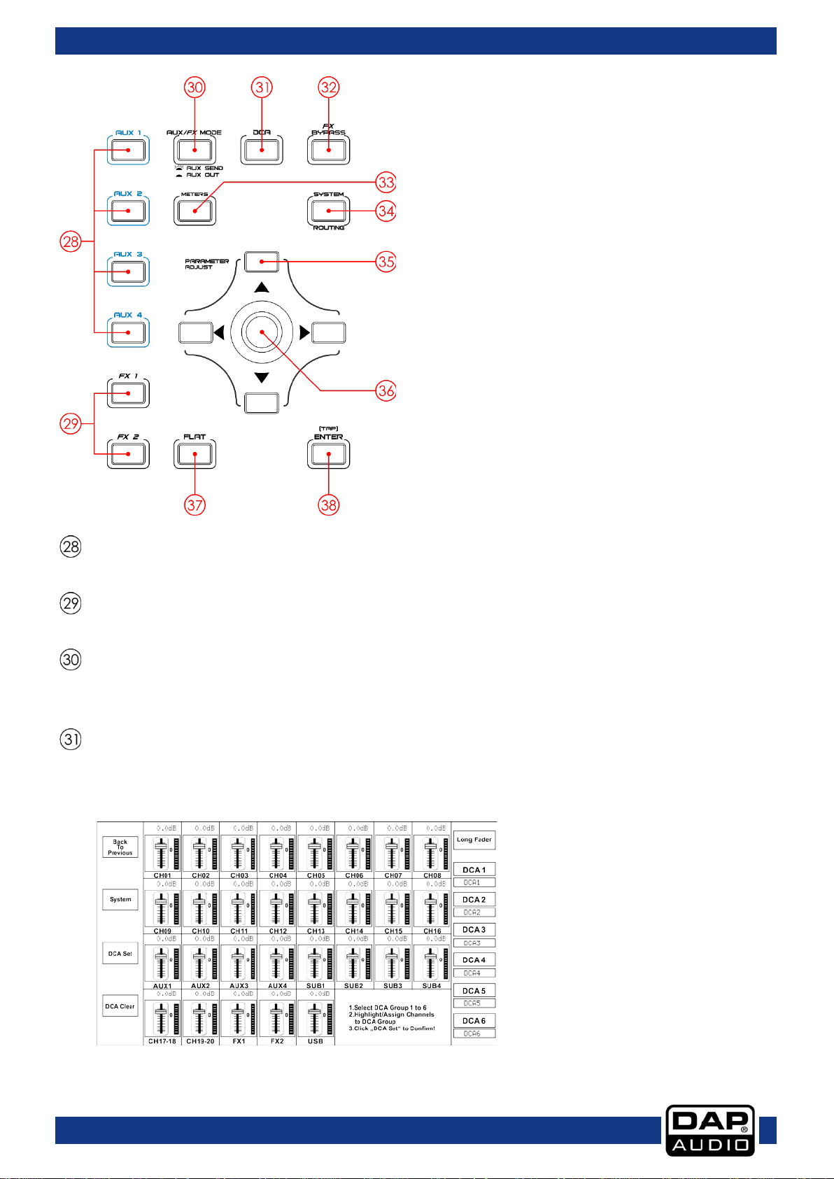
Select one of the 6 DCA groups. The channel fader will be activated for the selected DCA group.
Assign outputs to selected channels and FX channels. Subgroups and Auxiliaries can only be routed
to main.
There is only one motorized fader to control all digital channel levels, including 20 input channels, 1
USB input, 4/8 Aux outputs, 4 Sub outputs, FX channels and 1 main output channel.
66
DCA 1-6 select buttons
Main / Sub 1-4 assign buttons
Motorized fader
17
Ordercode: D2289
GIG-202 Tab
Select Aux 1-4. Press these buttons to add DSP settings.
Select FX 1/2. Press these buttons to add DSP settings.
In Aux send mode (button is illuminated), aux 1-4/5-8 (28) can be used to select the corresponding
used for selecting the auxiliary masters.
Digital Controlled Amplifier (DCA) can perform group assignments. DCA volume control will always
Aux 1-4 select buttons
FX1/2 select buttons
Aux send / Aux Out
aux on the selected channel. In Aux out mode (button is not illuminated), aux 1-4/5-8 (28) can be
DCA set button
leave the same ratio between the channel fader levels, independent of the volume control. If you
press this button, it will flash until channels are selected. Then press again to save the settings.
18
Ordercode: D2289
GIG-202 Tab
Press this button to mute the FX return channels.
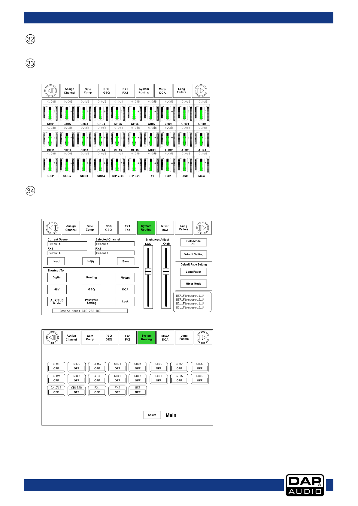
Press this button to get a total overview of all channels.
Press once to access the system menu. Press again to access the routing menu.
Press once:
Press twice:
FX Bypass
Meters
System / Routing
19

Ordercode: D2289
GIG-202 Tab
Navigate through all menus by pressing the up, down, left & right buttons.
This encoder adjusts the parameter values of the selected controls that are shown on the LCD
display.
Pressing this button will reset the EQ settings of the selected channel.
This button has two separate functions:
TAP In the FX menus, the delay time can be tapped.
Adjusts the output volume of the control room.
When PFL is active, the solo button will be in Pre Fader Listening mode.
Adjusts the output volume of the headphones.
Switch to the 31-band graphic equalizer. The GEQ of the selected output will be displayed.
Parameter adjust buttons
Encoder
Flat EQ button
[TAP] Enter button
Enter Confirm the edited parameter values
Ctrl room volume control
PFL button
Headphones 1 & 2 volume control
GEQ button
20

Ordercode: D2289
GIG-202 Tab
Controls the main output volume.
Press this button to send the signal of the selected channel(s) to the control room and headphone
When activated, the selected channel(s) will be muted.
When activated, the selected channel can be panned with the Encoder (36).
Main volume control
Solo button
outputs.
Mute button
Pan button
LCD Touchscreen
21

Ordercode: D2289
GIG-202 Tab
Electronically balanced combo-type input for connecting low impedance microphones.
The INS(ert) connector (¼" stereo jack connector) is used for connecting to external signal
processors.
Electronically balanced combo-type input for connecting low impedance microphones.
Connect headphones.
These are balanced mono outputs for each subgroup.
These are balanced mono outputs for each auxiliary.
Rear panel connections
XLR/Jack combo connector 1 - 8
Insert connectors
XLR/Jack combo connector 9 – 16
Headphones 2 Output
Subgroup outputs
Auxiliary outputs
22

Ordercode: D2289
GIG-202 Tab
Use the POWER switch to turn on the mixing console. The POWER switch should always be in the
“Off” position, when you are about to connect your unit to the mains.
Before connecting the unit to the mains, ensure that the voltage setting matches your local
the unit from the mains, pull out the main cord plug.
This port is for remote control or firmware update.
The CTRL-ROOM outputs will be used to send the signal to studio monitor speakers.
Power ON / OFF
AC Inlet with fuse holder
voltage. Blown fuses should only be replaced with fuses of the same type and rating. To disconnect
USB Audio In/Out
Control Room outputs
23

Ordercode: D2289
GIG-202 Tab
The MAIN MIX outputs are balanced 1/4" TRS connectors. These outputs are parallel to the XLR
Outputs (59).
The MAIN MIX outputs are balanced XLR connectors.
The 19-20 Line inputs are normally used as effect returns. The inputs accept balanced stereo. If a
The 17-18 Line inputs are normally used as effect returns. The inputs accept balanced stereo. If a mono
side will get the signal.
TRS balanced Main Outputs
XLR balanced Main Outputs
TRS balanced Inputs 19-20
mono signal has to be returned to the mix, connect it to the left input and then the right one as well,
as the left side will get the signal.
TRS balanced Inputs 17-18
signal has to be returned to the mix, connect it to the left input and then the right one as well, as the left
24

Ordercode: D2289
GIG-202 Tab
Bus
Gate
Compressor
EQ
Polarity
Pan
Delay
Link
Output Assignment
Input
1-16
Input
17-20
Long fader mode
Mixer mode
DSP Control
The DSP control is the most important function of the GIG-202 Tab. By using it, you can adjust gate,
compressor, EQ, polarity, panning, delay, link, routing, etc. for the selected channels. See the table
below for the list of input/output channels and to see which DSP functions are supported.
Channels
Channels
Aux sends
1-4
FX sends
1-2
Subgroups
1-4
Main
Output
Tape in/
USB
√ √ √ √ √ √ √
√ √ √ √ √ √ X
√ √ √ √ √ √ √
√ √ √ √ √ √ X
X √ √ √ √ √ √
X √ √ √ √ √ X
√ √ √ √ √ √ X
Mixer interface
Turn on the GIG-202 Tab. The mixer interface appears on the LCD touchscreen.
MAIN, Subgroups 1-4,
Aux sends 1-4, FX 1-2
MAIN, Subgroups 1-4,
Aux sends 1-4, FX 1-2
MAIN, Subgroups 1-4,
Aux sends 1-4
Main
MAIN, Subgroups 1-4,
Aux sends 1-4, FX 1-2
The mixer mode depends on the settings, set in the system setup.
Switch between both modes by pressing the mixer button (10).
25

Ordercode: D2289
GIG-202 Tab
Touch the desired channel. The background will light up. Use the Encoder
Move the fader up and down to increase/decrease the level of all input and output
activity.
Touch this icon to monitor the audio signal of the selected channel. The
Touch this icon to mute the audio signal of the selected channel. The icon
Press and hold the “CH01” to rename the channel. The display will show a
The pan indication shows real pan of the selected channel’s audio signal.
Touch these icons to control the channels grouped in DCA1-6. Fo r
the detailed information, see page 39.
Touch these icons to enter the corresponding interfaces.
(36) to adjust the panning.
S/Solo and the Solo button (44) will light up simultaneously.
“M/Mute” and the Mute button (45) will light up simultaneously.
channels, one channel at a time. The meter beside the fader indicates the input signal
The meter located beside the fader indicates the input signal level.
icon will light up together with Solo (44) on the panel.
will light up together with M u te (45) on the panel.
virtual keyboard. Now you can rename the channel.
example, if you touch “DCA2”, its background will light up together with
the DCA2 button (25). Now, move the motor fader and turn the Encoder
(36) or move the fader on the display in order to adjust the signal level. For
26

Ordercode: D2289
GIG-202 Tab
Toggle between Sub1-4 an d AUX5-8 by touching the AUX/SUB Mode icon
in System page.
Touch the Main & Sub 1-4 icons on the display or the Main & Sub 1-4 (26) buttons on the panel to assign
panel.
Touch the AUX 1-4 and FX 1-2 icons on the display or press the AUX 1-4 and FX 1-2 (28/29) on the panel
faders.
Assign interface
Press the Assign button (11) to enter the assign interface. The 20 main inputs, Tape/USB in and internal FX
returns can be assigned to any or all of the subgroup outputs, Aux sends and main outputs.
Sub 1-4 Mode
input channel audio to these channels. When pressed, they will light up simultaneously with the buttons
in Assign area on the panel. In order to adjust the audio output level of the desired channel, turn the
Encoder (36) or touch the corresponding Main or Sub 1-4 (26) controls on the right-hand side of the
to assign input channel audio to these channels. In order to adjust the output level of the channel
audio, turn the Encoder (36).
Touch the PRE icon to switch it to POST. The AUX & FX send will derive its signals from all channels’ postfaders. If the button has not been pressed and is not illuminated, Send will by default derive its signal
from all channels’ pre-faders and channels’ fader positions, unaffected by sending. In other words,
touch the PRE icon and switch it to POST. Now, move the faders to adjust their levels by moving the
27

Ordercode: D2289
GIG-202 Tab
Move the fader to adjust the selected channel’s audio input. The fader’s function is the
“Meter“ indicates the signal level activity.
Press and hold the “CH01” to rename the selected channel.
Move the fader to change the selected channel’s audio output. This fader’s function is
Touch the pan bar on the left or the right side to change signal's balance effect. Its function is the
twice to position the indicator in the center of the bar.
Indicates the assigned DCA Groups of the selected channel.
same as that of the Motorized fader (27) on the panel. While adjusting the level, they will
both change position synchronously.
“Pan” above the fader indicates the pan value setting.
“Solo” monitors the selected audio channel.
“Mute“ mutes the selected audio channel.
the same as that of the Encoder (36).
same as that of the Pan button (46) on the panel. If you have adjusted channel pan, touch the bar
28

Ordercode: D2289
GIG-202 Tab
Touch these controls to enter the corresponding page.
Press a channel to activate phantom power.
Touch this icon to invert the phase of the selected channel's signal (to alter the phase by
If you touch this icon, the background and the Link button (17) will light up synchronously.
Touch “Yes” to activate.
180). If the phase reverse is active, the button will light up. The display shows the phase
reverse setting in real time. The Polarity control can be used for correcting audio signals,
which are out of phase, as well as to cancel/reinforce each other.
The currently active channel will be linked to its peer channel.
29

Ordercode: D2289
GIG-202 Tab
Touch the AUX5-8(SUB1-4) and FX1-2 to assign audio input to these channels or buses. Rotate the
to adjust the volume. The functions of the other icons are the same as those in SUB1-4 mode.
Aux 1-8 Mode
If you switch from Sub1-4 mode to AUX 5-8 mode, you will gain access to more advanced functions.
Encoder (36) to adjust audio output level. You can also use the A ux 5-8 controls (06-09) on the panel
30

Ordercode: D2289
GIG-202 Tab
Touch this icon to invert the phase of the selected channel's signal (to alter the phase by
Touch this icon to switch delay for the selected channel ON/OFF. The icon will light up to
300ms at 48 kHz. The parameters can be adjusted only when the Delay function is active.
When the “Delay icon” is active, touch this icon in Delay Time and rotate the Encoder (36)
to adjust the selected channel’s delay time.
If you touch this icon, the background and the Link button (17) will light up synchronously.
The currently active channel will be linked to its peer channel.
Touch this icon to activate. Assign the signal from the selected channel to the Main
Channel interface
180). If the phase reverse is active, the button will light up. The display shows the phase
reverse setting in real time. The Polarity control can be used for correcting audio signals,
which are out of phase, as well as to cancel/reinforce each other.
indicate that the delay function has been enabled. The delay time can be set up to
channel.
31

Ordercode: D2289
GIG-202 Tab
Touch the “OFF” icon to enable the Gate function. Touch the number
Touch the “OFF” icon to enable the EQ function. It will light up and
Touch the “OFF” icon to enable the Compressor function. Touch the
underneath “Threshold”, then rotate the Encoder (36) or move the long
fader on the right-hand side of the LCD display to adjust the Threshold
value, which will appear in the central box. While adjusting, the changes
will be displayed on the Gate grid.
Touch the grid to enter Gate page. For the detail operation, please refer
to page 33.
synchronize with the ON/OFF control on the EQ page. Please adjust the
values on the EQ page because it is not possible here.
Touch the Flat EQ icon to restore default settings.
Touch the grid to enter EQ page. For detailed information, see page 35.
number underneath “Threshold”, then rotate the Encoder (36) or move
the long fader on the right-hand side of the LCD display to adjust the
Threshold value which will appear in the central box. While adjusting, the
changes will be displayed on the Compressor grid.
In this area, you can touch the grid to enter COMP page. For detailed
information, see page 34.
32

Ordercode: D2289
GIG-202 Tab
Touch this icon to activate/deactivate the Gate for the selected channel. The icon will
Note:
The parameters can be adjusted only if the Gate control has been enabled.
The bar above the “ON/OFF” shows the status of the gate. Red is closed, Green means
opened.
Adjust this control to set the level at which the gate will open. The adjustment range is
Adjust this control to set the amount of time after which the gate should change from
and 200 ms.
Adjust this control to set the amount of time after which the gate should change from
Note:
A fast release abruptly cuts off the sound, once it has fallen below the threshold.
A slow release smoothly changes from open to closed, in a way similar to a slow fade
out. If the release time is too short, a click can be heard when the gate re-opens.
The Gate grid shows the threshold setting in real time.
Note:
You can also rename the selected channel by pressing and holding the CHXX icon.
Gate interface
light up. The display shows the Gate settings in real time. Change the parameters by
turning the Threshold, Attack & Release controls and turn the Encoder (36) to set the
value.
between -84 and +20 dB.
close to open, in a way similar to fade-in function. The adjustment range is between 0.5
open to close. The adjustment range is between 10 ms and 1 second.
The meter on the left indicates the input signal activity.
33

Ordercode: D2289
GIG-202 Tab
Touch this icon to activate/deactivate the Compressor for the selected channel. It will
Compressor has been enabled.
The bar above the “ON/OFF” will light up when a signal is undergoing compression.
Adjust this control to set the compressor’s threshold for the selected channel. If the
the level of this signal. The adjustment range is between -30 and 20 dB.
Adjust this control to set the compressor's attack setting for the selected channel. The
milliseconds.
Adjust this control to set the compressor for the selected channel. Release sets the
drops below the threshold. Release can be set between 10 ms and 1seconds.
Adjust this control to set the compression ratio for the selected channel. The ratio
ratio can be set between Limit and 1:1.
Adjust this control to set the compressor gain for the selected channel or bus. When
adjustment range is between 0 dB (no gain adjusted) and +24 dB.
The compressor grid shows the threshold setting in real time.
Note:
You can also rename the selected channel by pressing and holding the CHXX icon.
Compressor interface
light up to indicate that the compressor has been enabled. The display shows the
compressor setting in real time. Change the parameters by turning the Encoder (36) and
set the values of Gain, Threshold, Attack, Release & Ratio by turning the corresponding
controls or by touching the up & left & down & right keys to choose the function which
you want to modify. Please note that the parameters can be adjusted only if the
amplitude of an audio signal exceeds a certain threshold, the compressor will reduce
attack setting is the period when the compressor is decreasing gain to reach the level
that is determined by the ratio. The adjustment range is between 10 and 150
amount of time it takes the compressor to return to its normal gain once the signal level
determines the amount of gain reduction. For example, a ratio of 4:1 means that if input
level is 4 dB over the threshold, the output signal level will be 1 dB over the threshold. The
compressing a signal, gain decrease will cause the attenuation of the whole level. By
using this Gain control you can recover the lost level and readjust volume. The
The meter on the left-hand side indicates the input signal level.
The meter on the right-hand side indicates the compressor’s degree.
34

Ordercode: D2289
GIG-202 Tab
Touch this icon to activate/deactivate the equalizer for the selected channel. It will light
pressed. The equalizer is available for all input and output buses.
If you touch this icon, a dialog box saying "Are you sure to flat the EQ?" will appear.
choose "no", the settings will be retained.
Adjust this control to separately set the central frequency of the equalizer's Low/Low-
The adjustment range for the central frequency is between 20Hz and 20KHz.
Adjust this control to separately set the Q for the Low/Low-mid/High-mid/High band. The
the Q, the bandwidth will be narrowed. The adjustment range is between 0.4 and 24.
Adjust this control to set the frequency gain for the selected band. The adjustment
This is a low-pass filter and high-pass filter which can pass lower or higher
and different frequency range.
EQ Interface
up to indicate that the equalizer has been enabled. The display shows the EQ setting in
real time. You can adjust the parameters by sliding the curve on the display or by using
the up & left & down & right keys to choose the function which you want to modify and
use the Adjust Parameter control to set the value.
Please note that the parameters can be adjusted only if the EQ button has been
If you choose "yes", all the setting values on this page will be restored to default. If you
mid/High-mid/ High band. The center frequency lies in the middle of the pass-band,
between the lower and upper cutoff frequencies which define the limits of the band.
Q is the ratio of the central frequency to the bandwidth. If the center frequency is
constant, the bandwidth is inversely proportional to the Q, which means that if you raise
range is between -24 dB and +24 dB.
frequencies. When set to its highest position, the filter is off.
Type indicates the filter type. Different filter types provide different shapes
35

Ordercode: D2289
GIG-202 Tab
Adjust EQ1 to separately set its Frequency, Q and Gain
The rotaries (6-9) on the panel can also be used for setting the frequency, Q-factor, Gain and type of
the Low/Low-mid/High-mid/High band.
Adjust this control to route input channel 1 to output AUX1. Rotate the Encoder (36) or
selected channels were linked, they will change synchronously, while being adjusted.
Routing interface
parameters. Touch Type to change the filter to high-pass,
low-pass or band-pass filter; the same as EQ2, EQ3 and
EQ4. The waveform will be displayed.
Select input channels of Main 1-20, FX1-2, USB in and route them to output channels of Main 1-20, Sub 1-4,
Aux 1-4 and FX1-2. See the figure below for Aux 1 routing function. You can route input channels
appearing on the display to Aux1 output. On the Main routing page, channel level cannot be adjusted.
You can adjust it in Sub, Aux and FX pages is adjustable.
move the long fader on the display to change the selected channel's audio level. Touch
the PRE icon to switch it to POST, and the background will light up green. The selected
channel will derive its signals from all channels’ post-faders. If the button has not been
pressed and is not lighted, then, by default, the selected channel will derive its signal from
all channels’ pre-faders and, unaffected by the sending channel's fader position. If the
36

Ordercode: D2289
GIG-202 Tab
Move the fader or rotate the Encoder (36) to adjust level of the selected input channel.
Adjust the effect parameters by rotating the Adjust Parameter control or moving the fader on the
right-hand side of the display.
Touch this icon to mute current FX effect.
FX1-2 interface
Save the setting values FX1-2 as a preset by touching the Save button and following the instructions on
the display.
The GIG-202 Tab includes 12 kinds of adjustable effects. For the detail operation, see page 47.
37

Ordercode: D2289
GIG-202 Tab
Nr.
Preset
Description
Parameter
Simulate the transducer's sound,
plate
Simulate the sound effect by
quickly
Simulate to play with another
on the same instrument
Use a single instrument sound to
more than one instrument
Pre Delay; Rev Decay ; Room Si ze ;
Hi; Echo F.B; Echo out; Dry Out
Out; Dry Out
Out
Out
List of FX presets
01 Hall
02 Room
03 Plate
04 Delay
05 St. Delay
06 Tremolo
07 Flanger
08 Chorus
Simulate an acoustic space of the
sound
Simulate a studio room with many
early reflections
resembling a classic, bright vocal
Reproduce the sound input on
the output after a lapse of time
Recreate the input sound on the
stereo output with different time
repeating the same note or
different notes alternately and
person, playing the same notes
recreate the illusion of having
Pre Delay; Decay; Room Size; Hi
Damp; Efx Out; Dry Out
Pre Delay; Decay; Room Size; Hi
Damp; Efx Out; Dry Out
Pre Delay; Decay; Room Size; Hi
Damp; Efx Out; Dry Out
Time; Decay; Hi Damp; Efx Out;
Dry Out
L Time; R time; L Decay; R Decay;
Hi Damp; Efx Out; Dry Out
Feed Back; Depth; Mod Freq; Efx
Out; Dr y O ut
Feed Back; Depth; Mod Freq; Efx
Out; Dr y O ut
Feed Back; Depth; Mod Freq; Efx
Out; Dr y O ut
09 Delay + Reverb Delay with room effect
10 St. Delay + Reverb Stereo Delay with room effect
11 Flanger + Reverb
12 Chorus + Reverb
Stereo flanger with large room
reverb
Simulate the sound effect
achieved by rotating horn
speakers and a bass cylinder
Rev Hi; Rev Out; Echo Time; Echo
Pre Delay; Rev Deca y; R oom Si ze ;
Rev Hi; Rev Out; L Time; R Time; L
Decay; R Decay; Echo Hi; Echo
Pre Delay; Rev Decay ; Room Si ze ;
Rev Hi; Rev Out; ModF.B; Mod
Depth; Mod Freq; Mod Out ; Dry
Pre Delay; Rev Decay ; Room Si ze ;
Rev Hi; Rev Out; Mod F.B; Mod
Depth; Mod Freq; Mod Out; Dry
38

Ordercode: D2289
GIG-202 Tab
Press one of the DCA1-6 icons on the display. The icons will light up, indicating that it is
In order to select channels, touch the box corresponding to the
Each DCA group can be renamed, if need be. Touch the respective DCA box and hold
the menus: Long Fader or Mixer.
Once you have edited the DCA group, press the “DCA Set” button (either on the panel
channel fader levels (not volume).
While in the DCA, if you press the SOLO button (44), you can monitor the entire group,
the light indicators assigned to each channel will be off.
Press this icon to erase the channel selection from the desired DCA group.
DCA set interface
Press the DCA button (31) located on the panel to enter the page DCA group assignment. The button will
flash to indicate that edit mode is active. In order to access this screen, you can also press the DCA icon
while operating in the following menus: Mixer, Assign, Channel and System.
possible to make changes or to add/delete channels.
desired channel. The selected box will change color indicating
that the channel was added. Similarly, touch the channel box to
remove the desired channels.
it until the keyboard appears on the display. You can also access this function, while on
(31) or on the display). Repeat the above steps to edit other DCA groups. Each group
may be assigned to multiple channels. For example, channel 3 can be assigned to
DCA1 and DCA2 at the same time.
Once you have made the adjustments, the system will automatically return to Mixer
page. Now, it is possible to operate the selected group. Move the fader on the lefthand side of the display or turn the corresponding controls to increase/decrease the
using headphones. The S icons belonging to the channels, which are assigned to the
group, will light up.
While in a DCA group, press the MUTE button (45). The whole group will be muted and
39

Ordercode: D2289
GIG-202 Tab
Note:
This feature requires installing the input/output digital card (D2298), being the optional
accessory belonging to the GIG-202 Tab.
Touch this icon to change the input of a digital channel mode. The icon will show ON and
digital input.
When a digital input channel is selected, you can adjust the input level by moving the
Digital In interface
In order to access this page, press the Digital button (15) on the panel or touch the icon on the pages
“Assign” or “System”. Then touch the Digital Input button. You can manage digital inputs only while
operating in channels 1 to 20. There are two kinds of inputs to choose from: digital or analog.
it will light up red, indicating activation. If you go back to Assign page, you can see that
Digital button (15) on the panel is illuminated, indicating that the channel is assigned to a
fader which appears on the right-hand side of the screen or by turning the Encoder (36)
on the panel.
40

Ordercode: D2289
GIG-202 Tab
Note:
This feature requires installing the input/output digital card, being the optional accessory
belonging to the GIG-202 Tab.
Touch this icon to change the output of a digital channel mode. The icon will show ON
When a digital output channel is selected, you can adjust the input level by moving the
Digital Out interface
In order to access this page, press the Digital button (15) on the panel or touch the icon on pages
“Assign” or “System”. Then touch the “Digital Output” button. You can convert digital inputs while
operating in all main channels from 1 to 20, AUX1-4, SUB 1-4. SOLO and main outputs can be used for
converting digital outputs. It is possible to select these digital outputs individually.
and it will light up red, indicating activation. If you go back to Assign page, you can see
that Digital button (15) on the panel is lighted, indicating that the channel is assigned to a
digital input.
fader which appears on the right-hand side of the screen or by turning the Encoder (36)
on the panel.
41

Ordercode: D2289
GIG-202 Tab
Select the options to save presets by touching the box. It will light up,
The display shows the empty slots in which you can save your preset.
Touch “UP Page” icon to go to the previous item page. Touch “Down
Save interface
In order to access this page, press the “Save” button on the following pages: Channel, FX1-2 and System.
You can save all settings to the internal memory of the GIG-202 Tab. You can save the DSP channels (48
presets), GEQ (48 presets), DFX (104 presets) and Scene (24 presets) which include all adjustments made
in the mixer, including the ones mentioned above.
indicating activation.
Select the desired slot and touch the box below to name your
preset. Once you have done that, touch Enter and then touch Save.
Note: If you want to overwrite an already existing preset, choose the
desired preset and press Save. You will be asked to overwrite the
chosen preset. Confirm or cancel.
Page” icon to go to the next item page.
42

Ordercode: D2289
GIG-202 Tab
Select the options to save presets by touching the box. It will light up, indicating
The display shows the slots in which you saved your presets.
Touch “UP Page” icon to go to the previous item page. Touch “Down Page” icon to
Touch the Delete icon to delete the selected preset. Confirm or cancel.
Load interface
In order to access this page, press the “Load” button on the following pages: Channel, FX1-2 and System.
Now, you can load the presets which you previously saved. You can also load the DSP channels, graphic
equalizer GEQ, effects DFX 1-2 or the scenes. It is also possible to delete them all.
activation.
Select the desired preset, touch the “Load” icon and confirm.
go to the next item page.
43

Ordercode: D2289
GIG-202 Tab
Select the desired channel or bus which you want to copy settings from, then press the
by using the display or by pressing the button, belonging to the channel.
While copying the parameters, you can check/uncheck the parameters which you would like to copy
Touch this icon to complete the operation.
This icon shows the channel which will be copied to the target channel.
“Next Channel” icons.
Copy interface
In order to access this page, press the “Copy” button on the following pages: “Assign”, “Channel”, “FX12” and “System”.
“Copy” button. The selected channel or bus will flash on the display and the panel. Now
select the channel into which you would like to paste the copied settings. The selected
channel will light up red and the display will show ON. You can select the channel either
or not.
If you want to change the channel, touch the “Previous Channel” or the
44

Ordercode: D2289
GIG-202 Tab
Touch this icon to enter your own password. The system will ask for the previous password.
Now touch this icon and enter your password. Press “Enter” on the virtual keyboard. Now,
Note:
If you have forgotten your password, insert the master password “LIVE”. The mixer will
System interface
In order to access this page, press the System button (34) on the panel. Now, you can view and adjust
the system settings.
In order to adjust the screen brightness, touch the LCD Brightness bar and set it according to your wish.
Similarly, touch the Knob Brightness bar to set the brightness of the buttons/controls. The settings will be
automatically saved. All the icons located on the lower right-hand side of the display are shortcuts which
can be used for entering the respective pages/functions. If you touch the Default setting icon, the
factory setting will be restored.
The GIG-202 Tab is equipped with the safety lock function. Follow the steps below to activate the
function.
The first time, you will have to use the factory password (1111), then you will need to enter
your new password and touch “Enter” on the virtual keyboard.
your mixer is protected against unauthorized changes.
become unlocked and you will be able to enter your own password.
45

Ordercode: D2289
GIG-202 Tab
Frequency setting: Press the left/right cursors on the panel, or the arrows
in the lower left corner.
Gain adjustment: Once you have selected the desired frequency, set gain
be monitored in the gain box in the lower left corner.
Here, you can see the name of the loaded preset.
subsequently switch it ON or OFF, according to your wish.
This icon is synchronized with the Flat button (37) on the panel. When this
function requires confirmation.
GEQ interface
In order to access this page, press the GEQ button (42) on the panel or on the “System” page.
The GIG-202 Tab mixer has several graphic equalizers: 31 bands 1/3 octave, frequency response 20 Hz 20 kHz and 24 bit/48 kHz sample rate. This feature is available for: MAIN outputs with stereo equalizer, SUB
1-4 (AUX 5-8) mono and AUX 1-4 mono.
which appear on the display, to browse through the 31 bands. As you
change frequency, the cursor will light up, indicating the position on the
equalizer. You can monitor the selected frequency in the box that appears
by pressing the up/down cursors on the panel or the arrows which appear
on the screen. It is also possible to use the Encoder (36). The gain value can
The “ON” icon has the same function as the Bypass button. With this
function, it is possible to electronically set the equalizer to flat position,
without losing the previously made adjustments. You can use this function to
quickly compare the sound with and without the equalizer and
function is enabled, the equalizer will return to the factory settings. This
46

Ordercode: D2289
GIG-202 Tab
Hall
The Hall Reverb simulates the reverberation that occurs
Room
The Room Reverb simulates the reverberation that
unprocessed (dry) signal sent to the outputs.
Plate
A plate reverb was originally created by sending a
unprocessed (dry) signal sent to the outputs.
FX
when sound is recorded in medium to large-sized
concert halls. Use the Hall Reverb to give your
mix a lush, three-dimensional quality that will make your
performance sound larger than life.
The PreDelay rotary controls the amount of time before
the reverberation is heard following the source signal.
Decay controls the amount of time it takes for the
reverb to dissipate. RoomSize controls the perceived
size of the space being created by the reverb effect.
The HiDamp rotary adjusts the decay of high
frequencies within the reverb tail. Efx Out controls the
proportion of the processed (Efx) signal sent to the
outputs. Dry Out controls the proportion of the
unprocessed (dry) signal sent to the outputs.
occurs when sound is recorded in a small room. When
you want to add a bit of warmth and just a touch of
reverb.
The PreDelay rotary controls the amount of time before
the reverberation is heard following the source signal.
Decay controls the amount of time it takes for the
reverb to dissipate. RoomSize controls the perceived
size of the space being created by the reverb effect.
The HiDamp rotary adjusts the decay of high
frequencies within the reverb tail. Efx Out controls the
proportion of the processed (Efx) signal sent to the
outputs. Dry Out controls the proportion of the
signal through a transducer to create vibrations on a
plate of sheet metal which were then picked up as an
audio signal. Our algorithm simulates that sound with
high initial diffusion and a bright colored sound.
The PreDelay rotary controls the amount of time before
the reverberation is heard following the source signal.
Decay controls the amount of time it takes for the
reverb to dissipate. RoomSize controls the perceived
size of the space being created by the reverb effect.
The HiDamp rotary adjusts the decay of high
frequencies within the reverb tail. Efx Out controls the
proportion of the processed (Efx) signal sent to the
outputs. Dry Out controls the proportion of the
47

Ordercode: D2289
GIG-202 Tab
Delay
This Delay provides the control of the delay (echo) time.
unprocessed (dry) signal sent to the outputs.
St Delay
Stereo Delay provides control of left and right delay
outputs.
The delayed signal is fed back into the Delay line by the
Decay rotary, thus creating Delay repeats.
Tap the [TAP]Enter (38) button, or touch the Time
wheel and turn the Encoder (36) to change
the basic Delay time. The maximum tap time is
1200ms.
Change the value of the Decay rotary to change the
amount of signal fed back into the Delay line. A 99%
setting will loop the Delay line.
The HiDamp rotary adjusts the decay of high
frequencies within the reverb tail. Efx Out controls the
proportion of the processed (Efx) signal sent to the
outputs. Dry Out controls the proportion of the
(echo) times. When the delay time is tapped, the ratio
between the left and right signal is 1:2. Use the Stereo
Delay to give your mono signals a wide presence in the
stereo field.
Tap the [TAP]Enter (38) button, or touch the L
Time/R Time wheel and turn the Encoder (36) to
change
the basic Delay time. The maximum tap time is
1200ms.
Change the value of the L Decay / R Decay rotary to
change the amount of signal fed back into the Delay
line. A 99% setting will loop the Delay line.
The HiDamp rotary adjusts the decay of high
frequencies within the reverb tail.
Efx Out controls the proportion of the processed (Efx)
signal sent to the outputs. Dry Out controls the
proportion of the unprocessed (dry) signal sent to the
48

Ordercode: D2289
GIG-202 Tab
Tremolo
Stereo Tremolo creates an up and down volume
outputs.
Flanger
The Flanger emulates the phase-shifting sound (comb-
outputs.
Chorus
Chorus samples the input, slightly detunes it and mixes it
outputs.
change at a constant and even.
The Feedback function adjusts the number of repeats.
Depth sets the amount of modulation and Mod Freq
adjusts the LFO rate.
Efx Out controls the proportion of the processed (Efx)
signal sent to the outputs. Dry Out controls the
proportion of the unprocessed (dry) signal sent to the
filtering) originally created by applying pressure against
the flange of the reel on a tape recorder. This effect
creates a unique “wobbly” sound that is quite dramatic
when used on vocals and instruments. The controls of
this effect are nearly identical to the Chorus effect
block.
The Feedback function adjusts the number of repeats.
Depth sets the amount of modulation and Mod Freq
adjusts the LFO rate.
Efx Out controls the proportion of the processed (Efx)
signal sent to the outputs. Dry Out controls the
proportion of the unprocessed (dry) signal sent to the
with the original signal to produce a somewhat thicker,
shimmering sound.
The Feedback function adjusts the number of repeats.
Depth sets the amount of modulation and Mod Freq
adjusts the LFO rate.
Efx Out controls the proportion of the processed (Efx)
signal sent to the outputs. Dry Out controls the
proportion of the unprocessed (dry) signal sent to the
49

Ordercode: D2289
GIG-202 Tab
Delay Rev
Here we have combined Delay and Room reverb, so
outputs.
StDelay Rev
Here we have combined Stereo Delay and Room
sent to the outputs.
that a single device can provide a variety of delay
settings, plus add just the right type and amount of
reverb to the selected signal.
The PreDelay rotary controls the amount of time before
the reverberation is heard following the source signal.
RevDecay controls the amount of time it takes for the
reverb to dissipate. RoomSize controls the perceived
size of the space being created by the reverb effect.
The Rev.Hi rotary adjusts the decay of high frequencies
within the reverb tail. Rev Out controls the proportion of
the processed (reverb) signal sent to the outputs.
Tap the [TAP]Enter (38) button, or touch the
EchoTime wheel and turn the Encoder (36) to change
the basic Delay time. The maximum tap time is
1200ms. Change the value of the Echo F.B. to change
the amount of signal fed back into the Delay line. A
99% setting will loop the Delay line. The Echo Hi rotary
adjusts the decay of high frequencies within the delay
tail. Echo Out controls the proportion of the processed
(reverb) signal sent to the outputs. Dry Out controls the
proportion of the unprocessed (dry) signal sent to the
reverb, so that a single device can provide a variety of
delay settings, plus add just the right type and amount
of reverb to the selected signal.
The PreDelay rotary controls the amount of time before
the reverberation is heard following the source signal.
RevDecay controls the amount of time it takes for the
reverb to dissipate. RoomSize controls the perceived
size of the space being created by the reverb effect.
The Rev.Hi rotary adjusts the decay of high frequencies
within the reverb tail. Rev Out controls the proportion of
the processed (reverb) signal sent to the outputs.
Tap the [TAP]Enter (38) button, or touch the L
Time or R Time wheel and turn the Encoder (36) to
change the basic Delay time. The maximum tap time is
1200ms. L Decay and R Decay control the amount of
time it takes for the reverb to dissipate. The Ech o Hi
rotary adjusts the decay of high frequencies within the
delay tail. Echo Out controls the proportion of the
processed (reverb) signal sent to the outputs. Dry Out
controls the proportion of the unprocessed (dry) signal
50

Ordercode: D2289
GIG-202 Tab
Flanger Rev
Here we have combined Flanger and Room reverb, so
unprocessed (dry) signal sent to the outputs.
Chorus Rev
Here we have combined Chorus and Room reverb, so
unprocessed (dry) signal sent to the outputs.
that a single device can provide a variety of delay
settings, plus add just the right type and amount of
reverb to the selected signal.
The PreDelay rotary controls the amount of time before
the reverberation is heard following the source signal.
RevDecay controls the amount of time it takes for the
reverb to dissipate. RoomSize controls the perceived
size of the space being created by the reverb effect.
The Rev.Hi rotary adjusts the decay of high frequencies
within the reverb tail. Rev Out controls the proportion of
the processed (reverb) signal sent to the outputs. The
Mod F.B. function adjusts the number of repeats. Mod
Depth sets the amount of modulation. Mod O ut controls
the proportion of the processed (Efx) signal sent to the
outputs. Dry Out controls the proportion of the
51

Ordercode: D2289
GIG-202 Tab
01)
Press the DCA button (31).
02)
On the right side of the main display (47), select a DCA group
03)
Select all the inputs channels, AUX channels and FX return channels that you wish to
assign to the selected DCA group.
04)
The color of the assigned channels will be green.
05)
To confirm the DCA group assign, press DCA set.
06)
To adjust the level of a DCA group, simply adjust the motorized fader.
How to:
Assign to a DCA group
DCA groups are useful in situations where you have a collection of similar signals, and you want to be
able to quickly adjust their overall level, but also easily adjust the individual levels of the individual
channels assigned to the DCA group.
Assign channels to a DCA group on the GIG202-Tab:
52

Ordercode: D2289
GIG-202 Tab
01)
Press the SYSTEM button (34).
02)
Touch the AUX/SUB Mode button.
03)
04)
Touch “Yes” to switch to 4AUX / 4 SUB mode.
01)
Press the SYSTEM button (34).
02)
Touch the 8 AUX Mode button.
03)
04)
Touch “Yes” to switch to 8 AUX mode.
Change to mode AUX 1-8 or AUX 1-4/BUS 1-4
The GIG202-Tab can be used in 2 different modes:
01) 8 auxiliary sends
02) 4 auxiliary sends & 4 busses
Switch to 4 AUX / 4 SUB mode:
The GIG202-TAB is now configured with 4 Auxiliary send and 4 BUS send outputs.
Switch to 8 AUX mode:
The GIG202-TAB is now configured with 8 Auxiliary send outputs.
53

Ordercode: D2289
GIG-202 Tab
01)
Press the SYSTEM button (34).
02)
In the Scene part there are 3 options:
Load – Copy – Save
01)
Touch the load button.
02)
03)
To select a previously saved preset, touch the name of the preset.
04)
Touch the load button.
05)
06)
Confirm by touching the Yes button.
Saving and recalling
The scenes screen allows setup for saving and recalling different memory scenes
of the console (excluding gain settings for the analog mic preamps).
Load a scene:
All the settings (excluding the gain settings) are loaded from the selected preset into the GIG202-TAB.
54

Ordercode: D2289
GIG-202 Tab
01)
Touch the save button.
02)
03)
Select an empty preset or an already saved position by touching it.
04)
To enter a preset name, touch the preset name.
05)
A keyboard screen appears.
06)
Enter a name and confirm with Enter.
07)
Touch the save button.
08)
The preset is stored with the given name.
Remark: If a preset already exists, next screen will appear
Touch Yes to overwrite the existing preset.
If a preset is empty, it will automattically be stored on the selected position.
Save a scene:
All the settings (excluding the gain settings) are stored in the selected preset.
55

Ordercode: D2289
GIG-202 Tab
01)
Touch the copy button.
02)
03)
Select the source channel by touching the Previous and Next Channel buttons.
04)
Select the destination channels by touching them.
05)
The status of the selected channels changes from OFF to ON.
06)
The settings, which are marked, will be copied to the selected channels.
07)
Touch the copy button.
Copy channel settings
The settings of one channel can be copied to other channels.
56

Ordercode: D2289
GIG-202 Tab
01)
Press the SYSTEM button (34).
02)
Touch the Default Setting button.
03)
04)
Touch Yes to recall the Default settings.
PFL a channel
If Solo is selected on a channel, it is After Fader Listening (AFL).
Press (40), in combination with the solo button (44) to PFL the selected channel(s).
If only the button (40) is pressed, the master channel will be in PFL mode.
Default settings
The settings of the GIG202-Tab are restored to the Default Settings.
Note: All saved presets are still stored in the GIG202-Tab.
57

Ordercode: D2289
GIG-202 Tab
01)
Press the Routing button.
02)
03)
Touch the Select button.
04)
05)
Touch Aux 1, Aux 2, Aux 3, Aux 4, FX1 or FX2.
06)
Touch Enter to confirm your choice.
07)
Switch to PRE by touching the PRE button.
Switch to POST by touching the POST button.
Overall PRE/POST switching
The selected send is overall switched from PRE to POST or POST to PRE.
58

Ordercode: D2289
GIG-202 Tab
Note:
When you upgrade the firmware, all the parameters that you have saved can be
performing any software update.
Installation and connection
At this point you are in a position to successfully operate your GIG-202 Tab Mixing Console. However, we
advise you to carefully read the following section to be a real master of your own mixer. Not paying
enough attention to the input signal level, to the routing of the signal and the assignment of the signal will
result in unwanted distortion, a corrupted signal or no sound at all. So you should follow these procedures
for every single channel:
• Before connecting mics or instruments, make sure that the power of all your system components,
including the mixer, are turned off. Also, make sure that all the input and output controls are turned
down. This will avoid damage to your speakers and avoid excessive noise.
• Properly connect all external devices such as mics, power amplifiers, speakers, effect processor etc.
• Now, turn on the power of any peripheral devices, then power up the mixer.
• Set the output level of your mixer no more than 75%.
• Set the CONTROL ROOM/PHONE level no higher than to 50%.
• Set HI, HI MID, LOW MID and LOW EQ controls to middle position.
• Set panoramic (PAN/BAL) control to center position.
• While speaking into the mic (or playing the instrument), adjust the channel level control so that the
PEAK LED will occasionally blink, in this way you will maintain good headroom and dynamic range.
• You can shape the tone of each channel by adjusting the equalizer controls as desired.
• Now repeat the same sequence for all the input channels. The main LEDs can move up into the red
section, in this case you can adjust the overall output level through the MAIN MIX control.
Software Update
Check our website http://www.dap-audio.info
updates for the GIG-202 Tab.
Since some functions might change, as a result of the software update, we recommend to keep this
manual at hand for any query in basic programming.
destroyed! Therefore, we recommend to make a backup of the mixer settings before
to stay up-to-date about the improvements and software
59

Ordercode: D2289
GIG-202 Tab
Headphone
Unbalanced
Balanced
Connection Cables
Take care of your cables, always holding them by the connectors and avoiding knots and twists when
coiling them: This gives the advantage of increasing their life and reliability. Periodically check your
cables. A great number of problems (faulty contacts, ground hum, discharges, etc.) are caused entirely
by using unsuitable or faulty cables.
For these applications the unit provides 1/4" TRS and XLR connectors to easily interface with most
professional audio devices. Follow the configuration examples below for your particular connection.
Unbalanced
Balanced
60

Ordercode: D2289
GIG-202 Tab
Block Diagram
61

Ordercode: D2289
GIG-202 Tab
Mono channels
Mic Inputs:
XLR balanced
Line Input:
TRS balanced
Freq Response:
20Hz ~ 20kHz, +/- 1,5dB
Distortion (THD-N):
<0,01% @ 0dB, 22Hz ~22kHz
Max Input Level:
+21dBu
SNR:
< -107dBr
Phantom Power:
+48V
Stereo Channels
Line Input:
TRS balanced
Freq Response:
20Hz ~ 20kHz, +/- 1,5dB
Distortion (THD-N):
<0,01% @ 0dB, 22Hz ~22kHz
Max Input Level:
+21dBu
SNR:
< -107dBr
EQ
LowPass:
20,6Hz ~ 20kHz
Frequency Range:
20,6Hz ~ 20kHz
Gain:
0dBu +/- 24dB
Q-factor:
0,4 ~ 24
HighPass:
20Hz
Gate
Threshold Range:
-84dB ~ +20dB
Attack Time:
0,5ms ~ 200ms
Release Time:
5ms ~ 1000ms
Compressor
Threshold Range:
-30dB ~ +20dB
Attack Time:
0,5ms ~ 200ms
Release Time:
10ms ~ 1000ms
Ratio:
1:1 ~ 1:10 until limit
Gain:
0 ~ +24dB
Impedances
Microphone input:
1,4K Ohm
Channel Insert:
2,5K Ohm
Other Inputs:
10K Ohm
Other Outputs:
120 Ohm
Power Supply:
AC 100~240V 50Hz/60Hz
Power Consumption:
89W
Dimensions:
442 x 355 x 139mm (483mm incl 19”mounts)
Weight:
6Kg
Technical Specifications
62

©2016 DAP Audio
 Loading...