


Owner:
D A N G E R
HAMMER
EM40
LM40
Si no entiende ingles, se prefiere que
busque a alguien que interprete las
instrucciones para usted.
Date Purchased:
Model #: Serial #:
Manual #: 9MHAM2456405
Operator’s Manual
Danuser LLC
500 E. 3rd St.
P.O. Box 368
Fulton, MO 65251
Tel: (573) 642-2246 Fax: (573) 642-2240
E-mail: sales@danuser.com
Website: www.danuser.com

Dear Owner/Operator,
Thank you for purchasing this Danuser Hammer. We appreciate your business.
Your safety as an operator of our product is very important to us. Therefore, before you
assemble, install, operate, maintain, service, remove, or move your Danuser Hammer, read and
understand this manual thoroughly. If there is anything you do not understand, immediately
contact your dealer, or contact our factory direct.
Phone: (573) 642-2246
Fax: (573) 642-2240
E-mail: sales@danuser.com
Your satisfaction in the performance and longevity of our product is also very important to us
and can be prolonged by proper assembly, installation, operation, maintenance, service, and
removal as instructed in this manual.
Thank you again for your business and for your trust in our product. Please feel free to contact
us at any time for further assistance.
Sincerely,
Danuser LLC
500 E. 3rd St., P.O. Box 368, Fulton, MO 65251
Tel: (573) 642-2246 Fax: (573) 642-2240
E-mail: sales@danuser.com Website: www.danuser.com
Foreword
WARNING
D A N G E R
D A N G E R
Please read this manual thoroughly!
Before you assemble, install, operate, maintain, service, remove, or move your Danuser
Hammer, read this manual thoroughly. If there is anything you do not understand,
immediately contact your dealer, or call our factory direct at (573) 642-2246. Powered
equipment can be dangerous if not assembled, installed, operated, maintained, serviced,
removed, or moved properly.
Warranty Registration
To activate your warranty coverage and to provide you with efficient customer service,
please fill out your WARRANTY REGISTRATION FORM. This form is included in your
unit’s paperwork package. If you did not complete a WARRANTY REGISTRATION
FORM or did not receive one, please call Danuser LLC. Or, register online at
www.Danuser.com. Your satisfaction with our product and your safety as a user of our
product are both very important to us.
Symbols
Table of
Contents
This SAFETY ALERT symbol identifies important safety messages. Carefully read
each safety message that follows. Failure to understand and obey a safety message,
or recognize a safety hazard, could result in injury or death to you or others around you.
The operator is ultimately responsible for the safety of himself, as well as others, in the
operating area of the Hammer.
Symbol
This is important information for proper use of this
NOTE
Page
Letter to the Owner/Operator . . . . . . . . . . . . . . . . . . . . . . . . . . . . . . . . . . . . . . . . . . . . 2
Foreword . . . . . . . . . . . . . . . . . . . . . . . . . . . . . . . . . . . . . . . . . . . . . . . . . . . . . . . . . . . . 3
Symbols . . . . . . . . . . . . . . . . . . . . . . . . . . . . . . . . . . . . . . . . . . . . . . . . . . . . . . . . . . . . . 3
Safety . . . . . . . . . . . . . . . . . . . . . . . . . . . . . . . . . . . . . . . . . . . . . . . . . . . . . . . . . . . . . . . 4
Specifications. . . . . . . . . . . . . . . . . . . . . . . . . . . . . . . . . . . . . . . . . . . . . . . . . . . . . . . . . 6
Hydraulic Requirements . . . . . . . . . . . . . . . . . . . . . . . . . . . . . . . . . . . . . . . . . . . . . . . . 7
Assembly & Installation . . . . . . . . . . . . . . . . . . . . . . . . . . . . . . . . . . . . . . . . . . . . . . . . 8
Operation . . . . . . . . . . . . . . . . . . . . . . . . . . . . . . . . . . . . . . . . . . . . . . . . . . . . . . . . . . . . 11
Removal & Storage . . . . . . . . . . . . . . . . . . . . . . . . . . . . . . . . . . . . . . . . . . . . . . . . . . . . 14
Troubleshooting . . . . . . . . . . . . . . . . . . . . . . . . . . . . . . . . . . . . . . . . . . . . . . . . . . . . . . . 15
Maintenance. . . . . . . . . . . . . . . . . . . . . . . . . . . . . . . . . . . . . . . . . . . . . . . . . . . . . . . . . . 16
Service . . . . . . . . . . . . . . . . . . . . . . . . . . . . . . . . . . . . . . . . . . . . . . . . . . . . . . . . . . . . . . 17
Parts . . . . . . . . . . . . . . . . . . . . . . . . . . . . . . . . . . . . . . . . . . . . . . . . . . . . . . . . . . . . . . . . 18
Decals & Safety Signs . . . . . . . . . . . . . . . . . . . . . . . . . . . . . . . . . . . . . . . . . . . . . . . . . . 27
Accessories . . . . . . . . . . . . . . . . . . . . . . . . . . . . . . . . . . . . . . . . . . . . . . . . . . . . . . . . . . 29
Warranty. . . . . . . . . . . . . . . . . . . . . . . . . . . . . . . . . . . . . . . . . . . . . . . . . . . Form No. 3269
equipment. Failure to comply may lead to premature
equipment failure.
Failure to follow these instructions may cause damage
to the implement or the vehicle, or minor personal
injury.
Failure to follow these instructions may result in
personal injury or death.
Immediate hazard! Failure to understand and obey this
warning is likely to result in personal injury or death.
Meaning
Improper operation of this Hammer can cause serious personal
injury or death. Operation of this Hammer should only be done by
a competent adult acting in compliance with the Operator's Manual.
Since Hammer operations are beyond our control, we disclaim all
liability for any damages, injuries or death which may result.
3

Safety
WARNING
Working with unfamiliar equipment can lead to careless injuries. Read and understand
this manual and the manual for your vehicle before assembling, installing, operating,
maintaining, servicing, removing, or moving this Hammer. If there is anything in this
manual you do not understand, contact your dealer or Danuser LLC. The safe use of this
attachment is strictly up to you, the operator. If this attachment is used, loaned, or rented
by any other person, it is the owner's responsibility to make certain that the operator prior to
operating:
• Reads and understands the Operator's Manuals
• Is instructed in safe and proper use
• The Hammer is designed to be operated from the vehicle seat. Keep bystanders away
from the work area. Do not operate with another person in contact with any part of the
Hammer.
• All operators of this attachment must read and understand this entire manual, paying
particular attention to safety messages and operation instructions, prior to assembling,
installing, operating, maintaining, servicing, removing, or moving the Hammer.
• Please remember it is also important that you read, understand, and follow safety signs
on the attachment. Clean or replace all safety signs if they cannot be clearly read and
understood. They are there for your safety as well as the safety of others. Danuser LLC
will furnish new safety signs upon request at no charge.
• All things with moving parts are potentially hazardous. There is no substitute for a
cautious, safe-minded operator who recognizes potential hazards and follows reasonable
safety practices.
• Personal protection equipment including hard hat, safety glasses, safety shoes, gloves,
and ear plugs are recommended during assembly, installation, operation, maintenance,
service, removal, or movement of the attachment.
• When the use of hand tools is required to perform any part of assembly, installation,
operation, maintenance, or service of the attachment, be sure the tools used are designed
and recommended by the tool manufacturer for that specific task.
• Never check pressurized system for leaks with your bare hand. Wear proper hand and
eye protection and use wood or cardboard when searching for suspected leaks. Oil
escaping from pinhole leaks under pressure can penetrate skin and create a serious
medical emergency. If any fluid is injected into the skin, gangrene, blood poisoning,
even death may result. Obtain medical attention immediately.
• Always use two people to handle heavy, unwieldy components during assembly,
installation, maintenance, service, removal, or movement of the Hammer.
• Never place any part of your body where it would be in danger if movement should
occur during assembly, installation, operation, maintenance, service, removal, or
movement of the Hammer.
4
• Only properly trained people should operate this equipment. Do not allow anyone who
has not read this entire manual and understands the safety rules, safety signs, and
operation instructions to use this attachment.
• Never allow children to operate or be around the Hammer.
• Do not allow riders on the equipment at any time. There is no safe place for any riders.

Safety
(continued)
• Never use alcoholic beverages or drugs which can hinder alertness or coordination
while operating this equipment. Consult your doctor about operating this equipment
while taking prescription medications.
• Consult local utility companies to make certain there are no buried gas lines, electrical
cables, etc., in the work area before beginning operation.
• Do not drive posts near underground utility lines.
• Stay away from power lines when transporting, raising, or operating the Hammer.
• Before you operate the attachment, check over pins and connections to be sure all are
securely in place. Make sure the Hammer is securely latched to the vehicle.
• Keep hands, feet, hair, jewelry, and clothing away from all moving and/or rotating parts.
• Never place yourself between the vehicle and the attachment.
• Never allow anyone under the attachment at any time.
• Keep clear of the Hammer while in operation. Never position, align, or support the post
by hand or with any tool when the Hammer is in operation.
• Do not exceed the vehicle's rated operating load. Use sufficient counterweights. Move
the vehicle slowly when the attachment is raised.
• Carry the load low. A heavy load can cause instability of the vehicle. Use extreme care
during travel. Slow down on turns and watch out for bumps. Use all safety devices,
including a seat belt, as recommended in the vehicle operator’s manual.
• Do not operate the Hammer on steep hillsides. When operating the Hammer on uneven
or hilly terrain, position the vehicle with the attachment uphill. With the attachment
downhill, the vehicle could tip when attempting to raise the attachment. Consult your
vehicle operator’s manual for maximum incline allowable.
• Always shut off the vehicle engine and remove the key before dismounting the vehicle,
adjusting the attachment, or servicing the Hammer. Never leave equipment unattended
with the vehicle running.
• Never attempt repairs or adjustments while the equipment is in operation.
• Before disconnecting hydraulic lines or fittings be sure to relieve all pressure by cycling
all hydraulic controls after shutdown. Remember hydraulic systems are under pressure
whenever the engine is running and may hold pressure after shutdown.
• Always use care when operating the Hammer. Most accidents occur because of neglect
or carelessness.
Safety is a primary concern in the design, manufacture, sale, and use of Hammers. Danuser
confirms to you, our customer, our concern for safety.
5
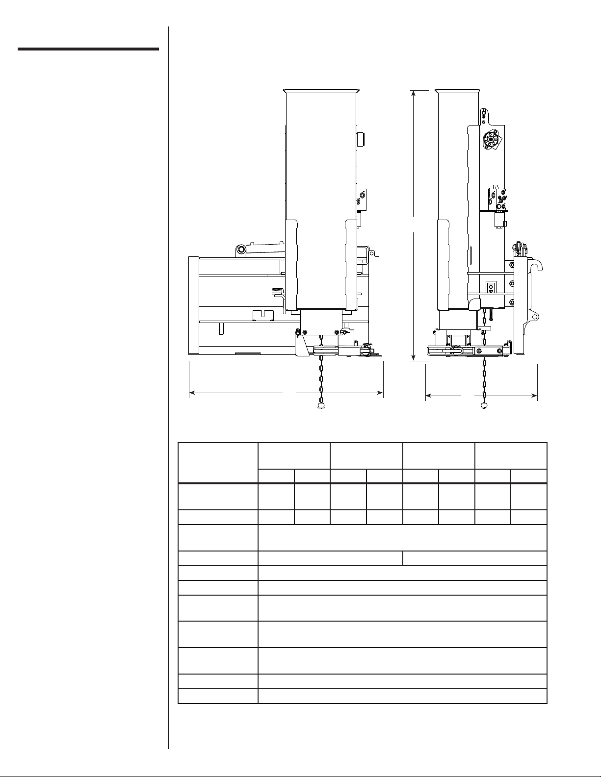
Specifications
C
A
Hammer w/ Grapple w/ Tilt
EM40 LM40 EM40 LM40 EM40 LM40 EM40 LM40
Overall Length
(A)
Overall Width (B) 27.5" 25" 27.5" 25" 27.5" 25.5" 27.5" 25.5"
Overall Height
(C)
Tilt (left or right) N/A 20°
Hammer Weight 300 lbs. (500 lbs. max.)
Length of Stroke 40"
Max. Strokes Per
Minute
Hydraulic
Requirements
Maximum
Post Size
Impact Force 82000 lbs. @ 500 lb. weight
Impact Energy 1025 ft.-lbs. @ 300 lb. weight; 1709 ft.-lbs. @ 500 lb. weight
46" 45.5" 46" 45.5" 46" 45.5" 46" 45.5"
64"
35
1500-3000 PSI
Up to 30 GPM
8.5" x 9.25"
B
w/ Tilt and
Grapple
6

Hydraulic
Filtration Requirements:
Requirements
• A filter of, at least, 25 micron filtration is required. A filter capable of 10 micron
filtration is preferred. The majority of paper type filters are 25 microns or better.
NOTE
• A low pressure type filter can be installed in the return line from the control valves to
• A high pressure type filter can be used between the pump and the control valves.
• If the source of the hydraulic power does not have a filter, it will be necessary to install
Pressure and Flow Requirements:
• The Hammer is designed to operate up to 30 GPM and 1500 – 3000 PSI.
The life of the hydraulic motor is almost entirely dependent upon cleanliness
of the oil. Instructions in your vehicle operator’s manual regarding filter and
oil changes should be carefully followed. Even small amounts of dirt in the
hydraulic oil can cause premature motor failure that is not covered by warranty.
the sump. A low pressure type filter can, also, be installed in the sump or pump intake
line, but must be sized large enough to avoid starving the pump.
one at some point in the system so, at least, part of the hydraulic oil is being filtered
whenever the system is operating. After a filter is installed and before attaching
the Hammer, the entire hydraulic system should be drained, filled with new oil, and
operated for 30 minutes or until the system is warm. During this run time, operate all
valves, cylinders, and hydraulic motors on the attachment.
Valve Requirements:
• The hydraulic system used to power the Hammer should be equipped with a four-way
valve large enough to carry full pump outlet without restricting flow and causing oil
heating.
• The four-way valve requires a relief valve which will open and relieve extreme
pressures between the Hammer and control valve, even when the control valve is in a
neutral position. This feature can be obtained by connecting two external relief valves
between the main lines running from the control valve to the Hammer in such a way
that high pressure in either line will be relieved to the other line.
Hydraulic Fluid Selection Requirements:
• Premium grade petroleum based fluids will provide the best performance.
• Fluids that contain anti-wear agents, rust inhibitors, anti-foaming agents, and oxidation
inhibitors are recommended.
• The viscosity of the fluid should never fall below 70 SUS (13 cST). The best
viscosity range of the Hammer is 100-200 SUS (20-43 cST).
7
WARNING
D A N G E R
WARNING
Assembly &
WARNING
Installation
Add Additional Weight
For tough driving conditions or large posts, additional weight can be added up to 500
lbs. total hammer weight by purchasing a weight kit or by adding weight. Add weight in
a variety of ways: logging chain, metal punch slugs, lead tire weights, etc. Do not use
concrete or sand, as damage may result.
Personal protection
equipment including hard
hat, safety glasses, safety
shoes, gloves, and ear
plugs are recommended
during assembly,
installation, operation,
maintenance, service,
removal, or movement of
the attachment.
STEP 1:
STEP 2:
STEP 3:
STEP 4:
STEP 5:
STEP 6:
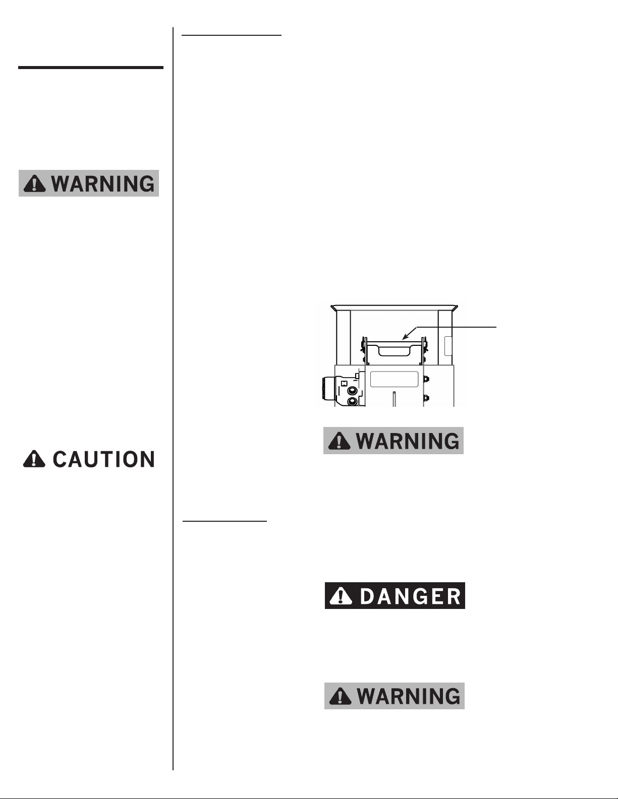
Make sure the hammer weight catch is visible through the viewing slots on the
back of the case.
Remove the retention pin from the top of the case. Insert a hook into the lifting
eye located on the top of the weight. Lift the weight out of the Hammer with a
hoist, forklift, or another vehicle. Set the weight on the ground.
Remove the weight cover by loosening the two lock nuts. It may be necessary to
use a hammer and punch in order to break the weight cover loose.
Place the additional weight into the cavity of the hammer weight until full.
Reinstall the weight cover using the two washers and lock nuts, making sure to
seal the cover with silicone sealant.
Lower the weight back into the Hammer and reinstall the retention pin.
Retention
Pin
Because of the weight
of some components,
and because some
components are difficult
to balance, two people are
required for safe
assembly and installation
of this equipment.
Do not tilt or operate the Hammer without the retention pin
in place. The hammer weight could slide out of the Hammer
and cause serious injury or death.
Prepare the Vehicle
Read and understand the manual for your vehicle before assembling or installing the
Hammer. The vehicle must be equipped with a universal quick attach hitch and auxiliary
hydraulics. The use of the Hammer may require the addition of counterweights to ensure
the attachment does not exceed the rated capacity of the vehicle.
Do not exceed the vehicle's rated operating load. If
necessary, use sufficient counterweights.
STEP 1:
Install the Hammer by following your vehicle operator's manual for installing an
attachment.
Make sure the Hammer is securely latched to the vehicle.
Failure to do so could result in separation of the attachment
from the vehicle.
8
Assembly &
WARNING
WARNING
WARNING
Installation
(continued)
Raise the Hammer slightly, and latch the parking stand into the upright position.STEP 2:
STEP 3:
STEP 4:
Route the hydraulic hoses through the quick attach plate hose holder, and connect
the hydraulic hoses to the vehicle's auxiliary hydraulics.
Remember hydraulic systems are under pressure whenever
the engine is running and may hold pressure after
shutdown. Before connecting or disconnecting hydraulic
hoses, be sure to relieve all pressure by cycling all
hydraulic controls after shutdown.
Ensure the retention pin is in place. The retention pin prevents the hammer weight
from sliding out of the Hammer.
Retention
Pin
STEP 5:
STEP 6:
STEP 7:
Do not tilt or operate the Hammer without the retention pin
in place. The hammer weight could slide out of the Hammer
and cause serious injury or death.
Shut off the vehicle engine.
Oil the Hammer drive chain, and grease all zerks.
Start the vehicle. Engage the auxiliary hydraulics. Note the direction of the chain
rotation (visible from the operator’s seat). The hammer weight catch should be
rotating from the top to the bottom. If the chain is not rotating at all, reverse the
hydraulic hoses.
Remember hydraulic systems are under pressure whenever
the engine is running and may hold pressure after
shutdown. Before connecting or disconnecting hydraulic
hoses, be sure to relieve all pressure by cycling all
hydraulic controls after shutdown.
9

Assembly &
NOTE
WARNING
Installation
STEP 8:
Check the hydraulic system for leaks.
(continued)
Never check pressurized system for leaks with your bare
hand. Wear proper hand and eye protection and use wood
or cardboard when searching for suspected leaks. Oil
escaping from pinhole leaks under pressure can penetrate
skin and create a serious medical emergency. If any fluid
is injected into the skin, gangrene, blood poisoning, even
death may result. Obtain medical attention immediately.
Tilt Option
If the Hammer is equipped with Tilt, follow the instructions below.
STEP 9:
STEP 10:
STEP 11:
STEP 12:
Grease the grease zerk on the tilt pivot boss.
Route the wires along the hydraulic hoses to the vehicle, and secure them with
zip-ties.
Route the control portion of the wiring harness along the loader arm of the vehicle
and into the cab, and secure the wiring with zip-ties. Mount the switch out of the
way of other controls.
Keep wiring a safe distance from hot components such as a heater or exhaust.
Connect the remainder of the wiring harness to a 12 volt power supply. If
necessary, consult your dealer.
10

D A N G E R
D A N G E R
D A N G E R
D A N G E R
D A N G E R
D A N G E R
NOTE
WARNING
Operation
Hammer
Before you operate the attachment, check over pins and
connections to be sure they all are securely in place. Make
sure the Hammer is securely latched to the vehicle.
Consult local utility companies to make certain there are
no buried gas lines, electrical cables, etc., in the work
area before beginning operation. Do not drive posts near
underground utility lines.
The Hammer is designed
to be operated from
the vehicle seat. Keep
bystanders away from the
work area. Do not operate
with another person in
contact with any part of
the Hammer.
Stay away from power
lines when transporting,
raising, or operating the
attachment.
STEP 1:
STEP 2:
STEP 3:
Without the Grapple, the Hammer requires a second person to position the post.
This person will set the post at the desired location and grasp the post securely,
making sure his hands are at least 30 inches (30") from the top of the post.
When using a second person, do not turn on the auxiliary
hydraulics until the second person is clear from the work
area.
After the post is in position, move the vehicle with the arms raised, and position
the Hammer directly over the top of the post.
Lower the Hammer onto the top of the post, ensuring the post is inside of the lower
portion of the Hammer. Continue lowering the Hammer until the oating anvil has
moved up and the weight of the Hammer is supported by the post.
After the post is in position, the second person must move
away from the Hammer and vehicle.
Personal protection
equipment including hard
hat, safety glasses, safety
shoes, gloves, and ear
plugs are recommended
during assembly,
installation, operation,
maintenance, service,
removal, or movement of
the attachment.
STEP 4:
STEP 5:
STEP 6:
STEP 7:
STEP 8:
After the second person has cleared the area, place the loader arms in the oat
position. If the vehicle is not equipped with oat, the loader arms should be
lowered, applying down force to the post.
Move the vehicle slowly left, right, forward, or backward as needed until the post
appears vertical to the ground.
The Hammer can now be activated by turning the auxiliary hydraulics to the
forward position. If you are not using the loader oat position, the loader arms
should be lowered as the post is driven into the ground.
Drive the post to the desired depth.
As soon as the weight is released (starts to drop), shut off the auxiliary hydraulics,
raise the Hammer until the post is cleared, and move to the next post.
When stopping the Hammer, the hammer weight catch should be visible through
the viewing slots on the back of the case. Never stop the Hammer with the
hammer weight partially raised.
11

Operation
D A N G E R
D A N G E R
D A N G E R
D A N G E R
NOTE
WARNING
Hammer w/ Grapple
The Hammer is designed
to be operated from
the vehicle seat. Keep
bystanders away from the
work area. Do not operate
with another person in
contact with any part of
the Hammer.
STEP 1:
STEP 2:
STEP 3:
STEP 4:
STEP 5:
Before you operate the attachment, check over pins and
connections to be sure they all are securely in place. Make
sure the Hammer is securely latched to the vehicle.
Consult local utility companies to make certain there are
no buried gas lines, electrical cables, etc., in the work
area before beginning operation. Do not drive posts near
underground utility lines.
Raise the Hammer approximately two feet (2') off the ground with the Hammer
tilted slightly forward so the grapple jaws are visible.
Drive the vehicle forward and position the grapple jaws around the post,
approximately four inches (4") from the top of the post.
Activate the auxiliary hydraulics in the reverse direction for two (2) seconds or
until the grapple jaws are rmly clamped around post.
Raise the loader arms until the bottom of the post is above the ground.
Position the post in desired location and lower the Hammer until the post is inside
the lower portion of the Hammer.
Stay away from power
lines when transporting,
raising, or operating the
attachment.
Personal protection
equipment including hard
hat, safety glasses, safety
shoes, gloves, and ear
plugs are recommended
during assembly,
installation, operation,
maintenance, service,
removal, or movement of
the attachment.
STEP 6:
STEP 7:
STEP 8:
STEP 9:
STEP 10 :
STEP 11:
STEP 12:
Intermittently activate auxiliary hydraulics in the forward direction to release the
grapple jaws from the post. The Grapple will rotate up and away from the post.
Continue lowering the Hammer until the oating anvil has moved up and the
weight of the Hammer is supported by the post.
Place the loader arms in the oat position. If the vehicle is not equipped with
oat, the loader arms should be lowered, applying down force to the post.
Move the vehicle slowly left, right, forward, or backward as needed until the post
appears vertical to the ground.
The Hammer can now be activated by turning the auxiliary hydraulics to the
forward position. If you are not using the loader oat position, the loader arms
should be lowered as the post is driven into the ground.
Drive the post to the desired depth.
As soon as the weight is released (starts to drop), shut off the auxiliary hydraulics,
raise the Hammer until the post is cleared, and move to the next post.
When stopping the Hammer, the hammer weight catch should be visible through
the viewing slots on the back of the case. Never stop the Hammer with the
hammer weight partially raised.
12

Operation
D A N G E R
D A N G E R
D A N G E R
D A N G E R
WARNING
Hammer w/ Tilt
and Grapple
The Hammer is designed
to be operated from
the vehicle seat. Keep
bystanders away from the
work area. Do not operate
with another person in
contact with any part of
the Hammer.
Before you operate the attachment, check over pins and
connections to be sure they all are securely in place. Make
sure the Hammer is securely latched to the vehicle.
Consult local utility companies to make certain there are
no buried gas lines, electrical cables, etc., in the work
area before beginning operation. Do not drive posts near
underground utility lines.
Remove the tilt lock pin.STEP 1:
Tilt Lock Pin
Stay away from power
lines when transporting,
raising, or operating the
attachment.
Personal protection
equipment including hard
hat, safety glasses, safety
shoes, gloves, and ear
plugs are recommended
during assembly,
installation, operation,
maintenance, service,
removal, or movement of
the attachment.
STEP 2:
STEP 3:
STEP 4:
STEP 5:
STEP 6:
STEP 7:
STEP 8:
STEP 9:
STEP 10:
LM40 (shown)
Raise the Hammer approximately two feet (2') off the ground with the Hammer
tilted slightly forward so the grapple jaws are visible.
Drive the vehicle forward and position the grapple jaws around the post,
approximately four inches (4") from the top of the post.
Activate the auxiliary hydraulics in the reverse direction for two (2) seconds or
until the grapple jaws are rmly clamped around post.
Raise the loader arms until the bottom of the post is above the ground.
Position the post in desired location and lower the Hammer until the post is inside
the lower portion of the Hammer.
Intermittently activate auxiliary hydraulics in the forward direction to release the
grapple jaws from the post. The Grapple will rotate up and away from the post.
Continue lowering the Hammer until the oating anvil has moved up and the
weight of the Hammer is supported by the post.
Place the loader arms in the oat position. If the vehicle is not equipped with
oat, the loader arms should be lowered, applying down force to the post.
Move the vehicle slowly left, right, forward, or backward as needed until the post
appears vertical to the ground.
STEP 11:
STEP 12:
Activate the electrical control switch.
Tilt the Hammer to a vertical position. Activate the auxiliary hydraulics to tilt the
Hammer clockwise up to 20 degrees (20°). Activating the auxiliary hydraulics in
reverse will tilt the Hammer counter-clockwise up to 20 degrees (20°).
13

D A N G E R
WARNING
D A N G E R
NOTE
Operation
WARNING
STEP 13:
Deactivate the electrical control switch.
(continued)
Removal &
Storage
STEP 14:
STEP 15:
STEP 16:
The Hammer can now be activated by turning the auxiliary hydraulics to the
forward position. If you are not using the loader oat position, the loader arms
should be lowered as the post is driven into the ground.
Drive the post to the desired depth.
As soon as the weight is released (starts to drop), shut off the auxiliary hydraulics,
raise the Hammer until the post is cleared, and move to the next post.
When stopping the Hammer, the hammer weight catch should be visible through
the viewing slots on the back of the case. Never stop the Hammer with the
hammer weight partially raised.
Before disconnecting the Hammer from the vehicle, tilt to a
vertical position and reinstall the tilt lock pin. Failure to do
so will cause the Hammer to become unstable in the freestanding position.
Before storage, the Hammer should be thoroughly cleaned, washing off all dirt and grime.
If you have a Grapple or Tilt, coat the exposed portions of the cylinder rod with grease.
Lubricate the drive chain, and grease all zerks. Make sure the hydraulic system is properly
sealed against contaminates entering the unit. Always store the Hammer in a dry, covered
location.
Personal protection
equipment including hard
hat, safety glasses, safety
shoes, gloves, and ear
plugs are recommended
during assembly,
installation, operation,
maintenance, service,
removal, or movement of
the attachment.
STEP 1: Lower the parking stand by pulling up on the lock pin.
STEP 2: Lower the Hammer onto a at, level surface. If the Hammer is equipped with a
Grapple, lower the Hammer until the end of the Grapple jaws touch the ground.
Shift the vehicle to the left while lowering the Hammer in order to rotate the
Grapple to the horizontal position.
NOTE
Always store the Hammer with the Grapple horizontal.
Never allow anyone under the attachment at any time.
STEP 3: Shut off the vehicle engine, lower the arms, relieve all hydraulic pressure (by
activating the vehicle controls), and remove the vehicle key before leaving the
vehicle seat.
Before disconnecting hydraulic lines or fittings be sure
to relieve all pressure by cycling all hydraulic controls
after shutdown. Remember hydraulic systems are under
pressure whenever the engine is running and may hold
pressure after shutdown.
14
STEP 4: Disconnect the hydraulic hoses from the vehicle's auxiliary hydraulics.
NOTE
STEP 5: Follow your vehicle operator's manual for removing an attachment.
Connect the quick couplers together to prevent contaminants from entering the
Hammer hydraulic system.

Troubleshooting
PROBLEM POSSIBLE CAUSE SOLUTION
Floating anvil falls out
or gets jammed
a. Weight is not down after
driving
b. Post too small Use T-post adapter when driving
When nished driving, make sure
weight is down and/or catch is visible
through viewing slots. Refer to
Operation section of manual.
small posts.
Weight is dropping
unexpectedly
Vehicle battery is dead a. Tilt switch was activated
Weight not cycling a. No post loaded in
Motor will not operate a. Motor damaged Contact Danuser.
Chain jumps a. Incorrect chain tension Adjust chain tension.
a. Weight is not down after
driving
too long
Hammer
b. Broken or missing shaft
key
c. Channel is not lubricated Grease the inside of the Hammer case.
d. Motor damaged Contact Danuser.
b. Incorrect hose routing Refer to Hydraulics section of manual
b. Sprockets or chain are
worn
When nished driving, make sure
weight is down and/or catch is visible
through viewing slots. Refer to
Operation section of manual.
Deactivate tilt switch when Hammer
is not in use.
A post must be pushed up inside the
Hammer until it stops before the
weight will cycle.
Replace key.
for proper hose routing.
Replace worn item(s).
Oil over heating a. High ow activated Ensure vehicle is not in high ow
mode.
b. Low oil level Fill reservoir to proper level.
c. Dirty oil or oil lter Change oil and lter.
Tilt feature not
working
Tilt or grapple
cylinder not working
For additional assistance, please call your dealer or contact Danuser direct:
a. No power to solenoid Check electrical connections. Ensure
switch is activated.
b. Blown fuse Check inline fuse in electrical
harness. Check vehicle's fuses.
c. Solenoid not working Contact Danuser.
d. Tilt lock pin in place Remove tilt lock pin. Refer to
Operation section of manual.
a. Air in hydraulic system Cycle hydraulics until both cylinders
have completely extended and
retracted (fully cycled).
b. Incorrect hose routing Refer to Hydraulics section of manual
for proper hose routing.
c. Tilt or Grapple
obstruction
d. Cylinder damaged Contact Danuser.
Phone: (573) 642-2246
Fax: (573) 642-2240
E-mail: sales@danuser.com
Ensure tilt and grapple mechanisms
can move freely.
15

Maintenance
WARNING
Personal protection
equipment including hard
hat, safety glasses, safety
shoes, gloves, and ear
plugs are recommended
during assembly,
installation, operation,
maintenance, service,
removal, or movement of
the attachment.
DAILY
CHECK FOR CLEAN HYDRAULIC OIL
The majority of all hydraulic component failures are caused by contamination of the
hydraulic oil. At all times, keep dirt and other contaminates from entering the hydraulic
system during connecting and disconnecting the hydraulic system. Always use dust caps
and plugs on all quick disconnects when not in use.
CHECK ALL HYDRAULIC HOSE ASSEMBLIES
Check for cracked or brittle hoses. Replace hoses immediately if cracked or brittle.
Replacement of hoses before failure will prevent loss of hydraulic oil, hydraulic oil
contamination, and component damage caused by cavitation.
CHECK ATTACHMENT AND ALL ACCESSORIES
Check all bolts and fasteners for tightness. Visually inspect the attachment for damage.
EVERY 40 HOURS
GREASE ZERKS
Grease the zerk on the drive chain bearing. Grease the zerk on the bottom chain sprocket
shaft. If equipped with Tilt, grease the zerk on the tilt pivot boss.
LUBRICATE ATTACHMENT
Grease the inside of the Hammer case. Lubricate the drive chain with a high quality
commercial grade chain lubricant.
CHECK ATTACHMENT AND ACCESSORIES
Visually inspect all welds for cracks. Check the chain catch for wear. Check all bolts and
fasteners for tightness.
CHECK CHAIN TENSION
Inspect the chain tensioning springs. Springs should be preloaded but not entirely collapsed.
16

Service
D A N G E R
WARNING
NOTE
WARNING
Never attempt repairs or adjustments while the equipment
is in operation.
Replacing the Drive Chain
STEP 1:
Make sure the hammer weight catch is visible through the viewing slots on the
back of the case.
Personal protection
equipment including hard
hat, safety glasses, safety
shoes, gloves, and ear
plugs are recommended
during assembly,
installation, operation,
maintenance, service,
removal, or movement of
the attachment.
Because of the weight
of some components,
and because some
components are difficult
to balance, two people are
required for servicing of
this equipment.
STEP 2:
STEP 3:
STEP 4:
STEP 5:
STEP 6:
STEP 7:
STEP 8:
STEP 9:
STEP 10:
Remove the retention pin from the top of the case. Insert a hook into the lifting
eye located on the top of the weight. Lift the weight out of the Hammer with a
hoist, forklift, or another vehicle. Set the weight on the ground.
Carefully lay down the Hammer on its front side.
Remove the top and bottom chain covers.
Remove the retaining ring fastened to the lower sprocket shaft assembly, and pull
out the shaft from the opposite side of the Hammer.
Remove the tensioning rods and shim(s). Slide chain slack to the top of the
Hammer.
Find the chain catch and two pins that secure it. Remove the clips that retain the
pins, and remove the pins.
Install new chains over the upper sprocket shaft assembly. Make sure open ends
of the chain are at equal links away from sprockets.
Reinstall the chain catch and pins through the open ends of the new chain. Install
clips on the pins.
Slide chain slack to the bottom of the Hammer, and insert the lower sprocket shaft
assembly into the chain.
1.5"
Tighten tensioning nuts until
springs are adequately preloaded
STEP 11
STEP 12:
STEP 13:
STEP 14:
Shim(s) must be inserted between the tensioning rods and the lower sprocket shaft
assembly to maintain proper sprocket location.
Insert the lower sprocket shaft through the side of the Hammer and through the
tensioning rods and sprockets.
Install shim(s) and retaining ring on the end of the sprocket shaft.
Install bottom chain guard and tensioning springs. Tighten tensioning nuts until
the springs are adequately preloaded but not entirely collapsed.
Install the top chain cover, stand Hammer upright, reinstall weight, and install the
retention pin.
Do not tilt or operate the Hammer without the retention pin
in place. The hammer weight could slide out of the Hammer
and cause serious injury or death.
17

Parts
= Safety Sign
Location
7
8
28
26
25
19
27
24
1
23
2
22
3
18
21
20
30
4
31
17
5
18
29
10
14
13
16
15
6
12
11
9

Parts
REF. NO. PART NO. DESCRIPTION QTY.
(continued)
1 10195 Toplock Nut (1/4" 20) 4
2 21056 1/4" Flat Washer 4
3 21055 Bolt (1/4" 20 x 1") 4
4 21214 Hydraulic Manifold 1
5 21169 Foot 1
6 21079 Pin 1
7 10268 Toplock Nut (3/4" 10) 8
8 10267 3/4" Flat Washer 8
9 21062 Grapple Assembly 1
10 21148 Grapple Spring 1
11 21124 Floating Anvil 1
12 6156 Socket Head Bolt (1/2" 13 x 1-1/2") 4
13 21156 1/2" Flat Washer 8
14 10125 Toplock Nut (1/2" 13) 4
15 21105 Bolt (3/4" 10 x 2-1/4", Gr. 5) 6
16 21180 Euro/Global Quick Attach Plate 1
17 21179 Offset Skid-Steer Quick Attach Plate 1
18 21202 Euro/Global Quick Attach Plate w/ Tilt 2
19 21178 Offset Skid-Steer Quick Attach Plate w/ Tilt 2
20 21243 Bolt (3/8" 16 x 3/4") 3
21 21133 Cover 1
22 21118 Retention Pin 1
23 21078 Rue Clip 6
24 21045 Weight 1
25 21051 Cover 1
26 21054 Stud (3/4" 10 x 3-1/4") 2
27 21044 Weight Assembly (consists of items 7, 8,
24, 25, and 26)
1
28 21207 Pin 1
29 21208 Parking Stand 1
30 21206 Pin 1
31 2164 Drive Screw 1
19

Parts
REF.
NO.
PART
NO.
DESCRIPTION
QTY.
Drive Assembly
1 21119 Connecting Link 2
3
2
1
4
9
8
6
5
7
10
11
12
13
14
2 21024 Chain Pin 2
3 21025 Roller Chain #80, 1" Pitch 2
4 21122 Catch Weight 1
5 21126 Socket Head Bolt
(1/2" 13 x 2")
6 21113 Hydraulic Motor 1
7 21114 Upper Sprocket Shaft
Assembly
8 21136 1" Shim 1
9 21156 1/2" Flat Washer 2
10 21043 Bearing 1
11 2489 7/16" Flat Washer 4
12 10197 Toplock Nut (7/16" 14) 4
13 21057 Bolt (7/16" 14 x 1-1/2") 4
14 10125 Toplock Nut (1/2" 13) 2
15 21040 Sprocket Shaft 1
16 21080 Lower Sprocket Shaft
Assembly
17 21125 Shim 2
18 21083 Tensioning Rod 2
19 10267 3/4" Flat Washer 1
20 2172 Retaining Ring 1
21 21123 Spring 2
22 2178 3/8" Flat Washer 2
23 10412 Toplock Nut (3/8" 16) 2
24 21110 Cover Assembly 1
2
1
1
20
15
16
21
22
23
24
17
18
19
20
= Safety Sign
Location

Parts
Hydraulics
= Safety Sign
Location
3
4
1
5
6
2
REF. NO. PART NO. DESCRIPTION QTY.
1 21139 Vehicle-Manifold Hydraulic Hose 2
2 10048 Male Coupler 1
3 10049 Female Coupler 1
4 21141 #6 O-ring Plug 4
5 21233 Motor-Manifold Hydraulic Hose 2
6 21216 Solenoid Plug 1
21

Parts
Tilt Hydraulics
= Safety Sign
Location
1
2
5
REF. NO. PART NO. DESCRIPTION QTY.
1 21238 Manifold-Cylinder Hydraulic Hose 1
2 21235 Manifold-Cylinder Hydraulic Hose 1
3 21225 #6 O-ring 1/4" Pipe Elbow 3
4 21226 Hydraulic Cylinder 1
5 21215 Solenoid Valve 1
3
4
22

Parts
Grapple Hydraulics
= Safety Sign
Location
1
2
3
REF. NO. PART NO. DESCRIPTION QTY.
1 21225 #6 O-ring 1/4" Pipe Elbow 2
2 21234 Manifold-Grapple Hydraulic Hose 1
3 21235 Manifold-Grapple Hydraulic Hose 1
23

Parts
Grapple
= Safety Sign
Location
7
1
5
3
4
2
6
REF. NO. PART NO. DESCRIPTION QTY.
1 21063 Case 1
2 21070 Right Jaw 1
3 21073 Left Jaw 1
4 21077 Clevis Pin 3
5 21078 Rue Clip 4
6 21134 Clevis Pin 1
7 21167 Hydraulic Cylinder 1
24

Parts
4
5
EM40 Tilt
= Safety Sign
Location
11
1
2
3
6
7
8
9
10
13
12
REF. NO. PART NO. DESCRIPTION QTY.
1 10268 Toplock Nut (3/4" 10) 2
2 21106 Bolt (3/4" 10 x 2-3/4") 2
3 10267 3/4" Flat Washer 2
4 21134 Clevis Pin 1
5 21078 Rue Clip 1
6 21200 Euro/Global Tilt Bracket 1
7 21107 5/8" Large Flat Washer 4
8 21108 Flange Bolt (5/8" 11 x 1-1/4", Gr. 8) 4
9 21226 Hydraulic Cylinder 2
10 21189 Euro Quick Attach Plate 4
11 21220 Wiring Harness 8-Pin 1
21221 Wiring Harness 14-Pin
21222 Wiring Harness 14-Pin Deere
12 21223 Cigarette Lighter Adapter 1
13 21162 Wiring Harness 1
25

Parts
4
5
LM40 Tilt
= Safety Sign
Location
11
1
2
3
6
7
8
9
10
13
12
26
REF. NO. PART NO. DESCRIPTION QTY.
1 10268 Toplock Nut (3/4" 10) 2
2 21106 Bolt (3/4" 10 x 2-3/4") 2
3 10267 3/4" Flat Washer 2
4 21134 Clevis Pin 1
5 21078 Rue Clip 1
6 21176 Offset Skid-Steer Tilt Bracket 1
7 21107 5/8" Large Flat Washer 4
8 21108 Flange Bolt (5/8" 11 x 1-1/4", Gr. 8) 4
9 21226 Hydraulic Cylinder 2
10 21173 Offset Skid-Steer Quick Attach Plate 4
11 21220 Wiring Harness 8-Pin 1
21221 Wiring Harness 14-Pin
21222 Wiring Harness 14-Pin Deere
12 21223 Cigarette Lighter Adapter 1
13 21162 Wiring Harness 1

Decals &
WARNING
Safety Signs
PART NO. DIG21
Location: Unit, left side
(5 7 3) 642 -22 4 6 www.danuser.com
PART NO.
DANUSER101
Location: Unit, front
PART NO. DIG13
Location: Unit, left side
PART NO. DIG16
Location: Unit, left side
PART NO. 9875
Location:
Drive Unit, front
HAMMER
DECAL
Location: Unit,
front
MODEL
DECAL
Location:
Unit, front
PART NO. DIG14
Location: Unit, left side
Clean or replace all safety
signs if they cannot be
clearly read and understood.
PART NO. DIG26
Location: Grapple,
top & bottom
27

Decals &
WARNING
Safety Signs
(continued)
Model No. & Serial No.
Location: Unit, rear
PART NO. DIG22
Location: Unit, rear shelf
PART NO. DIG23
Location: Unit, rear
PART NO. DIG5
Location:
Unit, right side
PART NO. PHDC6
Location: Unit, inside rear
PART NO. DIG24
Location: Unit, rear
Clean or replace all safety
signs if they cannot be
clearly read and understood.
28
PART NO. DIG25
Location: Tilt plate
Offset Skid-Steer
Quick Attach Plate
(shown left)

Accessories
Wiring Harness Options
PN 21220 - 8 Pin
PN 21221 - 14 Pin
PN 21222 - 14 Pin Deere
PN 21223 - Cigarette Lighter Adapter
T-Post Adapter
PN 21149
Additional Weight Kit (not shown)
PN 21163
Front-End Loader Hose Kit (not shown)
PN 21231
29

Warranty
DANUSER
Model #
LIMITED WARRANTY
Danuser LLC (“Danuser”) warrants its products, under normal use and maintenance, to be free from defects in material and
workmanship for periods specified below from the purchase date from an authorized Danuser Dealer. Start of the warranty period
is determined by purchase date given on your returned WARRANTY REGISTRATION FORM. Proof of purchase may be required.
This Limited Warranty is extended only to the original purchaser of Danuser products.
Hammer - 1 Year
1. During the applicable warranty period, Danuser, at its option, will repair or replace any part determined by Danuser to be
defective. Such repair or replacement shall take place at Danuser’s factory or a location designated by Danuser. Under no
circumstances shall Danuser be obligated for the cost of any repair or replacement by anyone other than Danuser without its
express written consent.
2. Parts may not be returned without written authorization from Danuser.
3. Some purchased components, including but not limited to hydraulic components are subject to the inspection and warranty of
the respective manufacturer. Thus, delays in a warranty determination can be expected while Danuser awaits their decision.
4. This warranty is void if any attempt is made to make field repairs to hydraulic components. To qualify for warranty inspection,
the “failed” part must be returned in its original “failed” condition.
5. To make a claim under this warranty, first contact your authorized Danuser Dealer. The Danuser Dealer shall complete the
Warranty Claim Form and obtain written authorization from Danuser to return parts. All warranty claims must include
detailed information regarding make and model of vehicle on which the Danuser product was mounted, hours of use,
description of events that led up to the failure, and any other information helpful in reviewing the warranty claim. All
warranty returns must be prepaid. Shipments arriving at our factory on a freight collect basis will be refused by our receiving
department. The freight charge will be credited if the parts are determined by Danuser to be defective, and the associated
freight costs in returning those parts will be prepaid by Danuser. NOTE: Hydraulic motors must arrive with all ports sealed
from dirt and moisture. If a motor arrives with open ports, the warranty is void and no inspection will be made.
Serial #
6. Products or parts thereof which, as determined by Danuser’s examination, show wear from normal use, have been improperly
operated, damaged by accident or negligence, field repaired, altered or modified are not considered defective in material and
workmanship and are not covered by this warranty. This warranty does not apply to parts subject to normal wear or to damage
caused by the failure to perform recommended maintenance or to replace worn parts. This warranty shall not obligate Danuser
to bear any cost of labor for field repair, replacement, testing, or adjustment nor for damage caused by accident, abuse, misuse,
or environmental elements.
7. Any parts or labor required to repair or replace parts not covered under this warranty will be charged to the customer. Parts
repaired or replaced by Danuser are then covered by this warranty only for the remainder of the original warranty as if such
parts were original parts.
8. Danuser reserves the right to change its specifications and designs at any time.
This warranty is exclusive and in lieu of all other express warranties, if any, including the implied warranties of merchantability and
fitness for a particular purpose. It shall not extend beyond the duration of the expressed warranty provided herein and the remedy
for violations of any implied warranty shall be limited to repair or replacement of the defective part pursuant to the terms contained
herein. No employee, dealer, salesman, or representative is authorized to change this warranty in any way or grant any other
warranty. Danuser shall not be liable for any consequential, incidental, or punitive damages, losses, or expenses, including those
resulting from or caused by any defects.
Danuser LLC Tel: (573) 642-2246
500 E. 3rd St. Fax: (573) 642-2240
P.O. Box 368 E-mail: sales@danuser.com
Fulton, MO 65251 Website: www.danuser.com
Form No. 3269
 Loading...