

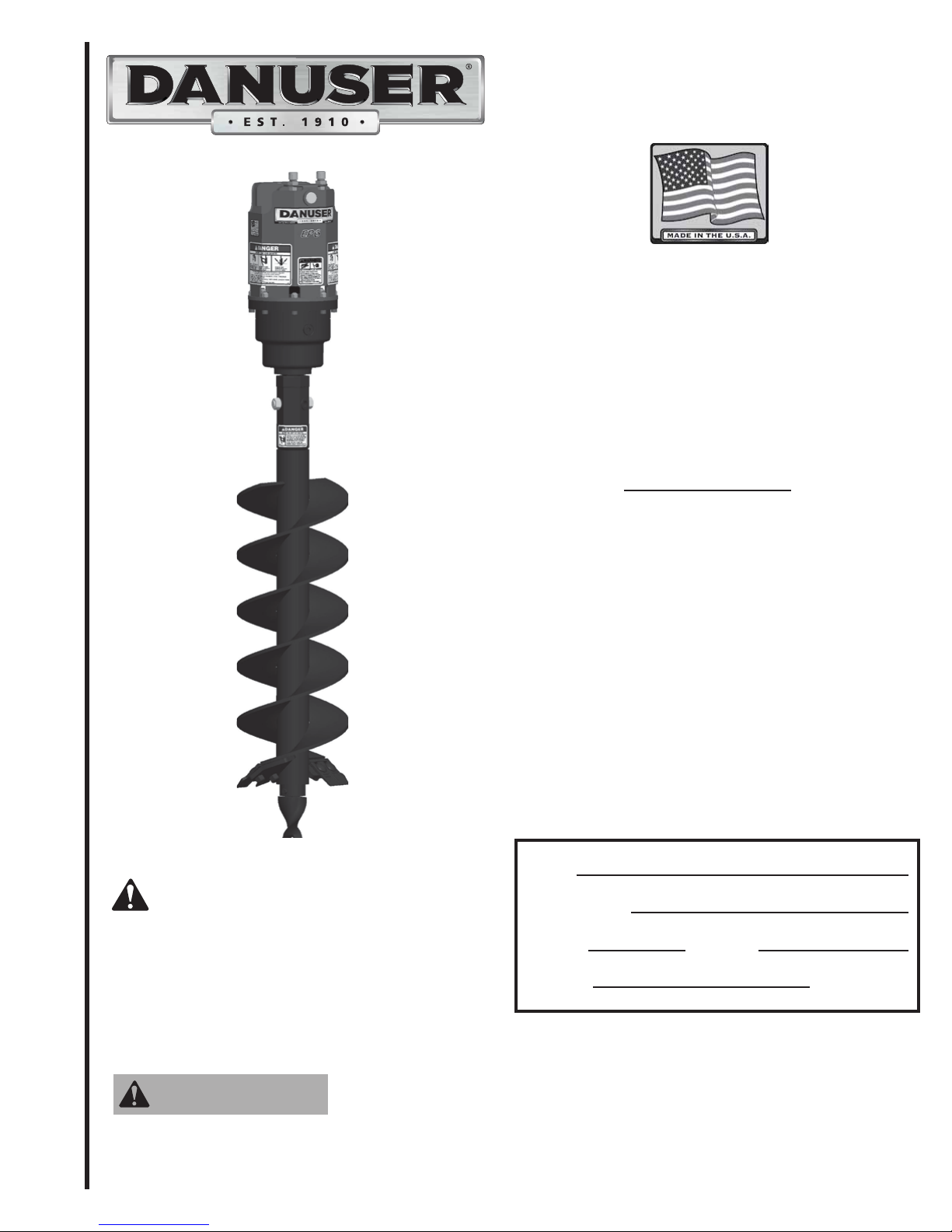
EP
HEAVY DUTY
AUGER SERIES
MODELS
Read this entire manual. This
safety alert symbol is used
throughout this manual to call your
attention to messages involving
your personal safety and the safety
of others. Failure to follow these
instructions can result in injury or
death.
WARNING
Si no entiende ingles, se prefiere que
busque a alguien que interprete las
instrucciones para usted.
EP6 Hex,
EP10 Hex,
EP15 Hex,
EP20 Hex,
Owner:
Date Purchased:
Model #: Serial #:
Manual #:
9MEP2457351
EP6 Round
EP10 Round
EP15 Round
EP20 Round
Operator’s Manual
Danuser LLC
500 E. 3rd St.
P.O. Box 368
Tel: (573) 642-2246 Fax: (573) 642-2240
Fulton, MO 65251
E-mail: sales@danuser.com
Website: www.danuser.com

Dear Owner/Operator,
Thank you for purchasing this Danuser Hydraulic Earth Auger. We appreciate your business.
The EP heavy-duty auger series is designed to meet the needs of farmers, ranchers, contractors,
landscapers, and municipalities. Various auger styles are available for drilling in light ground
conditions to harder ground conditions, such as rock, frozen ground, and more.
Your safety as an operator of our product is very important to us. Therefore, before you assemble,
install, operate, maintain, service, remove, or move your Danuser Earth Auger, read and understand
this manual thoroughly. If there is anything you do not understand, immediately contact your
dealer, or contact our factory direct.
Phone: (573) 642-2246
Fax: (573) 642-2240
E-mail: sales@danuser.com
Your satisfaction in the performance and longevity of our product is also very important to us and
can be prolonged by proper assembly, installation, operation, and maintenance as instructed in this
manual.
Thank you again for your business and for your trust in our product. Please feel free to contact us
at any time for further assistance.
Sincerely,
Danuser LLC
500 E. 3rd St.
P.O. Box 368
Fulton, MO 65251
Tel: (573) 642-2246 Fax: (573) 642-2240
E-mail: sales@danuser.com Website: www.danuser.com
Danuser provides this manual "as is" without warranty of any kind, either expressed or implied. Danuser assumes
no responsibility for errors or omissions. Danuser assumes no liability for damages resulting from the use of the
LQIRUPDWLRQFRQWDLQHGKHUHLQ'DQXVHUUHVHUYHVWKHULJKWWRUHYLVHDQGLPSURYHLWVSURGXFWVDVLWVHHV¿W7KLVPDQXDO
GHVFULEHVWKHVWDWHRIWKLVSURGXFWDWWKHWLPHRILWVSXEOLFDWLRQDQGPD\QRWUHÀHFWWKHSURGXFWLQWKHIXWXUH
Danuser is a registered trademark.
Foreword
Please read this manual thoroughly!
Before you assemble, install, operate, maintain, service, remove, or move your Danuser
Earth Auger, read this manual thoroughly. If there is anything you do not understand,
immediately contact your dealer, or call our factory direct at (573) 642-2246. Powered
equipment can be dangerous if not assembled, installed, operated, maintained, serviced,
removed, or moved properly.
Warranty Registration
To activate your warranty coverage and to provide you with efficient customer service,
please fill out your WARRANTY REGISTRATION FORM. This form is included in your
unit’s paperwork package. If you did not complete a WARRANTY REGISTRATION
FORM or did not receive one, please call Danuser LLC. Or, register online at
www.Danuser.com. Your satisfaction with our product and your safety as a user of our
product are both very important to us.
Symbols
This SAFETY ALERT symbol identifies important safety messages. Carefully read
each safety message that follows. Failure to understand and obey a safety message,
or recognize a safety hazard, could result in injury or death to you or others around you.
The operator is ultimately responsible for the safety of himself, as well as others, in the
operating area of the earth auger.
Symbol
DANGER
WARNING
CAUTION
Indicates an imminently hazardous situation which, if
not avoided, will result in death or serious injury.
Indicates a potentially hazardous situation which, if
not avoided, could result in death or serious injury,
including hazards that are exposed when guards are
removed.
Indicates a potentially hazardous situation which, if
not avoided, may result in minor or moderate injury.
It may also be used to alert against unsafe practices.
This is important information for proper use of this
equipment. Failure to comply may lead to premature
equipment failure.
Meaning
Table of
Contents
Page
Letter to the Owner/Operator ............................................ 2
Foreword ............................................................ 3
Symbols . . . . . . . . . . . . . . . . . . . . . . . . . . . . . . . . . . . . . . . . . . . . . . . . . . . . . . . . . . . . .3
Safety............................................................... 4
Decals & Safety Signs.................................................. 7
Drive Unit Specifications ............................................... 9
Hydraulic Requirements ................................................ 10
Assembly & Installation ................................................ 11
Operation ............................................................ 19
Removal & Storage .................................................... 21
Troubleshooting....................................................... 22
Maintenance & Lubrication.............................................. 23
Torque Values Chart.................................................... 24
Drive Unit Parts....................................................... 25
Augers & Accessories .................................................. 26
Warranty................................................... Form No. 3387
3

Safety
WARNING
Working with unfamiliar equipment can lead to careless injuries. Read and understand this manual and
the manual for your vehicle before assembling, installing, operating, maintaining, servicing, removing, or
moving this earth auger. If there is anything in this manual you do not understand, contact your dealer or
Danuser LLC. The safe use of this machine is strictly up to you, the operator. If this unit is used, loaned,
or rented by any other person, it is the owner's responsibility to make certain that the operator prior to
operating:
• Reads and understands the Operator's Manuals
• Is instructed in safe and proper use
There is an entanglement risk if you replace the special auger retaining bolt with a bolt longer than
specified by Danuser LLC. This improper replacement occurs most often on machines that are loaned or
rented to someone who has not read the Operator's Manual and is not familiar with an earth auger.
• This earth auger is designed for one-man operation from the vehicle seat. It is the responsibility of
the operator to see that no one is within twenty-five feet (25') of the earth auger when it is started or
in use. Do not operate the earth auger with another person near or in contact with any part of the
drive unit or auger. Serious personal injury or death may result if any attempt is made to assist
drilling operation by hand.
• All operators of this attachment must read and understand this entire manual, paying particular
attention to safety messages and operation instructions, prior to assembling, installing, operating,
maintaining, servicing, removing, or moving the earth auger.
• Please remember it is also important that you read, understand, and follow the safety signs on the
attachment. Clean or replace all safety signs if they cannot be clearly read and understood. They are
there for your safety as well as the safety of others. Danuser LLC will furnish new safety signs upon
request at no charge.
• All things with moving parts are potentially hazardous. There is no substitute for a cautious,
safe-minded operator who recognizes potential hazards and follows reasonable safety practices.
• Personal protection equipment including hard hat, safety glasses, safety shoes, and gloves are
recommended during assembly, installation, operation, maintenance, service, removal, or movement
of the attachment.
• When the use of hand tools is required to perform any part of assembly, installation, maintenance,
service, removal, or movement of the earth auger, be sure the tools used are designed and
recommended by the tool manufacturer for that specific task.
• Never check pressurized system for leaks with your bare hand. Wear proper hand and eye protection
and use wood or cardboard when searching for suspected leaks. Oil escaping from pinhole leaks
under pressure can penetrate skin and create a serious medical emergency. If any fluid is injected into
the skin, gangrene, blood poisoning, even death may result. Obtain medical attention immediately.
• Always use two people to handle heavy, unwieldy components during assembly, installation,
maintenance, service, removal, or movement of the attachment.
• Never place any part of your body where it would be in danger if movement should occur during
assembly, installation, operation, maintenance, service, removal, or movement of the earth auger.
• Check clearances between vehicle and auger, as well as operator and auger, across the full range of
loader arms’ operating heights. Keep earth auger in cradle when not drilling.
• Only properly trained people should operate this equipment. Do not allow anyone who has not read
this entire manual and understood the safety rules, safety signs, and operation instructions to use this
attachment.
4
• Never allow children to operate or be around this earth auger.

Safety
(continued)
• Do not allow riders on the equipment at any time. There is no safe place for any riders.
• Never use alcoholic beverages or drugs which can hinder alertness or coordination while operating
this equipment. Consult your doctor about operating this equipment while taking prescription
or over-the-counter medications.
• Safe operation of equipment requires the operator's full attention. Avoid distractions such as radio
headphones, cell phones, etc. while operating.
• Contact with underground gas lines or electrical cables may result in serious injury or death from
explosion or electrical shock. Before operating, call 811 or the local number to locate underground
utilities.
• Do not drill near underground utility lines.
• Before beginning operation, clear the work area of objects which might be picked up and thrown by
or entangled in the auger.
• The earth auger must be securely latched to the vehicle. Ensure both locking handles are in the
locked position with pins fully seated. An improperly latched earth auger can fall without warning.
• Before you operate the attachment, check over all pins, bolts, and connections to be sure all are
securely in place. Replace any damaged or worn parts immediately.
• Never replace the auger retaining bolt with anything other than the specified length bolt in this
manual. A longer, or protruding, fastener is more likely to grab clothing or gloves, which can result
in serious injury or death.
• Keep all helpers and bystanders twenty-five feet (25') away from an operating earth auger.
• Keep hands, feet, hair, jewelry, and clothing away from all moving and/or rotating parts.
• Never place yourself between the vehicle and the attachment.
• Worn teeth or a slightly rounded point can seriously affect auger penetration. Check for wear before
each use, and replace as necessary.
• Never position the auger point by hand or with any tool when the vehicle is running.
• Never position the auger point by putting your hands on the auger or drive unit.
• Do not shovel dirt away from a rotating auger, as the shovel can be caught and thrown by the auger.
• Never transport with the drive unit out of the cradle or while the auger is rotating.
• A heavy load can cause instability of the vehicle. Use extreme care during travel. Slow down on
turns and watch out for bumps. Use all safety devices, including a seat belt, as recommended in the
vehicle operator’s manual.
• Do not operate the earth auger on steep hillsides. When drilling on uneven or hilly terrain, position
the vehicle with the earth auger uphill. With the earth auger downhill, the vehicle could tip when
attempting to raise the auger from its hole. Consult your vehicle operator’s manual for maximum
incline allowable.
• Always shut off the vehicle engine, remove the key, lower vehicle arms, and relieve all hydraulic
pressure before dismounting the vehicle. Never leave equipment unattended with the vehicle
running.
• Never attempt adjustments, service, or repairs while the equipment is in operation.
5

Safety
• Never work under equipment supported by hydraulics. Even with the vehicle shut off, equipment can
suddenly drop if controls are actuated or if hydraulic lines burst.
(continued)
• Before disconnecting hydraulic lines or fittings, be sure to relieve all pressure by cycling all hydraulic
controls after shutdown. Remember hydraulic systems are under pressure whenever the engine is
running and may hold pressure after shutdown.
• Store the attachment on a flat, level surface in an area where children do not play. Securely block
and support the attachment.
• Do not modify the attachment. Modifications may weaken the integrity of the attachment and may
impair the safety, function, life, and performance of the earth auger.
• When making repairs or servicing the earth auger, use only parts that meet original equipment
manufacturer's standards and requirements.
• Always use care when operating the earth auger. Most accidents occur because of neglect or
carelessness.
Safety is a primary concern in the design, manufacture, sale, and use of earth augers. Danuser confirms to
you, our customer, our concern for safety.
DANGER
Improper operation of this earth auger can cause serious
personal injury or death. Operation of this earth auger
should only be done by a competent adult acting in
compliance with the Operator's Manual. Since drilling
operations are beyond our control, we disclaim all liability
for any damages, injuries, or death which may result.
6
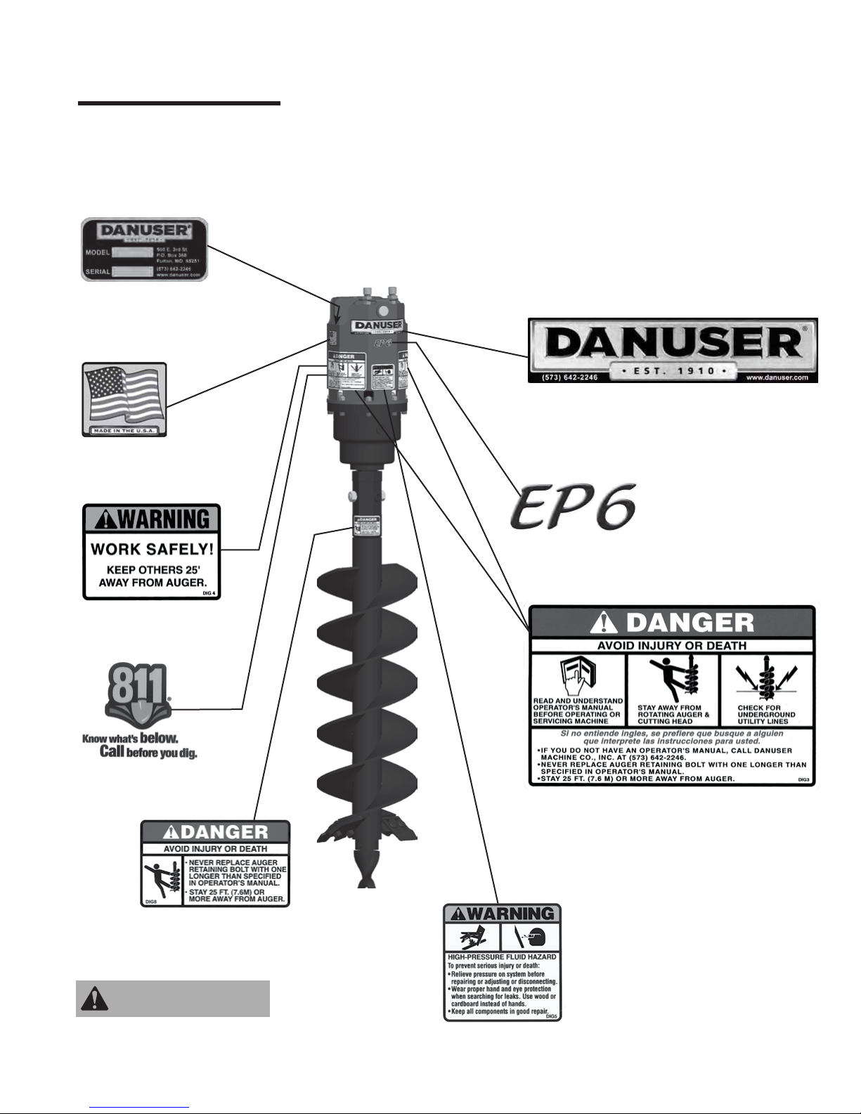
Decals &
Safety Signs
Model No. & Serial No.
Location: Drive unit,
inside right side
The earth auger comes equipped with all safety signs in place. Their locations are shown in
this section. Read and follow their instructions and ensure their care:
• Keep safety signs clean and legible at all times.
• Replace safety signs that are missing, illegible, or damaged.
• Ensure replacement parts installed during repair have safety signs attached.
To install new safety signs, follow these steps:
1. Clean the area where the safety sign is to be placed.
2. Spray a little soapy water on the surface where the safety sign is to be placed.
3. Peel the backing from the safety sign, and apply it in the position shown.
4. Firmly press the safety sign, and squeeze out the air bubbles with a straight edge (e.g., a
credit card).
PART NO. DANUSER100
Location: Drive unit, front
PART NO. 9875
Location: Drive unit, right side
PART NO. DIG4
Location: Drive unit, rear
PART NO. 20673
Location: Drive unit, rear
PART NO. 10981 (EP6)
PART NO. 10982 (EP10)
PART NO. 10983 (EP15)
PART NO. 20003 (EP20)
Location: Drive unit, front
PART NO. DIG3
Locations: Drive unit, left side;
Drive unit, right side
PART NO. DIG8
Location: Auger
WARNING
Clean or replace all safety
signs if they cannot be
clearly read and understood.
PART NO. DIG5
Location: Drive unit, front
7
Decals &
Safety Signs
(continued)
PART NO. DIG6
Locations: Knuckle ear, left side;
Knuckle ear, right side
Mini-Excavator Knuckle
PART NO. DIG7
Locations: Knuckle ear, left side;
Knuckle ear, right side
TLB & Excavator Knuckle
PART NO. DANUSER101
Locations: Quick attach plate, left side;
Quick attach plate, right side
Skid-Steer Mount
Skid-Steer Offset Mount
Euro Offset Mount
PART NO. DIG2
Location: Quick attach plate, top
PART NO. DIG27
Location: Quick attach plate, top
PART NO. DIG27
Location: Quick attach plate, top
PART NO. DIG35
Location: Quick attach plate, top
PART NO. DIG35
Location: Quick attach plate, top
PART NO. DIG41
Location: Quick attach plate, top
John Deere 200/300/400/500 Series Mount
8
PART NO. DIG27
Location: Quick attach plate, top
PART NO. DIG41
Location: Quick attach plate, top
WARNING
Clean or replace all safety
signs if they cannot be
clearly read and understood.

Drive Unit
Specifications
Minimum Hydraulic Flow 6 GPM 10 GPM 15 GPM 20 GPM
Maximum Hydraulic Flow 15 GPM 20 GPM 30 GPM 35 GPM
Maximum Continuous Operating PSI 3000 PSI 3000 PSI 3000 PSI 3000 PSI
Maximum Auger Diameter 24 inches 30 inches 36 inches 36 inches
Output Spindle 2" Hex or 2" Hex or 2" Hex or 2" Hex or
EP6EP10EP15EP20
2-9/16" Round 2-9/16" Round 2-9/16" Round 2-9/16" Round
Model EP6
PSI TORQUE
2000 1014 Ft.-Lbs.
2500 1267 Ft.-Lbs.
3000 1520 Ft.-Lbs.
PSI TORQUE
2000 1874 Ft.-Lbs.
2500 2342 Ft.-Lbs.
3000 2811 Ft.-Lbs.
GPM RPM
636
848
10 60
12 73
14 85
15 91
GPM RPM
15 49
18 59
20 65
24 78
28 92
30 98
Model EP10
PSI TORQUE
2000 1270 Ft.-Lbs.
2500 1587 Ft.-Lbs.
3000 1904 Ft.-Lbs.
Model EP20Model EP15
PSI TORQUE
2000 2465 Ft.-Lbs.
2500 3081 Ft.-Lbs.
3000 3697 Ft.-Lbs.
GPM RPM
10 48
12 58
14 68
16 77
18 87
20 97
GPM RPM
20 50
24 60
28 70
30 75
32 80
35 87
Operator's Manual Direction Terminology
Front
Left
Rear
Right
Torque and output speed specifications are based on
theoretical values and are provided for comparative
purposes only.
9

Hydraulic
Requirements
Filtration Requirements:
• A filter of, at least, 25 micron filtration is required. A filter capable of 10 micron
filtration is preferred. The majority of paper type filters are 25 microns or better.
The life of the hydraulic motor is almost entirely dependent upon cleanliness of
the oil. Instructions in your vehicle operator’s manual regarding filter and oil
changes should be carefully followed. Even small amounts of dirt in the
hydraulic oil can cause premature motor failure that is not covered by warranty.
• A low pressure type filter can be installed in the return line from the control valves to
the sump. A low pressure type filter can also be installed in the sump or pump intake
line but must be sized large enough to avoid starving the pump.
• A high pressure type filter can be used between the pump and the control valves.
• If the source of the hydraulic power does not have a filter, it will be necessary to install
one at some point in the system so, at least, part of the hydraulic oil is being filtered
whenever the system is operating. After a filter is installed and before attaching the
drive unit, the entire hydraulic system should be drained, filled with new oil, and
operated for 30 minutes or until the system is warm. During this run time, operate all
valves, cylinders, and hydraulic motors on the machine.
Pressure and Flow Requirements:
• Models EP6, EP10, EP15, and EP20 Danuser Earth Augers are designed to operate
within the pressure range of 1500 to 3000 PSI.
• Operating flow rate is dependent on model: 6 to 15 GPM for Model EP6, 10 to 20
GPM for Model EP10, 15 to 30 GPM for Model EP15, and 20 to 35 GPM for Model
EP20.
Valve Requirements:
• The hydraulic system used to power the drive unit should be equipped with a four-way
valve large enough to carry full pump outlet without restricting flow and causing oil
heating.
• The four-way valve requires a relief valve which will open and relieve extreme
pressures between the drive unit and control valve, even when the control valve is in a
neutral position. This feature can be obtained by connecting two external relief valves
between the main lines running from the control valve to the drive unit in such a way
that high pressure in either line will be relieved to the other line.
Hydraulic Hose Requirements:
• High pressure hoses of, at least, 1/2 inch inside diameter connect four-way valve to the
hydraulic fittings on the top of the drive unit. If the drive unit is mounted 10 feet or
more from the hydraulic outlets on your unit, or the pump delivers 20 GPM or more,
hose size should be increased to 3/4 inch inside diameter.
• Working pressure of hydraulic hoses must be higher than the rated vehicle hydraulic
pressure.
• An abrasion sleeve is recommended on all hydraulic hoses.
• The hydraulic hoses should be equipped with a 45-degree fitting on the drive unit end.
• The hydraulic fittings on the top of the drive unit are #10 JIC male.
• Since the motor is reversible, hose connections to motor fittings are interchangeable.
• All hoses, pipes, and fittings used to connect the drive unit should be thoroughly
cleaned before use. Care should be taken to see that no thread sealer or metal chips are
forced to the inside of the joints when connections are being tightened.
Hydraulic Fluid Selection Requirements:
• Premium grade petroleum based fluids will provide the best performance.
• Fluids that contains anti-wear agents, rust inhibitors, anti-foaming agents,and oxidation
inhibitors are recommended.
• The viscosity of the fluid should never fall below 70 SUS (13 cST). The best
10
viscosity range for the drive unit is 100-200 SUS (20-43 cST).

Assembly &
Installation
Skid-Steer Mount
Drive unit and auger
1
4
exploded views and part lists
are detailed on separate pages
in this manual.
10
9
WARNING
Personal protection
equipment including
hard hat, safety glasses,
safety shoes, and gloves
are recommended during
assembly, installation,
operation, maintenance,
service, removal, or
movement of the earth
auger. Do not allow long
hair, loose fitting
clothing, or jewelry to be
around moving and/or
rotating parts.
= Safety Sign
Location
STEP 1:
STEP 2:
Bolt cradle assembly (2) to quick attach plate assembly (1) using bolts (3), and
secure with nuts (4). Nuts (4) must be torqued to 105 ft.-lbs.
After removing bucket or other attachment from vehicle, secure quick attach plate
assembly (1) to vehicle per vehicle manufacturer’s recommendations.
3
5
6
12
7
8
2
11
REF. NO. PART NO. DESCRIPTION QTY.
1 10488 Quick Attach Plate Assembly
(includes REF. NOS. 1-5 and 9-10)
2 10965 Cradle Assembly 1
3 10975 Bolt (1/2"
4 6196 Nut (1/2"
5 10198 Knuckle Assembly 1
6 ----- Drive Unit 1
7 10193 Pin (1-1/4" x 9-1/2") 1
8 20012 Lock Pin 1
9 9598 Pin (1-1/4" x 7-1/8") 1
10 1600 Klik Pin 2
11 10038 Special Retaining Bolt - 2" Hex
(3/4"
10039 Special Retaining Bolt - 2-9/16" Rd.
(7/8"
12 10041 Nut (3/4"
10042 Nut (7/8"
13 x 1-3/4", Gr. 8) 4
13) 4
10 x 4", Gr. 8, 3/4" of thread)
9 x 4-1/4", Gr. 8, 3/4" of thread)
10) - 2" Hex 1
9) - 2-9/16" Round
1
1
CAUTION
Because of the weight of
some components, and
because some
components are difficult
to balance, two people
are required for safe
assembly and installation
of this equipment.
STEP 3:
STEP 4:
WARNING
The earth auger must be securely latched to the vehicle.
Ensure both locking handles are in the locked position with
pins fully seated. An improperly latched earth auger can
fall without warning.
Attach knuckle assembly (5) to the drive unit (6) using pin (7). Secure pin (7)
with lock pin (8).
Attach knuckle assembly/drive unit to the quick attach plate assembly (1) using
pin (9). Secure pin (9) with klik pins (10).
Proceed to STEP 5 on page 18.
11

Assembly &
Installation
Offset Skid-Steer Mount
Drive unit and auger
exploded views and part lists
are detailed on separate pages
1
in this manual.
7
6
3
2
WARNING
Personal protection
equipment including
hard hat, safety glasses,
safety shoes, and gloves
are recommended during
assembly, installation,
operation, maintenance,
service, removal, or
movement of the earth
auger. Do not allow long
hair, loose fitting
clothing, or jewelry to be
around moving and/or
rotating parts.
= Safety Sign
Location
STEP 1:
5
4
9
8
REF. NO. PART NO. DESCRIPTION QTY.
1 20652 Offset Quick Attach Plate Assembly
(includes REF. NOS. 1-2 and 6-7)
2 10198 Knuckle Assembly 1
3 ----- Drive Unit 1
4 10193 Pin (1-1/4" x 9-1/2") 1
5 20012 Lock Pin 1
6 9598 Pin (1-1/4" x 7-1/8") 1
7 1600 Klik Pin 2
8 10038 Special Retaining Bolt - 2" Hex
(3/4"
10 x 4", Gr. 8, 3/4" of thread)
10039 Special Retaining Bolt - 2-9/16" Rd.
(7/8"
9 x 4-1/4", Gr. 8, 3/4" of thread)
9 10041 Nut (3/4"
10042 Nut (7/8"
After removing bucket or other attachment from vehicle, secure quick attach plate
assembly (1) to vehicle per vehicle manufacturer’s recommendations.
10) - 2" Hex 1
9) - 2-9/16" Round
1
1
WARNING
CAUTION
Because of the weight of
some components, and
because some
components are difficult
to balance, two people
are required for safe
assembly and installation
of this equipment.
12
STEP 2:
STEP 3:
The earth auger must be securely latched to the vehicle.
Ensure both locking handles are in the locked position with
pins fully seated. An improperly latched earth auger can
fall without warning.
Attach knuckle assembly (2) to the drive unit (3) using pin (4). Secure pin (4) with
lock pin (5).
Attach knuckle assembly/drive unit to the quick attach plate assembly (1) using
pin (6). Secure pin (6) with klik pins (7).
Proceed to STEP 5 on page 18.

Assembly &
WARNING
Installation
Offset Euro Mount
= Safety Sign
Location
Drive unit and auger
exploded views and part lists
are detailed on separate pages
1
in this manual.
7
6
3
2
9
5
4
8
Personal protection
equipment including
hard hat, safety glasses,
safety shoes, and gloves
are recommended during
assembly, installation,
operation, maintenance,
service, removal, or
movement of the earth
auger. Do not allow long
hair, loose fitting
clothing, or jewelry to be
around moving and/or
rotating parts.
STEP 1:
REF. NO. PART NO. DESCRIPTION QTY.
1 20653 Offset Euro Mount Assembly
(includes REF. NOS. 1-2 and 6-7)
2 10198 Knuckle Assembly 1
3 ----- Drive Unit 1
4 10193 Pin (1-1/4" x 9-1/2") 1
5 20012 Lock Pin 1
6 9598 Pin (1-1/4" x 7-1/8") 1
7 1600 Klik Pin 2
8 10038 Special Retaining Bolt - 2" Hex
(3/4"
10 x 4", Gr. 8, 3/4" of thread)
10039 Special Retaining Bolt - 2-9/16" Rd.
(7/8"
9 x 4-1/4", Gr. 8, 3/4" of thread)
9 10041 Nut (3/4"
10042 Nut (7/8"
After removing bucket or other attachment from vehicle, secure quick attach plate
assembly (1) to vehicle per vehicle manufacturer’s recommendations.
10) - 2" Hex 1
9) - 2-9/16" Round
1
1
WARNING
CAUTION
Because of the weight of
some components, and
because some
components are difficult
to balance, two people
are required for safe
assembly and installation
of this equipment.
STEP 2:
STEP 3:
The earth auger must be securely latched to the vehicle.
Ensure both locking pins are fully seated. An improperly
latched earth auger can fall without warning.
Attach knuckle assembly (2) to the drive unit (3) using pin (4). Secure pin (4) with
lock pin (5).
Attach knuckle assembly/drive unit to the quick attach plate assembly (1) using
pin (6). Secure pin (6) with klik pins (7).
Proceed to STEP 5 on page 18.
13

Assembly &
Installation
John Deere
200/300/400/500
Series Mount
1
Drive unit and auger
exploded views and part lists
are detailed on separate pages
in this manual.
7
6
WARNING
Personal protection
equipment including
hard hat, safety glasses,
safety shoes, and gloves
are recommended during
assembly, installation,
operation, maintenance,
service, removal, or
movement of the earth
auger. Do not allow long
hair, loose fitting
clothing, or jewelry to be
around moving and/or
rotating parts.
= Safety Sign
Location
STEP 1:
2
3
5
9
4
8
REF. NO. PART NO. DESCRIPTION QTY.
1 20659 John Deere 200/300/400/500 Series
Offset Mount Assembly
(includes REF. NOS. 1-2 and 6-7)
2 10198 Knuckle Assembly 1
3 ----- Drive Unit 1
4 10193 Pin (1-1/4" x 9-1/2") 1
5 20012 Lock Pin 1
6 9598 Pin (1-1/4" x 7-1/8") 1
7 1600 Klik Pin 2
8 10038 Special Retaining Bolt - 2" Hex
(3/4"
10 x 4", Gr. 8, 3/4" of thread)
10039 Special Retaining Bolt - 2-9/16" Rd.
(7/8"
9 x 4-1/4", Gr. 8, 3/4" of thread)
9 10041 Nut (3/4"
10042 Nut (7/8"
After removing bucket or other attachment from vehicle, secure quick attach plate
assembly (1) to vehicle per vehicle manufacturer’s recommendations.
10) - 2" Hex 1
9) - 2-9/16" Round
1
1
CAUTION
Because of the weight of
some components, and
because some
components are difficult
to balance, two people
are required for safe
assembly and installation
of this equipment.
14
STEP 2:
STEP 3:
WARNING
The earth auger must be securely latched to the vehicle.
Ensure both locking pins are fully seated. An improperly
latched earth auger can fall without warning.
Attach knuckle assembly (2) to the drive unit (3) using pin (4). Secure pin (4) with
lock pin (5).
Attach knuckle assembly/drive unit to the quick attach plate assembly (1) using
pin (6). Secure pin (6) with klik pins (7).
Proceed to STEP 5 on page 18.

Assembly &
Installation
Mini-Excavator Mount
Drive unit and auger
exploded views and part lists
are detailed on separate pages
in this manual.
5
7
REF. NO. PART NO. DESCRIPTION QTY.
1 ----- Drive Unit 1
2 10219 Knuckle Sub-Assembly 1
3 10193 Pin (1-1/4" x 9-1/2") 1
4 20012 Lock Pin 1
5 ----- Ear Assembly 2
6 10220 U-Bolt (1/2"
7 6196 Nut (1/2"
8 10038 Special Retaining Bolt - 2" Hex
(3/4"
10 x 4", Gr. 8, 3/4" of thread)
10039 Special Retaining Bolt - 2-9/16" Rd.
(7/8"
9 x 4-1/4", Gr. 8, 3/4" of thread)
9 10041 Nut (3/4"
10042 Nut (7/8"
13 x 3-3/4") 4
13) 8
1
10) - 2" Hex 1
9) - 2-9/16" Round
= Safety Sign
Location
2
6
4
1
3
WARNING
Personal protection
equipment including
hard hat, safety glasses,
safety shoes, and gloves
are recommended during
assembly, installation,
operation, maintenance,
service, removal, or
movement of the earth
auger. Do not allow long
hair, loose fitting
clothing, or jewelry to be
around moving and/or
rotating parts.
CAUTION
Because of the weight of
some components, and
because some
components are difficult
to balance, two people
are required for safe
assembly and installation
of this equipment.
STEP 1:
STEP 2:
STEP 3:
STEP 4:
9
8
Attach drive unit (1) to the knuckle sub-assembly (2) using pin (3). Secure pin
(3) with lock pin (4).
Remove bucket from dipperstick, and curl cylinder pin connections. The
dipperstick pin will be used to attach the knuckle assembly to the dipperstick.
The curl cylinder pin will not be required for drive unit installation.
Space the two ear assemblies (5) to the width of the dipperstick, and secure
them to the knuckle sub-assembly (2) using u-bolts (6) and nuts (7). The ear
assemblies should be spaced evenly from the center of the knuckle
sub-assembly and the safety signs should be facing out. Nuts (7) must be
torqued to 75 ft.-lbs. Nuts (7) should be checked and re-torqued after the first
hour of use.
Attach knuckle assembly/drive unit to the dipperstick using the dipperstick pin
removed from the bucket in STEP 2. Secure the bucket pin per vehicle
manufacturer’s recommendations.
Proceed to STEP 5 on page 18.
15

Assembly &
Installation
TLB & Excavator Mount
REF. NO. PART NO. DESCRIPTION QTY.
Drive unit and auger
exploded views and part lists
are detailed on separate pages
in this manual.
7
5
1 ----- Drive Unit 1
2 10247 Knuckle Sub-Assembly 1
3 10193 Pin (1-1/4" x 9-1/2") 1
4 20012 Lock Pin 1
5 ----- Ear Assembly 2
6 10242 Tube-Clamp 2
7 10243 Bolt (5/8"
8 3092 Nut (5/8"
9 10038 Special Retaining Bolt - 2" Hex
(3/4"
10039 Special Retaining Bolt - 2-9/16" Rd.
(7/8"
10 10041 Nut (3/4"
10042 Nut (7/8"
11 x 2", Gr. 5) 4
11) 4
10 x 4", Gr. 8, 3/4" of thread)
9 x 4-1/4", Gr. 8, 3/4" of thread)
10) - 2" Hex 1
9) - 2-9/16" Round
= Safety Sign
Location
WARNING
Personal protection
equipment including
hard hat, safety glasses,
safety shoes, and gloves
are recommended during
assembly, installation,
operation, maintenance,
service, removal, or
movement of the earth
auger. Do not allow long
hair, loose fitting
clothing, or jewelry to be
around moving and/or
rotating parts.
STEP 1:
STEP 2:
Attach drive unit (1) to the knuckle sub-assembly (2) using pin (3). Secure pin
(3) with lock pin (4).
Remove bucket from dipperstick, and curl cylinder pin connections. The
dipperstick pin will be used to attach the knuckle assembly to the dipperstick.
The curl cylinder pin will not be required for drive unit installation.
2
6
8
1
1
4
3
9
10
STEP 3:
CAUTION
Because of the weight of
some components, and
because some
components are difficult
to balance, two people
are required for safe
assembly and installation
of this equipment.
16
STEP 4:
Space the two ear assemblies (5) to the width of the dipperstick, and secure
them to the knuckle sub-assembly (2) using tube-clamps (6), bolts (7), and nuts
(8). The ear assemblies should be spaced evenly from the center of the
knuckle sub-assembly and the safety signs should be facing out. Nuts (8)
must be torqued to 50 ft.-lbs. Nuts (8) should be checked and re-torqued after
the first hour of use.
Attach knuckle assembly/drive unit to the dipperstick using the dipperstick pin
removed from the bucket in STEP 2. Secure the bucket pin per vehicle
manufacturer’s recommendations.
Proceed to STEP 5 on page 18.

Assembly &
Installation
Bolt-on Bucket Mount
Drive unit and auger
exploded views and part lists
are detailed on separate pages
in this manual.
6
7
5
4
10
WARNING
Personal protection
equipment including
hard hat, safety glasses,
safety shoes, and gloves
are recommended during
assembly, installation,
operation, maintenance,
service, removal, or
movement of the earth
auger. Do not allow long
hair, loose fitting
clothing, or jewelry to be
around moving and/or
rotating parts.
CAUTION
Because of the weight of
some components, and
because some
components are difficult
to balance, two people
are required for safe
assembly and installation
of this equipment.
1
2
9
8
3
STEP 1:
STEP 2:
STEP 3:
STEP 4:
= Safety Sign
Location
REF. NO. PART NO. DESCRIPTION QTY.
1 9591B Bucket Mount Assembly 1
2 10976 Knuckle Assembly 1
3 ----- Drive Unit 1
4 10193 Pin (1-1/4" x 9-1/2") 1
5 20012 Lock Pin 1
6 9595 Pin (1-1/4" x 6") 1
7 3041 Bolt (3/8"
8 2805 Self-locking Nut (3/8"
9 10038 Special Retaining Bolt - 2" Hex
(3/4"
10039 Special Retaining Bolt - 2-9/16" Rd.
(7/8"
10 10041 Nut (3/4"
10042 Nut (7/8"
Consideration must be given to the installation location of the bolt-on bucket
mount kit. The drive unit should be able to swing during normal operation without interference from the bucket. The bucket must be constructed with sufficient
strength to safely handle the loads generated during drilling. Position the drive
unit to allow space for the hydraulic hose connections and routing of hoses.
Drill four holes in the loader bucket to accommodate bucket mount assembly (1).
Bolt bucket mount assembly (1) to the left or right outside vertical surface of the
bucket. (See figure above.) Hardware to attach the mount assembly is not
included in the kit. You will need the following:
4 bolts (1/2" diameter, Grade 5 or greater)
4 lock washers (1/2")
4 nuts (1/2")
Attach knuckle assembly (2) to the drive unit (3) using pin (4). Secure pin (4)
with lock pin (5).
Attach knuckle assembly/drive unit to mount assembly (1) using pin (6). Secure
pin (6) with bolt (7) and nut (8).
16 x 3-1/2", Gr. 8) 1
16) 1
1
10 x 4", Gr. 8, 3/4" of thread)
9 x 4-1/4", Gr. 8, 3/4" of thread)
10) - 2" Hex 1
9) - 2-9/16" Round
17

Assembly &
Installation
(continued)
STEP 5:
Grease the inside of the auger collar liberally and attach the auger with the
retaining bolt and nut that came attached to the drive unit spindle. This is a
special thread length bolt - use genuine Danuser replacement parts only. For
hex spindle, use Danuser PN 10038 (3/4"
retaining bolt and nut PN 10041. NEVER use a bolt longer than 4". For round
spindle, use Danuser PN 10039 (7/8" 9 x 4-1/4", Gr. 8, 3/4" of thread)
special retaining bolt and nut PN 10042. NEVER use a bolt longer
than 4-1/4".
10 x 4", Gr. 8, 3/4" of thread) special
WARNING
Keep hands, feet, hair,
jewelry, and clothing
away from all moving
and/or rotating parts.
STEP 6:
STEP 7:
STEP 8:
Each time an auger or extension is attached to the drive unit, the inside of the
collar should be coated liberally with grease.
The hydraulic fittings on the top of the drive unit are #10 JIC male. Install 1/2"
Danuser Hose Kit if your unit delivers less than 20 GPM. Install 3/4" Danuser
Hose Kit if your unit delivers 20 GPM or more. Danuser Hose Kits include
abrasion sleeves. Since the motor is reversible, hose connections to motor fittings
are interchangeable.
The hydraulic hoses should be equipped with a 45-degree fitting on the drive unit
end.
All hoses and fittings used to connect the earth auger should be thoroughly
cleaned before use. Care should be taken to see that no thread sealer or metal
chips are forced to the inside of the joints when connections are being tightened.
If you did not purchase quick couplers with your unit, you must obtain and install
the proper hydraulic quick couplers for your particular vehicle.
Fittings must be compatible with the fittings on your vehicle. Be sure the threads
match on the hydraulic quick couplers you are using.
After you have tightened the drive unit connections, run the hoses through the
hose holder on the quick attach plate and plug them into your auxiliary hydraulic
outlets.
18
STEP 9:
STEP 10:
WARNING
Before connecting or disconnecting hydraulic lines or
fittings, be sure to relieve all pressure by cycling all
hydraulic controls after shutdown. Remember hydraulic
systems are under pressure whenever the engine is
running and may hold pressure after shutdown.
Test the vehicle to make sure you have enough hose length to perform the full
range of the loader arms’ operating heights.
Hose routing is the responsibility of the operator. Pinched and/or stretched hoses
are not covered under the warranty.
Check the hydraulic system for leaks.
WARNING
Never check pressurized system for leaks with your bare
hand. Wear proper hand and eye protection and use wood
or cardboard when searching for suspected leaks. Oil
escaping from pinhole leaks under pressure can penetrate
skin and create a serious medical emergency. If any fluid
is injected into the skin, gangrene, blood poisoning, even
death may result. Obtain medical attention immediately.

Operation
DANGER
This earth auger is
designed for one-man
operation from the
vehicle seat. It is the
responsibility of the
operator to see that no
one is within twenty-five
feet (25') of the earth
auger when it is started
or in use. Do not operate
the earth auger with
another person near or
in contact with any part
of the drive unit or auger.
Serious personal injury
or death may result if any
attempt is made to assist
drilling operation by
hand.
DANGER
Contact with underground gas lines or electrical cables may
result in serious injury or death from explosion or electrical
shock. Before operating, call 811 or the local number to
locate underground utilities. Do not dig near underground
utility lines.
WARNING
Differences in diameter and length of auger when combined
with various heights of loader arms can allow the auger to
come into contact with skid-steer or operator when earth
auger is outside of cradle.
Before operating, check clearances between skid-steer and
auger, as well as operator and auger, across the full range
of loader arms’ operating heights.
WARNING
Keep earth auger in cradle when not drilling. To reduce the
risk of personal injury, never transport with the drive unit
out of the cradle or while the auger is rotating.
WARNING
Personal protection
equipment including
hard hat, safety glasses,
safety shoes, and gloves
are recommended during
assembly, installation,
operation, maintenance,
service, removal, or
movement of the earth
auger. Do not allow long
hair, loose fitting
clothing, or jewelry to be
around moving and/or
rotating parts.
WARNING
Safe operation of
equipment requires the
operator's full attention.
Avoid distractions such
as radio headphones,
cell phones, etc. while
operating.
DANGER
STEP 1:
STEP 2:
STEP 3:
STEP 4:
STEP 5:
WARNING
Before you operate the earth auger, check over all pins,
bolts, and connections to be sure all are securely in place.
Make sure the earth auger is securely latched to the vehicle.
Contact local utility companies to make certain there are no buried gas lines,
electrical cables, etc., in the work area. Clear area of objects that could wrap
around the auger or might be thrown. Check for ditches, stumps, holes, or other
obstacles that could cause the vehicle to roll.
Layout and mark where you want to drill your holes.
Lower the auger point slowly to the ground with the auger not powered.
Skid-steer mounted earth augers should not come in contact with the cradle during
drilling maneuvers. Drill with the quick attach plate in the horizontal position.
With the auger point lowered to the ground and before engaging the auger, move
the vehicle slowly left, right, forward, or backward as needed until the auger
appears vertical to the ground.
Actuate the hydraulics to start the auger’s rotation in the clockwise direction and
increase the speed as required so dirt is conveyed from the hole.
The hydraulic actuation lever connected to the earth auger will have three
positions: clockwise rotation, stop (neutral), and counter-clockwise rotation. The
clockwise and counter-clockwise positions may be changed by switching the hose
connections.
Do not allow riders on the
equipment at any time.
There is no safe place for
any riders.
DANGER
Never position the auger point by hand or with any tool
when the vehicle is running. Never position the auger point
by putting your hands on the auger or the drive unit.
19

Operation
(continued)
STEP 6:
The hydraulic flow rate or pressure should not exceed the earth auger’s specified
maximums. The hydraulic minimums must be met to deliver satisfactory
performance. Use only enough down pressure to assure positive penetration of
the auger into the ground. Ease up on down pressure if auger rotation slows
down drastically or stalls. Excessive down pressure will cause the auger to
frequently stall. See Hydraulic Requirements section for filtration, pressure, and
flow rate specifications.
If you have difficulty penetrating hard ground, refer to the Troubleshooting
section.
DANGER
To prevent injury, keep
an area of at least
twenty-five feet (25’)
around the auger clear of
bystanders and all other
people.
DANGER
Do not shovel dirt away
from a rotating auger, as
the shovel can be caught
and thrown by the auger.
STEP 7:
STEP 8:
STEP 9:
STEP 10:
STEP 11:
When the auger has been lowered about 24 inches into the ground, raise the auger
almost out of the hole to clear the dirt, then drill deeper and raise the auger again.
Repeat this procedure until the desired hole depth is reached.
The earth auger should be raised and lowered by changing the elevation and not
the tilt of the quick attach plate.
When the auger has reached the full depth required, allow the auger to dwell
momentarily at this depth at a slower speed to assist in cleaning out the hole.
Deactivate the earth auger, and raise it from the hole.
For “heavy” soil conditions, allow the auger to turn at slow speed while raising it
to the top of the hole.
Move away from the hole, then remove loose dirt from the auger by momentarily
actuating the earth auger and spinning it at a faster speed than used for drilling.
If necessary, repeat STEPS 8 and 9 to obtain a cleaner hole.
In some soil conditions, or when excessive down pressure is applied, the auger
may screw itself into the ground and become stuck, causing the earth auger to
stall. Do not attempt to pull the auger out of the ground. Instead, reverse the
auger rotation (counter-clockwise), and slowly raise the auger. Once unstuck,
continue operation.
If the auger becomes lodged under rocks, roots, or other large obstructions, do not
attempt to pull the auger out of the ground. If this happens, reverse the auger
rotation (counter-clockwise), and slowly raise the auger. Once unstuck, continue
operation.
WARNING
Replace a broken,
damaged, or missing
auger retaining bolt
ONLY with an authorized
factory replacement. An
auger retaining bolt that
is too long increases the
possibility of personal
injury. The auger
retaining bolt must be of
the proper size and grade
to function properly.
STEP 12:
20
Since the earth auger uses a Grade 8 retaining bolt, all vehicles must be protected
with relief valves or some other means of protection against excessive pressures.
Failure of the retaining bolt is a possible indication of excessive pressure.
Replacement of the retaining bolt should be as follows:
a) Shut off the vehicle engine, and remove the vehicle key.
b) Install a new Danuser retaining bolt. This is a special thread length bolt -
use genuine Danuser replacement parts only. For hex spindle, use Danuser
PN 10038 (3/4"
PN 10041. NEVER use a bolt longer than 4". For round spindle, use
Danuser PN 10039 (7/8"
bolt and nut PN 10042. NEVER use a bolt longer than 4-1/4".
c) Tighten the retaining bolt and nut securely.
Deactivate the auger and place the drive unit in the cradle when moving between
holes.
Frequently check the condition of the auger teeth and point, and replace them
when wear is detected. Always keep spare parts on hand for replacements to
avoid damage to the auger head and auger flighting.
10 x 4", Gr. 8, 3/4" of thread) special retaining bolt and nut
9 x 4-1/4", Gr. 8, 3/4" of thread) special retaining

Removal &
Storage
Before storage, the earth auger should be thoroughly cleaned, washing off all dirt and grime.
Make sure the hydraulic system is properly sealed against contaminants entering the unit.
Always store the earth auger in a dry, covered location.
DANGER
Never allow anyone under
the attachment at any
time.
WARNING
Personal protection
equipment including
hard hat, safety glasses,
safety shoes, and gloves
are recommended during
assembly, installation,
operation, maintenance,
service, removal, or
movement of the earth
auger. Do not allow long
hair, loose fitting
clothing, or jewelry to be
around moving and/or
rotating parts.
STEP 1:
STEP 2:
STEP 3:
STEP 4:
STEP 5:
/RZHUWKHHDUWKDXJHURQWRDÀDWOHYHOVXUIDFHLQDQDUHDZKHUHFKLOGUHQGRQRW
play.
Disconnect the hydraulic hoses from the vehicle's auxiliary hydraulics.
WARNING
Before disconnecting hydraulic lines or fittings, be sure
to relieve all pressure by cycling all hydraulic controls
after shutdown. Remember hydraulic systems are under
pressure whenever the engine is running and may hold
pressure after shutdown.
Connect the quick couplers together to prevent contaminants from entering the
earth auger's hydraulic system.
Follow your vehicle operator's manual for removing an attachment. Securely
block and support the attachment.
Tighten any loose nuts, bolts, and hydraulic components.
Replace any damaged or missing safety signs.
CAUTION
Because of the weight of
some components, and
because some
components are difficult
to balance, two people
are required for safe
assembly and installation
of this equipment.
21

Troubleshooting
Problem Possible Cause Solution
/RZÀRZ
Fittings or connections are too small or
incompatible
Slow speed
Auger will not drill
Lacks drilling power Low system pressure (PSI)
Oil leaks
Line restrictions Clear lines
'LUW\RLORURLO¿OWHU
Hydraulic pump worn or damaged See your dealer for repairs
Worn teeth or point Replace with new ones
Ground too hard and dry Order hardfaced or carbide teeth and point
Fittings loose or damaged 7LJKWHQRUUHSODFH¿WWLQJV
Hoses loose or damaged Tighten or replace hoses
Hydraulic motor seals worn or damaged See your dealer for repairs
&KHFNZLWKÀRZPHWHUDQGLIORZ
investigate the cause
5HSODFHZLWKSURSHU¿WWLQJV
&KDQJHRLODQGRLO¿OWHUDFFRUGLQJWRYHKLFOH
manufacturer's recommendation
Check with pressure gauge, and if low,
investigate the cause
Oil over heating
Hydraulic hose failure
Low quantity of hydraulic oil
Improper oil Replace with proper oil
'LUW\RLORURLO¿OWHU
Fittings loose or damaged 7LJKWHQRUUHSODFH¿WWLQJV
Hoses loose or damaged Tighten or replace hoses
Improper hose size
Hydraulic relief pressure setting too high
Hoses worn and damaged Replace hoses
Hose rating too low for hydraulic system
pressure
Hoses pinched Reroute hoses
For additional assistance, please call your dealer or contact Danuser direct:
Fill reservoir to proper level and/or
increase reservoir storage capacity
&KDQJHRLODQGRLO¿OWHUDFFRUGLQJWRYHKLFOH
manufacturer's recommendation
Check hose diameter and length requirements
Adjust vehicle hydraulic relief pressure
VHWWLQJWRZLWKLQGULYHXQLWVSHFL¿FDWLRQV
Replace with hoses with working pressure
rated higher than vehicle hydraulic pressure
22
Tel: (573) 642-2246
Fax: (573) 642-2240
E-mail: sales@danuser.com

Maintenance &
Lubrication
Proper servicing and maintenance are key to the long life of any attachment. Careful
inspection and routine maintenance helps avoid costly downtime and repair. Do not use the
earth auger with any damaged parts.
WARNING
DANGER
Never allow anyone under
the attachment at any
time.
WARNING
Personal protection
equipment including
hard hat, safety glasses,
safety shoes, and gloves
are recommended during
assembly, installation,
operation, maintenance,
service, removal, or
movement of the earth
auger. Do not allow long
hair, loose fitting
clothing, or jewelry to be
around moving and/or
rotating parts.
30
OIL LEVEL
Never check pressurized system for leaks with your bare
hand. Wear proper hand and eye protection and use wood
or cardboard when searching for suspected leaks. Oil
escaping from pinhole leaks under pressure can penetrate
skin and create a serious medical emergency. If any fluid is
injected into the skin, gangrene, blood poisoning, even
death may result. Obtain medical attention immediately.
WARNING
Do not modify the attachment. Modifications may weaken
the integrity of the attachment and may impair the safety,
function, life, and performance of the earth auger.
CAUTION
When making repairs or servicing the earth auger, use
only parts that meet original equipment manufacturer's
standards and requirements.
Maintenance Interval
Inspect the attachment for any damage, worn parts, or
cracked welds. Repair or replace as necessary.
Check for damaged or missing safety signs. Replace as
necessary.
Coat the inside diameter of the auger or extension collar
with grease.
Check all fasteners. Ensure they are tight and secure.
(See Torque Values Chart.) Replace as necessary.
Check all hydraulic components for leaks or wear.
Repair or replace as necessary.
Check planetary gear oil level to assure proper
lubrication is maintained. Check by removing the front
¿OOSOXJZLWKWKHGULYHXQLWDQJOHGDSSUR[LPDWHO\
degrees from vertical.
Check for clean hydraulic oil. At all times, keep dirt and
other contaminants from entering the hydraulic
system during connecting and disconnecting the
hydraulic system. Always use dust caps and plugs on all
quick disconnects when not in use.
&KDQJHSODQHWDU\JHDUUHGXFWLRQRLODIWHU¿UVWKRXUV
of operation or 6 months, then every 2000 hours or 12
PRQWKVZKLFKHYHUFRPHV¿UVW8VHKHDY\GXW\H[WUHPH
SUHVVXUHOXEULFDQW$3,*/:IRU¿OOLQJWKH
planetary gear reduction. Approximate oil capacity is
.90 quarts (.85 liters).
Before each use
Before each use
Each time an auger or extension
is attached
Daily
Daily
Daily
Daily
After 1st 500 hours, then every
2000 hours or yearly
23

Torque Values
Chart
%ROW+HDG,GHQWL¿FDWLRQ
Torque Values Chart
%ROW+HDG,GHQWL¿FDWLRQ
Bolt Size
(inches)
in
tpi
1/4”
20
1/4”
28
5/16”
18
5/16”
24
3/8”
16
3/8”
24
7/16”
14
7/16”
20
1/2”
13
1/2”
20
9/16”
12
9/16”
18
5/8”
11
5/8”
18
3/4”
10
3/4”
16
7/8”
9
7/8”
14
1”
8
1”
12
1-1/8”
1-1/8”
1-1/4”
1-1/4”
1-3/8”
1-3/8”
1-1/2”
1-1/2”
7RUTXHWROHUDQFHRIWRUTXHYDOXHV8QOHVVRWKHUZLVHVSHFL¿HGXVHWRUTXHYDOXHVOLVWHGDERYH
7
12
7
12
6
12
6
12
Grade 2
Nm ft.-lbs. Nm ft.-lbs. Nm ft.-lbs. mm x pitch Nm ft.-lbs. Nm ft.-lbs. Nm ft.-lbs.
7.4 5.6 11 8 16 12
8.5 613101814
15 11 24 17 33 25
17 13 26 19 37 27
27 20 42 31 59 44
31 22 47 35 67 49
43 32 67 49 95 70
49 36 75 55 105 78
66 49 105 76 145 105
75 55 115 85 165 120
95 70 150 110 210 155
105 79 165 120 235 170
130 97 205 150 285 210
150 110 230 170 325 240
235 170 360 265 510 375
260 190 405 295 570 420
225 165 585 430 820 605
250 185 640 475 905 670
340 250 875 645 1230 910
370 275 955 705 1350 995
480 355 1080 795 1750 1290
540 395 1210 890 1960 1440
680 500 1520 1120 2460 1820
750 555 1680 1240 2730 2010
890 655 1990 1470 3230 2380
1010 745 2270 1670 3680 2710
1180 870 2640 1950 4290 3160
1330 980 2970 2190 4820 3560
Grade 5
Grade 8
Bolt Size
(Metric)
M5 x 0.8
M6 x 1
M8 x 1.25
M8 x 1
M10 x 1.5
M10 x 0.75
M12 x 1.75
M12 x 1.5
M12 x 1
M14 x 2
M14 x 1.5
M16 x 2
M16 x 1.5
M18 x 2.5
M18 x 1.5
M20 x 2.5
M20 x 1.5
M24 x 3
M24 x 2
M30 x 3.5
M30 x 2
M36 x 3.5
M36 x 2
in
tpi = nominal thread diameter in inches threads per inch
Nm = Newton-meter
ft.-lbs. = foot pounds
mm x pitch = nominal thread diameter in millimeters by thread pitch
5.8 8.8
Class 5.8
436597
751181511
17 12 26 19 36 27
18 13 28 21 39 29
33 24 52 39 72 53
39 29 61 45 85 62
58 42 91 67 125 93
60 44 95 70 130 97
90 66 105 77 145 105
92 68 145 105 200 150
99 73 155 115 215 160
145 105 225 165 315 230
155 115 240 180 335 245
195 145 310 230 405 300
220 165 350 260 485 355
280 205 440 325 610 450
310 230 650 480 900 665
480 355 760 560 1050 780
525 390 830 610 1150 845
960 705 1510 1120 2100 1550
1060 785 1680 1240 2320 1710
1730 1270 2650 1950 3660 2700
1880 1380 2960 2190 4100 3220
10.9
Class 8.8 Class 10.9
KEY:
24

Drive Unit
Parts
= Safety Sign
Location
1
15
13
5
14
2
3
4
7
6
8
9
16
10
12
17
REF. NO. PART NO. DESCRIPTION QTY. MODELS
1 10180 (H) 20180 (R) Drive Unit 1 EP6 Hex or Rd.
10181 (H) 20181 (R) Drive Unit 1 EP10 Hex or Rd.
10182 (H) 20182 (R) Drive Unit 1 EP15 Hex or Rd.
20001 (H) 20184 (R) Drive Unit 1 EP20 Hex or Rd.
2 10197 Nut (7/16"
3 20186 Housing Assembly 1 EP6, EP10, EP15, EP20
4 20190 Hose Assembly 2 EP6, EP10, EP15, EP20
5 20034 #10 O-ring #8 JIC Elbow 2 EP6, EP10, EP15, EP20
6 10184 Hydraulic Motor 1 EP6
10185 Hydraulic Motor 1 EP10
10186 Hydraulic Motor 1 EP15
10964 Hydraulic Motor 1 EP20
7 10482 Socket Head Bolt (M12 x 1.75 x 35mm) 4 EP6, EP10, EP15, EP20
8 10979 O-ring 1 EP6, EP10, EP15, EP20
9 10183 Planetary Gear Reduction 1 EP6, EP10, EP15, EP20 Hex
20183 Planetary Gear Reduction 1 EP6, EP10, EP15, EP20 Rd.
10 10196 Socket Head Bolt (7/16"
11 10038 Special Retaining Bolt - 2" Hex
(3/4"
10039 Special Retaining Bolt - 2-9/16" Rd.
(7/8"
12 10041 Nut (3/4"
10042 Nut (7/8"
13 20191 Nut (7/8"
14 10193 Pin (1-1/4" x 9-1/2") 1 EP6, EP10, EP15, EP20
15 20012 Lock Pin 1 EP6, EP10, EP15, EP20
16 10980 Output Seal 1 EP6, EP10, EP15, EP20
17 10996 Output Spindle - 2" Hex 1 EP6, EP10, EP15, EP20 Hex
10997 Output Spindle - 2-9/16" Round EP6, EP10, EP15, EP20 Rd.
14) 8 EP6, EP10, EP15, EP20
14 x 2") 8 EP6, EP10, EP15, EP20
1 EP6, EP10, EP15, EP20 Hex
10 x 4", Gr. 8, 3/4" of thread)
EP6, EP10, EP15, EP20 Rd.
9 x 4-1/4", Gr. 8, 3/4" of thread)
10) - 2" Hex 1 EP6, EP10, EP15, EP20 Hex
9) - 2-9/16" Round EP6, EP10, EP15, EP20 Rd.
14) 2 EP6, EP10, EP15, EP20
11
25

Augers &
Accessories
= Safety Sign
Location
AUGER COLLAR
DESCRIPTION PART NO.
2Ǝ Hex 10328
2-9/16Ǝ Rd. 10329
DRIVE
UNIT
2Ǝ Hex to 2-9/16Ǝ Rd. 10921
2Ǝ Hex to 2Ǝ5G 10922
2-9/16Ǝ Rd. to 2Ǝ Hex 10923
2-9/16Ǝ Rd. to 2Ǝ5G 10924
2Ǝ Hex to 2-9/16Ǝ Rd. *20211
2-9/16Ǝ Rd. to 2-9/16Ǝ Rd. *20212
2Ǝ Hex to 2Ǝ5G *20214
2-9/16Ǝ Rd. to 2Ǝ5G *20215
AUGER ADAPTERS
AUGER
COLLAR
PART
NO.
*Allows attachment of augers with 1/2" diameter bolt.
VARIABLE LENGTH EXTENSIONS
LENGTH
12Ǝ ---- 10903
24Ǝ 10900 10904
48Ǝ 10901 10905
72Ǝ 10902 10906
2Ǝ HEX 2-9/16Ǝ RD.
FIXED LENGTH EXTENSIONS
LENGTH
2Ǝ HEX 2-9/16Ǝ RD.
26
12Ǝ 10910 10914
24Ǝ 10911 10915
48Ǝ 10912 10916
72Ǝ 10913 10917

Augers &
Accessories
"FAB" AUGERS - 4ƍ LENGTH
DIA.
NO. OF
TEETH
2Ǝ
HEX
2-9/16Ǝ
RD.
(continued)
FISHTAIL POINT
Dirt 10331
Hardfaced 10332
Chunky Carbide 10335
Nut 10412
Bolt 10413
4Ǝ diameter auger below
Dirt 10333
Hardfaced 10334
Chunky Carbide 10336
Nut 10412
Bolt 10416
TEETH BOLT & NUT
Carriage Bolt 10410
Nut 10411
4Ǝ 0 10600 10601
6Ǝ 2 10603 10604
8Ǝ 2 10606 10607
9Ǝ 3 10609 10610
10Ǝ 3 10612 10613
12Ǝ 4 10615 10616
15Ǝ 5 10618 10619
16Ǝ 5 10621 10622
18Ǝ 6 10624 10625
20Ǝ 6 10627 10628
24Ǝ 8 10630 10631
30Ǝ 9 10633 10634
36Ǝ 11 10636 10637
Please call Danuser for 3ƍ, 5ƍ, or 6ƍ requests.
"TREE" AUGERS - 4ƍ LENGTH
DIA.
18ƎƎ 7 10639 10640
24ƎƎ 10 10642 10643
30ƎƎ 11 10645 10646
36ƎƎ 13 10648 10649
NO. OF
TEETH
2Ǝ
HEX
2-9/16Ǝ
RD.
GAGE TOOTH
Dirt 10340
Hardfaced 10341
WISDOM TOOTH
Dirt 10337
Hardfaced 10338
Carbide 10339
CHISEL TOOTH
Dirt 10342
Hardfaced 10343
Carbide 10344
= Safety Sign
Location
"CAST" AUGERS - 4ƍ LENGTH
DIA.
6Ǝ 2 10657 10658
8Ǝ 4 10660 10661
9Ǝ 4 10663 10664
10Ǝ 4 10666 10667
12Ǝ 4 10669 10670
15Ǝ 6 10672 10673
16Ǝ 6 10675 10676
18Ǝ 6 10678 10679
20Ǝ 6 10681 10682
24Ǝ 8 10684 10685
30Ǝ 10 10687 10688
36Ǝ 12 10690 10691
Please call Danuser for 3ƍ, 5ƍ, or 6ƍ requests.
NO. OF
TEETH
2Ǝ
HEX
2-9/16Ǝ
RD.
27

Augers &
Accessories
(continued)
"BULLET" ROCK
Pilot 10758
Tooth 10759
Tooth Holder 10760
"BULLET" ROCK AUGERS
4ƍ LENGTH
DIA.
4.5Ǝ 4 10700 10701
6Ǝ 6 10703 10704
7Ǝ 8 10706 10707
8Ǝ 8 10709 10710
9Ǝ 8 10712 10713
10Ǝ 10 10715 10716
12Ǝ 12 10718 10719
15Ǝ 15 10740 10741
18Ǝ 18 10727 10728
24Ǝ 22 10730 10731
30Ǝ 24 10733 10734
36Ǝ 30 10736 10737
NO. OF
TEETH
= Safety Sign
Location
2Ǝ
HEX
2-9/16Ǝ
RD.
28
WOBBLE AUGERS - 4ƍLENGTH
DIA.
4" N/A 20600 20601
6" N/A 20603 20604
9" N/A 20606 20607
The Wobble Auger pushes through dirt, sand,
clay, asphalt, compacted rock, and embedded
rock. The 9Ǝ Wobble Auger should be used on
a skid-steer with an Operating Load or Rated
Operating Capacity of 2250 lbs. or greater,
utilizing an auger drive with 2000 ft. lbs. of
torque or greater.
See patent at danuser.com/patents.
NO. OF
TEETH
HOSE KITS & COUPLERS
1/2Ǝ+RVH.LWZLWKIODWIDFHFRXSOHUV 10050
3/4Ǝ+RVH.LWZLWKIODWIDFHFRXSOHUV 10051
1/2Ǝ+RVH.LWLQFOXGHVILWWLQJV127FRXSOHUV 10043
3/4Ǝ+RVH.LWLQFOXGHVILWWLQJV127FRXSOHUV 10044
3/4Ǝ)URQW(QG/RDGHU+RVH.LWORQJZLWK
flat face couplers and Pioneer couplers.
Mounting bracket included for bolting or welding.
Male Hydraulic Coupler 10048
Female Hydraulic Coupler 10049
21350
2Ǝ
HEX
2-9/16Ǝ
RD.
FLAT FACE ISO
COUPLERS

This page is intentionally blank.

Warranty
DANUSER
Model #
LIMITED WARRANTY
Danuser LLC (“Danuser”) warrants its products, under normal use and maintenance, to be free from defects in material and
workmanship for period(s) specified below from the purchase date from an authorized Danuser Dealer. Start of the warranty period
is determined by purchase date given on your returned WARRANTY REGISTRATION FORM. Proof of purchase may be
required. This Limited Warranty is extended only to the original purchaser of Danuser products.
EP Drive Units - 3 Years Mountings - 1 Year Augers - 1 Year
Lifetime Warranty Covering EP Drive Unit Output Pull Out
Wear Items Not Covered Under Warranty - Hydraulic Hoses, Seals, Auger Teeth, and Auger Point
1. During the applicable warranty period, Danuser, at its option, will repair or replace any part determined by Danuser to be
defective. Such repair or replacement shall take place at Danuser’s factory or a location designated by Danuser. Under no
circumstances shall Danuser be obligated for the cost of any repair or replacement by anyone other than Danuser without its
express written consent.
2. Parts may not be returned without written authorization from Danuser.
3. Some purchased components, including but not limited to hydraulic motors, planetary gears, and augers, are subject to the
inspection and warranty of the respective manufacturer. Thus, delays in a warranty determination can be expected while
Danuser awaits their decision.
4. This warranty is void if any attempt is made to make field repairs to hydraulic motors or planetary gears. To qualify for
warranty inspection, the complete drive unit must be returned in its original “failed” condition.
Serial #
5. To make a claim under this warranty, first contact your authorized Danuser Dealer. The Danuser Dealer shall complete the
Warranty Claim Form and obtain written authorization from Danuser to return parts. All warranty claims must include
detailed information regarding make and model of vehicle on which the Danuser product was mounted, hours of use,
description of events that led up to the failure, and any other information helpful in reviewing the warranty claim. All
warranty returns must be prepaid. Shipments arriving at our factory on a freight collect basis will be refused by our
receiving department. The freight charge will be credited if the parts are determined by Danuser to be defective, and the
associated freight costs in returning those parts will be prepaid by Danuser. NOTE: Hydraulic motors must arrive with all
ports sealed from dirt and moisture. If a motor arrives with open ports, the warranty is void and no inspection will be made.
6. Products or parts thereof which, as determined by Danuser’s examination, show wear from normal use, have been
improperly operated, damaged by accident or negligence, field repaired, altered or modified are not considered defective in
material and workmanship and are not covered by this warranty. This warranty does not apply to parts subject to normal
wear ("Wear Items") or to damage caused by the failure to perform recommended maintenance or to replace worn parts.
This warranty shall not obligate Danuser to bear any cost of labor for field repair, replacement, testing, or adjustment nor for
damage caused by accident, abuse, misuse, or environmental elements.
7. Any parts or labor required to repair or replace parts not covered under this warranty will be charged to the customer. Parts
repaired or replaced by Danuser are then covered by this warranty only for the remainder of the original warranty as if such
parts were original parts.
8. Danuser reserves the right to change its specifications and designs at any time.
This warranty is exclusive and in lieu of all other express warranties, if any, including the implied warranties of merchantability
and fitness for a particular purpose. It shall not extend beyond the duration of the expressed warranty provided herein and the
remedy for violations of any implied warranty shall be limited to repair or replacement of the defective part pursuant to the terms
contained herein. No employee, dealer, salesman, or representative is authorized to change this warranty in any way or grant any
other warranty. Danuser shall not be liable for any consequential, incidental, or punitive damages, losses, or expenses, including
those resulting from or caused by any defects.
Danuser LLC Tel: (573) 642-2246
500 E. 3rd St. Fax: (573) 642-2240
P.O. Box 368 E-mail: sales@danuser.com
Fulton, MO 65251 Website: www.danuser.com
Form No. 3387
 Loading...