

Page 1
POOL DEHUMIDIFIERS CDP
1
2
34
Capacity of water-cooled
condenser CDP 75
Connection Ø15 mm
Max. water flow 600 l/h
Max. capacity* 4,0 kW
Pressure drop 10 kPa
*Running conditions: LP 10°C, HP 40°C,
water temperature 28°C
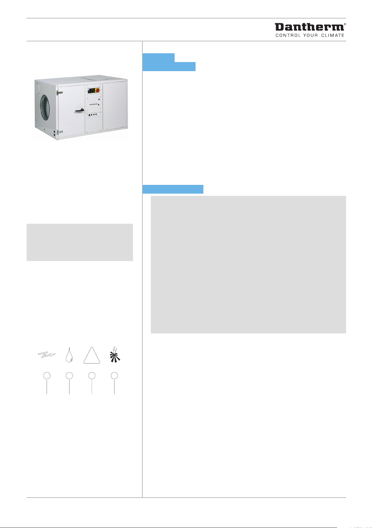
CDP 75
DEHUMIDIFIER
Function
The CDP 75 works in accordance with the condensation principle. A fan draws
the humid air into the dehumidifier and through an evaporator coil. When
passing through the evaporator the air is cooled down to below its dew point
temperature, and its content of water vapour is condensed into water, which
falls into the drip tray and then is led from the drip tray to a drain. The cold, dry
air is then passed over the condenser coil where it is re-heated, before leaving
the unit at a temperature, which is approx. 5°C higher than at the inlet.
Applications:
• Indoor swimming pools
• Therapy pools
• Wellness centres
• Hotel pools
FEATURES
• The CDP 75 is built into a cabinet made of powder-coated hot-galvanized
double-skinned panels with 50 mm insulation
• Evaporator and condenser coils are epoxy-coated for higher corrosion
resistance
• All external and internal parts of the cabinet are powder-coated
• The condensate outlet is located on the air inlet side of the CDP 75. The
outlet stub can be connected to a 3/4” water hose.
• Ø400mm air inlet through a filter placed in a removable frame
• Ø400mm dry air outlet positioned either horizontally, or vertically through
the top of the unit
• The access for inspection can be moved to the opposite side
• Fresh air inlet possible through Ø160mm fresh air duct
• The CDP 75 can be supplied with an optional water-cooled condenser. The
Ø15mm coupling pipes of the water-cooled condenser are made of copper
• The CDP 75 can be wall mounted utilising the wall mount kit or it can be placed
on the floor utilising the shockabsorbing floor mount kit (optional extra)
• A water heating coil can be mounted in the air outlet duct for further
heating of the dry air (optional extra)
Electronic control
The CDP 75 is fully automatic with electronic control. An easy to read display
panel indicates the current status of operation.
1. Power on
2. Dehumidification – the compressor is on
3. Cooling circuit failure – the dehumidifier is switched off
4. Water heating coil is activated
Push buttons allow switching on and off control of dehumidification, re-heating coil and continuous ventilation.
If a controlled and constant relative humidity is required, room or duct hygrostats can be connected to the CDP 75. If the CDP 75 is used with a waterheating coil, the control is prepared for connection of a room thermostat.
Defrosting
If the CDP 75 is used in the temperature range between 15 and 20°C, passive,
demand-controlled defrosting can be achieved by fitting a defrosting sensor
on the evaporator coil.
Page 2
POOL DEHUMIDIFIERS CDP
TECHNICAL DATA
Model CDP 75
Operating range – humidity 40 – 100 %RH
Operating range – temperature 20 – 38 °C
Air volume 1500 m3/h
Max external pressure 140 Pa
Max. fresh air supply 225 m3/h
Power supply 1x230/50 V/Hz
Max. ampere consumption 9,5 A
Max. power consumption 2,0 kW
Refrigerant R407C
Quantity of refrigerant 2,100 kg
Compressor Rotary
Sound level (at 1 metre) 58 dB(A)
Weight 130 kg
Filter EU 3
Colour RAL 9016
Protection class IPX4
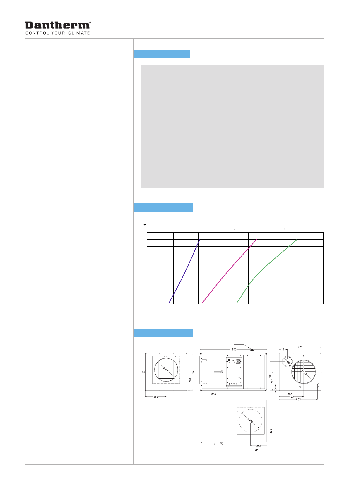
CAPACITY CURVES
40% RF
40
38
36
34
32
30
28
26
24
22
20
0,00 1,00 2,00 3,00 4,00 5,00 6,00 7,00
40% RH 60% RH 80% RH
60% RF
80% RF
DIMENSIONS
Vertical air outlet
L/H
dantherm.com
Direction of airflow
Page 3
100
POOL DEHUMIDIFIERS CDP
A
C
160
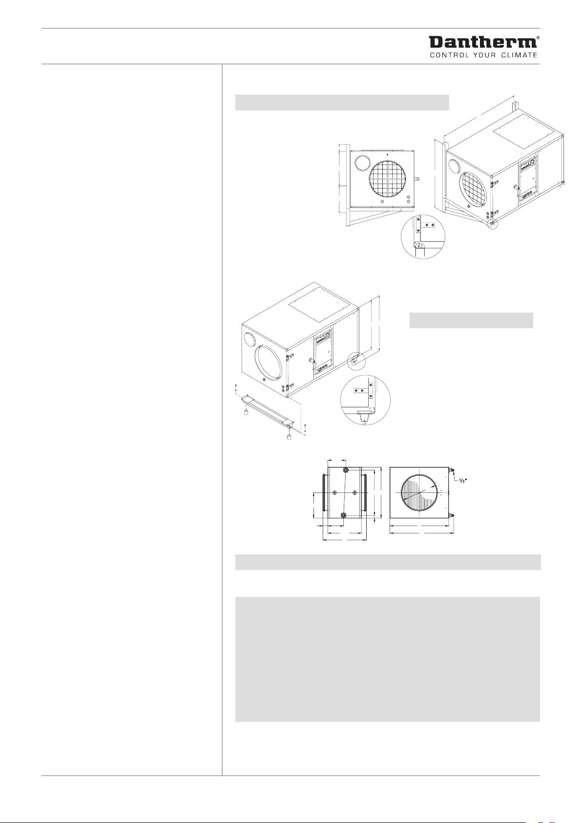
Wall mounting kit
CDP 75 A 365 B 270 C 1092 D 932
C
A
B
Shockabsorbing floor mount kit
D
The bracket is fastened by
a screw in the popnut
A
B
CDP 75 A 745±2 B 650
The floor mount kit is fastened
by a M5 sheet metal screw
Water heating coil
D25E
300
140
B
ACCESSORIES
Wall mounting kit
Shockabsorbing floor mount kit
Ø400 A 410 B 55 C 240 D 430 E 580 F 650 G 695 H 400 kg 28
Water heating coil
Room hygrostat
Capacity of water heating coils
Duct hygrostat
Room thermostat
Defrost sensor
Ext. failure monitoring kit
(see separate data sheets)
Also available in this series:
CDP 35
CDP 45
CDP 65
CDP 35T
CDP 45T
CDP 65T
CDP 125
CDP 165
(see separate data sheets)
CDP 75 2RR 2RR 2RR
Connection 1/2” 1/2” 1/2”
Duct connection mm Ø400 Ø400 Ø400
Water temperature °C 82/71 80/60 70/35
Air volume m3/h 1500 1500 1500
Air outlet temperature °C 56,78 51,67 36,56
Capacity kW 15,15 12,54 4,86
Water flow l/h 1152 504 108
Pressure drop, water kPa 5,68 1,40 0,09
Pressure drop, air Pa 11,10 11,01 10,75
The technical specifications of the water heating coils are based on a room
temperature of 27°C.
H
F
G
All dimensions are in mm.
dantherm.com
Page 4

POOL DEHUMIDIFIERS CDP
1
2
34
Capacity of water-cooled
condenser CDP 125
Connection Ø15 mm
Max. water flow 600 l/h
Max. capacity* 4,0 kW
Pressure drop 10 kPa
*Running conditions: LP 10°C, HP 40°C,
water temperature 28°C
CDP 125
DEHUMIDIFIER
Function
The CDP 125 works in accordance with the condensation principle. A fan draws
the humid air into the dehumidifier and through an evaporator coil. When
passing through the evaporator the air is cooled down to below its dew point
temperature, and its content of water vapour is condensed into water, which
falls into the drip tray and then is led from the drip tray to a drain. The cold, dry
air is then passed over the condenser coil where it is re-heated, before leaving
the unit at a temperature, which is approx. 5°C higher than at the inlet.
Applications:
• Indoor swimming pools
• Therapy pools
• Wellness centres
• Hotel pools
FEATURES
• The CDP 125 is built into a cabinet made of powder-coated hot-galvanized
double-skinned panels with 50 mm insulation
• Evaporator and condenser coils are epoxy-coated for higher corrosion
resistance
• All external and internal parts of the cabinet are powder-coated
• The condensate outlet is located on the air inlet side of the CDP 125. The
outlet stub can be connected to a 3/4” water hose
• Ø400mm air inlet through a filter placed in a removable frame
• Ø400mm dry air outlet positioned either horizontally, or vertically through the
top of the unit
• The access for inspection can be moved to the opposite side
• Fresh air inlet possible through Ø160mm fresh air duct
• The CDP 125 can be supplied with an optional water-cooled condenser. The
Ø15mm coupling pipes of the water-cooled condenser are made of copper
•
The CDP 125 can be wall mounted utilising the wall mount kit or it can be
placed on the floor utilising the shockabsorbing floor mount kit (optional extra)
• A water heating coil can be mounted in the air outlet duct for further heating
of the dry air (optional extra)
Electronic control
The CDP 125 is fully automatic with electronic control. An easy to read display
panel indicates the current status of operation.
1. Power on
2. Dehumidification – the compressor is on
3. Cooling circuit failure – the dehumidifier is switched off
4. Water heating coil is activated
Push buttons allow switching on and off control of dehumidification, re-heating coil and continuous ventilation.
If a controlled and constant relative humidity is required, room or duct hygrostats can be connected to the CDP 125. If the CDP 125 is used with a waterheating coil, the control is prepared for connection of a room thermostat.
Defrosting
If the CDP 125 is used in the temperature range between 15 and 20°C, passive,
demand-controlled defrosting can be achieved by fitting a defrosting sensor
on the evaporator coil.
Page 5

POOL DEHUMIDIFIERS CDP
TECHNICAL DATA
Model CDP 125
Operating range – humidity 40 – 100 %RH
Operating range – temperature 20 – 38 °C
Air volume 2500 m3/h
Max external pressure 230 Pa
Max. fresh air supply 375 m3/h
Power supply 1x230V;50 Hz / 3x400V;50 Hz
Max. ampere consumption 12,9 / 7,6 A
Max. power consumption 2,8 / 3,2 kW
Refrigerant R407C
Quantity of refrigerant 5,200 kg
Compressor Rotary / Reciprocating
Sound level (at 1 metre) 60 dB(A)
Weight 160 kg
Filter EU 3
Colour RAL 9016
Protection class IPX4
CAPACITY CURVES
C
40
38
36
34
32
30
28
26
24
22
20
0,00 2,00 4,00 6,00 8,00 10,00
40% RH 60% RH 80% RH
CDP 125
l/h
DIMENSIONS
dantherm.com
Vertical air outlet
Direction of airflow
Page 6

100
POOL DEHUMIDIFIERS CDP
A
C
160
Wall mounting kit
CDP 125 A 465 B 370 C 1237 D 1180
C
A
B
Shockabsorbing floor mount kit
D
The bracket is fastened by
a screw in the popnut
A
B
CDP 125 A 942±2 B 850
The floor mount kit is fastened
by a M5 sheet metal screw
Water heating coil
H
F
G
ACCESSORIES
Wall mounting kit
Shockabsorbing floor mount kit
Water heating coil
Room hygrostat
Duct hygrostat
Room thermostat
Defrost sensor
Ext. failure monitoring kit
(see separate data sheets)
D25E
300
140
B
Ø400 A 410 B 55 C 240 D 430 E 580 F 650 G 695 H 400 kg 28
Capacity of water heating coils
CDP 125 2RR 2RR 2RR
Connection 1/2” 1/2” 1/2”
Duct connection mm Ø400 Ø400 Ø400
Water temperature °C 82/71 80/60 70/35
Also available in this series:
CDP 35
CDP 45
CDP 65
CDP 75
CDP 165
CDP 35T
CDP 45T
CDP 65T
(see separate data sheets)
Air volume m3/h 2500 2500 2500
Air outlet temperature °C 51,58 47,11 34,42
Capacity kW 20,84 17,05 6,29
Water flow l/h 1620 720 144
Pressure drop, water kPa 10,09 2,44 0,15
Pressure drop, air Pa 28,63 28,42 27,84
The technical specifications of the water heating coils are based on a room
temperature of 27°C
All dimensions are in mm.
dantherm.com
Page 7

POOL DEHUMIDIFIERS CDP
1
2
34
CDP 165
DEHUMIDIFIER
Function
The CDP 165 works in accordance with the condensation principle. A fan draws
the humid air into the dehumidifier and through an evaporator coil. When
passing through the evaporator the air is cooled down to below its dew point
temperature, and its content of water vapour is condensed into water, which
falls into the drip tray and then is led from the drip tray to a drain. The cold, dry
air is then passed over the condenser coil where it is re-heated, before leaving
the unit at a temperature, which is approx. 5°C higher than at the inlet.
Applications:
• Indoor swimming pools
• Therapy pools
• Wellness centres
• Hotel pools
FEATURES
Capacity of water-cooled
condenser CDP 165
Connection Ø15 mm
Max. water flow 800 l/h
Max. capacity* 5,5 kW
Pressure drop 16 kPa
*Running conditions: LP 10°C, HP 40°C,
water temperature 28°C
• The CDP 165 is built into a cabinet made of
powder-coated
hot-galvanized
double-skinned panels with 50 mm insulation
• Evaporator and condenser coils are epoxy-coated for higher corrosion
resistance
• All external and internal parts of the cabinet are powder-coated
• The condensate outlet is located on the air inlet side of the CDP 165. The
outlet stub can be connected to a 3/4” water hose.
• Ø500mm air inlet through a filter placed in a removable frame
• Ø500mm dry air outlet positioned either horizontally, or vertically through
the top of the unit
• The access for inspection can be moved to the opposite side
• Fresh air inlet possible through Ø160mm fresh air duct
• The CDP 165 can be supplied with an optional water-cooled condenser. The
Ø15mm coupling pipes of the water-cooled condenser are made of copper
• The CDP 165 can be placed on the floor utilising the shockabsorbing floor
mount kit (optional extra)
• A water heating coil can be mounted in the air outlet duct for further
heating of the dry air (optional extra)
Electronic control
The CDP 165 is fully automatic with electronic control. An easy to read display
panel shows the current status of operation.
1. Power on
2. Dehumidification – the compressor is on
3. Cooling circuit failure – the dehumidifier is switched off
4. Water heating coil is activated
Push buttons allow switching on and off control of dehumidification, re-heating coil and continuous ventilation.
If a controlled and constant relative humidity is required, room or duct hygrostats can be connected to the CDP 165. If the CDP 165 is used with a waterheating coil, the control is prepared for connection of a room thermostat.
Defrosting
If the CDP 165 is used in the temperature range between 15 and 20°C, passive,
demand-controlled defrosting can be achieved by fitting a defrosting sensor
on the evaporator coil.
Page 8

POOL DEHUMIDIFIERS CDP
0,00 2,00 4,00 6,00 8,00 10,00 12,00
TECHNICAL DATA
Model CDP 165
Operating range – humidity 40 – 100 %RH
Operating range – temperature 20 – 38 °C
Air volume 3600 m3/h
Max external pressure 240 Pa
Max. fresh air supply 540 m3/h
Power supply 3x230/50 / 3x400/50 V/Hz
Max. ampere consumption 20,2 / 11,5 A
Max. power consumption 4,3 kW
Refrigerant R407C
Quantity of refrigerant 6,800 kg
Compressor Reciprocating
Sound level (at 1 metre) 63 dB(A)
Weight 190 kg
Filter EU 3
Colour RAL 9016
Protection class IPX4
CAPACITY CURVES
C
40
38
36
34
32
30
28
26
24
22
20
DIMENSIONS
40% RH 60% RH 80% RH
Vertical air outlet
CDP 165
l/h
dantherm.com
Direction of airflow
Page 9

POOL DEHUMIDIFIERS CDP
A
C
160
Shockabsorbing floor mount kit
A
B
CDP 165 A 1067±2 B 975
The floor mount kit is fastened
by a M5 sheet metal screw
Water heating coil
D25E
300
140
B
H
F
G
3
4
Ø500 A 410 B 55 C 352 D 655 E 705 F 775 G 820 H 500 kg 34
ACCESSORIES
Shockabsorbing floor mount kit
Water heating coil
Room hygrostat
Duct hygrostat
Room thermostat
Defrost sensor
Ext. failure monitoring kit
(see separate data sheets)
Also available in this series:
CDP 35
CDP 45
CDP 65
CDP 75
CDP 125
CDP 35T
CDP 45T
CDP 65T
(see separate data sheets)
Capacity of water heating coils
CDP 165 2RR 2RR 2RR
Connection 3/4” 3/4” 3/4”
Duct connection mm Ø500 Ø500 Ø500
Water temperature °C 82/71 80/60 70/35
Air volume m3/h 3600 3600 3600
Air outlet temperature °C 52,29 47,86 35,09
Capacity kW 30,87 25,47 9,87
Water flow l/h 2376 1080 216
Pressure drop, water kPa 13,17 3,24 0,22
Pressure drop, air Pa 25,92 25,74 25,21
The technical specifications of the water heating coils are based on a room
temperature of 27°C
All dimensions are in mm.
dantherm.com
Page 10

POOL DEHUMIDIFIERS CDP
ACCESSORIES CDP 75 - 125 - 165
Illustration Accessory CDP-type Dantherm No.
Room hygrostat CDP 75 516301
CDP 125 516301
CDP 165 516301
Room thermostat CDP 75 513321
CDP 125 513321
CDP 165 513321
Duct hygrostat CDP 75 516310
CDP 125 516310
CDP 165 516310
Wall mounting kit CDP 75 175381
CDP 125 175382
Shockabsorbing floor mount kit CDP 75 175367
CDP 125 175368
CDP 165 175369
Water heating coil CDP 75 570027
CDP 125 570027
CDP 165 570029
Defrost sensor CDP 75 175401
CDP 125 175401
CDP 165 175401
External failure monitoring kit CDP 75 019401
CDP 125 019401
CDP 165 019401
dantherm.com
 Loading...