

Maintenance and Troubleshooting Manual
00809-0100-3812, Rev AA
Rosemount™ 3812 Liquid Ultrasonic Flow
Meters
for Direct or Remote Mount Meter Electronics
April 2022
Safety and approval information
This Rosemount product complies with all applicable European directives when properly installed in accordance with the
instructions in this manual. Refer to the EU declaration of conformity for directives that apply to this product. The EU declaration
of conformity, with all applicable European directives, and the complete ATEX Installation Drawings and Instructions are available
on the internet at www.emerson.com or through your local Emerson support center.
Information affixed to equipment that complies with the Pressure Equipment Directive, can be found on the internet at http://
www.emerson.com.
For hazardous installations in Europe, refer to standard EN 60079-14 if national standards do not apply.
Other information
Full product specifications can be found in the product data sheet. Troubleshooting information can be found in the user manual.
Product data sheets and manuals are available from the Emerson website at http://www.emerson.com.
Return policy
Follow Emerson procedures when returning equipment. These procedures ensure legal compliance with government
transportation agencies and help provide a safe working environment for Emerson employees. Emerson will not accept your
returned equipment if you fail to follow Emerson procedures. Return procedures and forms are available on our web support site
at Emerson.com, or by phoning the Emerson Customer Service department.
Emerson Flow customer service
Email:
• Worldwide: http://flow.support@emerson.com
• Asia-Pacific: http://APflow.support@emerson.com
Telephone:
North and South America
United States 800 522 6277 U.K. 0870 240 1978 Australia 800 158 727
Canada +1 303 527 5200 The Netherlands +31 (0) 704 136 666 New Zealand 099 128 804
Mexico +41 (0) 41 7686 111 France 0800 917 901 India 800 440 1468
Argentina +54 11 4837 7000 Germany 0800 182 5347 Pakistan 888 550 2682
Brazil +55 15 3413 8000 Italy 8008 77334 China +86 21 2892 9000
Europe and Middle East Asia Pacific
Central & Eastern +41 (0) 41 7686 111 Japan +81 3 5769 6803
Russia/CIS +7 495 981 9811 South Korea +82 2 3438 4600
Egypt 0800 000 0015 Singapore +65 6 777 8211
Oman 800 70101 Thailand 001 800 441 6426
Qatar 431 0044 Malaysia 800 814 008
Kuwait 663 299 01
South Africa 800 991 390
Saudi Arabia 800 844 9564
UAE 800 0444 0684
2

Maintenance and Troubleshooting Manual Contents
00809-0100-3812 April 2022
Contents
Chapter 1 Routine Maintenance.................................................................................................5
1.1 Meter maintenance..................................................................................................................... 5
1.2 Field hydrostatic pressure testing procedures..............................................................................6
1.3 Routine maintenance.................................................................................................................. 7
Chapter 2 Troubleshooting...................................................................................................... 13
2.1 Meter status alarms................................................................................................................... 13
2.2 Troubleshooting the meter........................................................................................................16
2.3 Troubleshoot Maintenance log files and trend files.................................................................... 31
Chapter 3 Meter maintenance..................................................................................................37
3.1 General maintenance tasks........................................................................................................37
3.2 Important safety information.....................................................................................................38
3.3 3812 meter options................................................................................................................... 40
3.4 Remove the shrouds.................................................................................................................. 43
3.5 Re-wet the transducers..............................................................................................................52
3.6 Transducer housings or housing seals replacement................................................................... 56
3.7 Transducers replacement.......................................................................................................... 62
3.8 Meter electronics replacement.................................................................................................. 90
3.9 Transmitter electronics maintenance........................................................................................ 91
3.10 Shrouds installation............................................................................................................... 106
3.11 Meter sealing.........................................................................................................................117
Appendix A Conversion factors................................................................................................. 127
A.1 Conversion factors per units of measurement......................................................................... 127
A.2 K-Factor and inverse K-Factor.................................................................................................. 128
Appendix B Engineering drawings............................................................................................ 129
B.1 Rosemount 3812 Liquid Ultrasonic Flow Meter drawings.........................................................129
Rosemount 3812 Liquid Ultrasonic Flow Meter 3

Contents Maintenance and Troubleshooting Manual
April 2022 00809-0100-3812
4 Emerson.com/Rosemount
Maintenance and Troubleshooting Manual Routine Maintenance
00809-0100-3812 April 2022
1 Routine Maintenance
1.1 Meter maintenance
This section includes discussion of the maintenance of Rosemount 3812 Series Ultrasonic
Meters.
For reference, you may download the MeterLink Quick Start Manual from:
http://www2.emersonprocess.com/en-US/brands/Flow/ultrasonics/Pages/Ultrasonic.aspx
MeterLink may be downloaded at no charge from:
https://www.emerson.com/en-us/catalog/rosemount-sku-meterlink-diagnosticssoftware
CAUTION
SURFACE TEMPERATURE HAZARD
Meter body and piping may be extremely hot or cold.
Wear appropriate personal protective equipment when coming in contact with the meter.
Failure to comply may result in injury.
CAUTION
TRANSPORTATION HAZARD
When moving the meter, do not insert the forks of a forklift into the bore.
Inserting the forks may cause the meter to become unstable, resulting in injury to
personnel or damage to the bore and sealing face.
WARNING
CRUSHING HAZARD
During meter installation or removal, always place the unit on a stable platform or surface
that supports its assembled weight.
Failure to comply can cause the meter to roll, resulting in serious injury or equipment
damage.
CAUTION
TRIPPING HAZARD
Clear all obstacles or obstructions from the work area when transporting, installing or
removing the meter.
Failure to comply may cause injury to personnel.
Rosemount 3812 Liquid Ultrasonic Flow Meter 5

Routine Maintenance Maintenance and Troubleshooting Manual
April 2022 00809-0100-3812
CAUTION
ESCAPING FLUIDS HAZARD
The purchaser of the meter is responsible for the selection of Emerson components/seals
and materials compatible with the chemical properties of the measurement fluid.
Failure to select suitable meter components/seals may cause escaping fluids, resulting in
injury to personnel or equipment damage.
Consult your Emerson Sales and Service representative to ensure you purchase the correct
components and seals for your application, below safety message.
1.2 Field hydrostatic pressure testing procedures
The Rosemount 3812 Liquid Ultrasonic Flow Meter can be field hydrostatic tested without
any special preparations or disassembly. The transducers are not exposed to the process
pressure and can remain installed in the meter.
The liquid ultrasonic meter pressure containing parts include, but are not limited to the
transducer housings. The Hydrostatic test is verification of the pressure containing
capability of the liquid ultrasonic meter pressure containing parts and seals. Each
Rosemount Liquid Ultrasonic Flow Meter is successfully hydrostatic pressure tested prior
to shipping from the factory.
The maximum field hydrostatic pressure test must be limited to 1.5 times the stamped
maximum working pressure. The maximum working pressure is stamped on the meter ID
tag.
CAUTION
LEAKAGE OR PRESSURE CONTAINING PARTS FAILURE
Use precautions to eliminate hazards to personnel in the event of leakage or failure of the
liquid ultrasonic meter pressure containing parts or failure of the test equipment and to
prevent over-pressurization during the test procedure.
Failure to comply may result in injury to personnel or cause damage to the equipment.
NOTICE
A copy of this test is available by contacting Emerson Customer Support. Please provide
the body serial number when requesting a copy of the test report. The body serial number
is located on the downstream flange to the left of the hoist ring hole (when looking at the
flange face).
Emerson Customer Support contact information is located on the back page of the
manual.
6 Emerson.com/Rosemount

Maintenance and Troubleshooting Manual Routine Maintenance
00809-0100-3812 April 2022
1.3 Routine maintenance
Routine maintenance operations requires adherence to all applicable regulations and laws
and safety training for personnel to perform the maintenance operations. Review your
organization’s best practices procedures before performing routine maintenance.
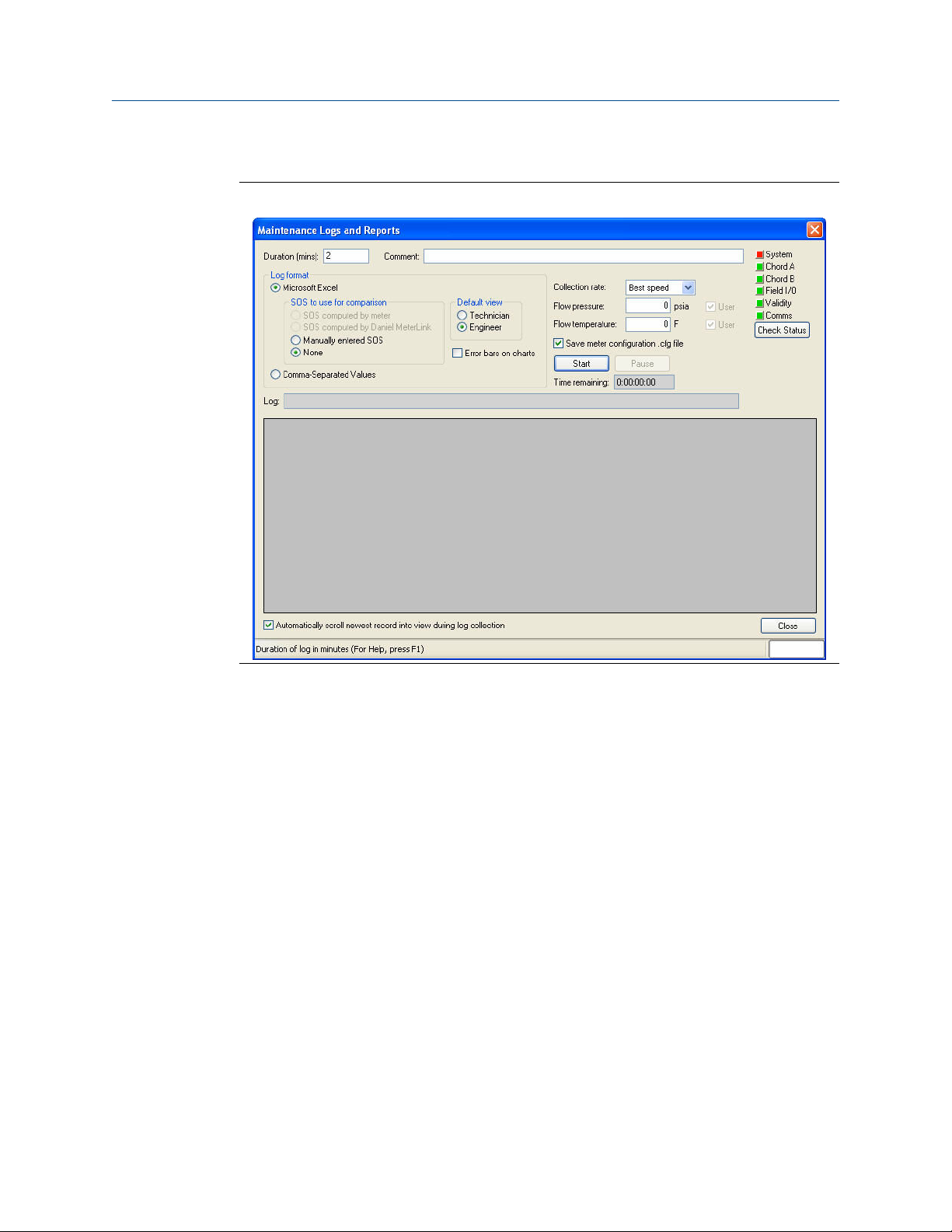
1.3.1 Maintenance logs and reports
To monitor the performance health of the meter, and ensure it is operating within
acceptable specifications, routine diagnostics should be performed. Collecting a
maintenance log gives you a snapshot of the current health of the meter and you can
compare the inspection reports from previously saved logs. Use the Logs/Reports menu
and click Maintenance Logs and Reports. MeterLink displays the Maintenance Logs and
Reports dialog. Choose the time duration, log format and collection rate for the output file
and click the Start button. You can open the file immediately after it is generated or view it
at a later time. It is recommended that a Maintenance log be collected after an upset in
the system.
In establishing a baseline to be used for the trending of the meter diagnostics, it is very
helpful if a set of log files are collected immediately after the meter has been installed in
the field. Preferably, collect the log files at several velocities within the operating range of
the meter. This helps establish that the flow profile is relatively constant throughout the
meters operating range (except velocities below 3 ft/sec where the profile may vary).
Rosemount 3812 Liquid Ultrasonic Flow Meter 7
Routine Maintenance Maintenance and Troubleshooting Manual
April 2022 00809-0100-3812
Maintenance log collection
Figure 1-1: Maintenance log collection parameters
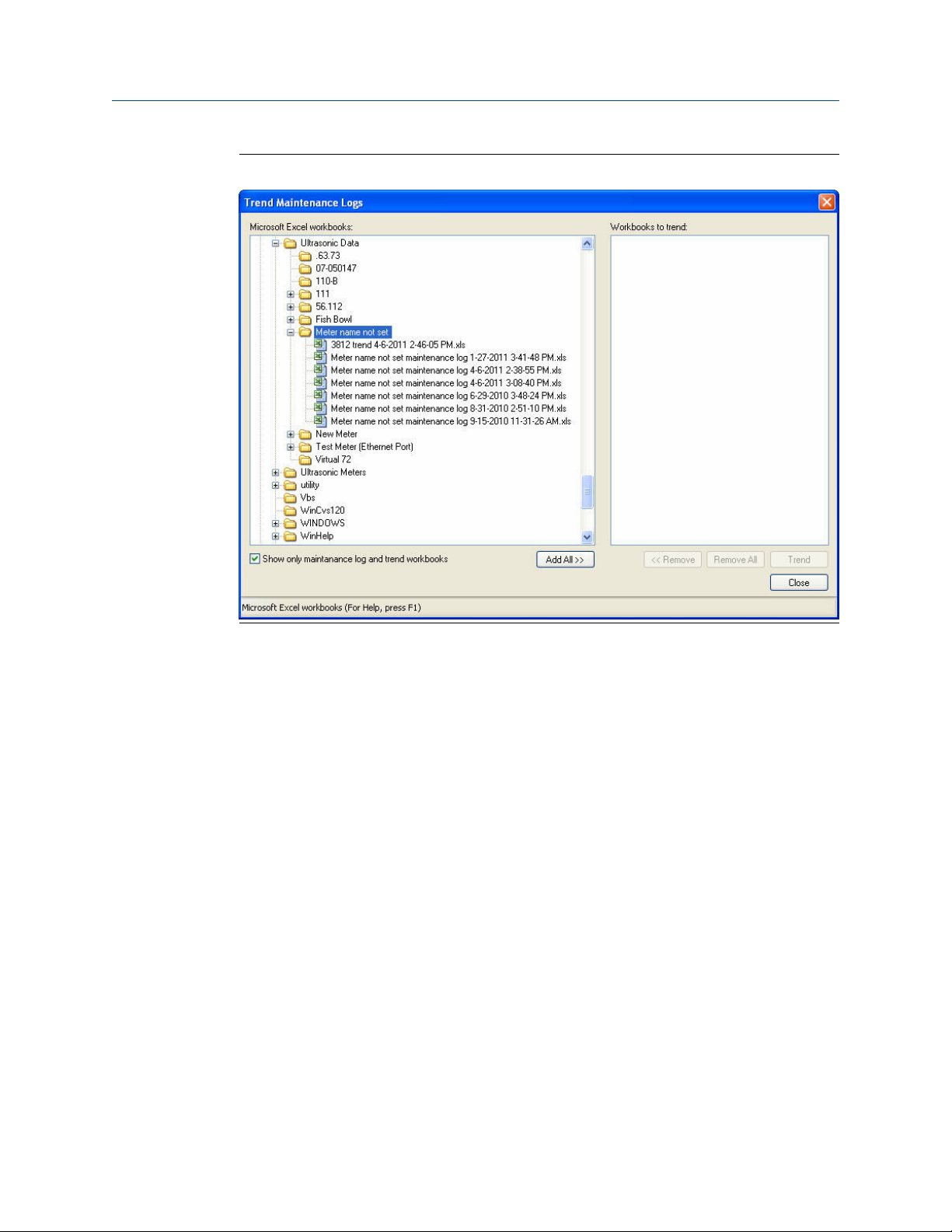
Trend maintenance log collection
Merging the results of two or more Maintenance logs into a single file, allows you to build
a historical database of the meter’s performance. Trending the logs indicates changes
from the original installation of the meter, or over time. Looking at a single inspection
report, that is either collected monthly or quarterly, can give you an indication of the
meter's health.
8 Emerson.com/Rosemount
Maintenance and Troubleshooting Manual Routine Maintenance
00809-0100-3812 April 2022
Figure 1-2: Trend log collection
This is important since many diagnostics change slowly over time. Trending the
maintenance logs helps identify these changes and makes problems much more obvious
than merely viewing a single inspection report. The Trending feature is integral to
MeterLink which allows all important parameters to be trended. MeterLink supports
trending files in a Microsoft® Excel® workbook from multiple 3812 meter maintenance
logs. Some parameters like gain, signal level, and noise level may show a shift over time
which can be useful in detecting changes in the meter and the installation.
Maintenance logs or Trend files to be trended must all have matching column headings.
This means the logs must be in the same units (i.e. U.S. Customary or Metric), must have
the same pressure type (i.e. gauge or absolute), and must have the same time base (1/
second, 1/minute, 1/hour, 1/day). If not, an error message will be displayed stating the
column headings do not match and the file will not be added to the Workbook to trend
list.
Archive log collection
Archive logs that may be collected and the options include:
• Daily log - generated every 24 hours on the Contract Hour
• Hourly log - generated every hour at the top of the hour
• Event log - collects the alarm and event log records
Rosemount 3812 Liquid Ultrasonic Flow Meter 9

Routine Maintenance Maintenance and Troubleshooting Manual
April 2022 00809-0100-3812
Figure 1-3: Archive log collection parameters
The logs may be collected in a single file or you can choose to collect one type of log. Each
of the Meter Archive logs include the Meter Configuration file.
10 Emerson.com/Rosemount
Maintenance and Troubleshooting Manual Routine Maintenance
00809-0100-3812 April 2022
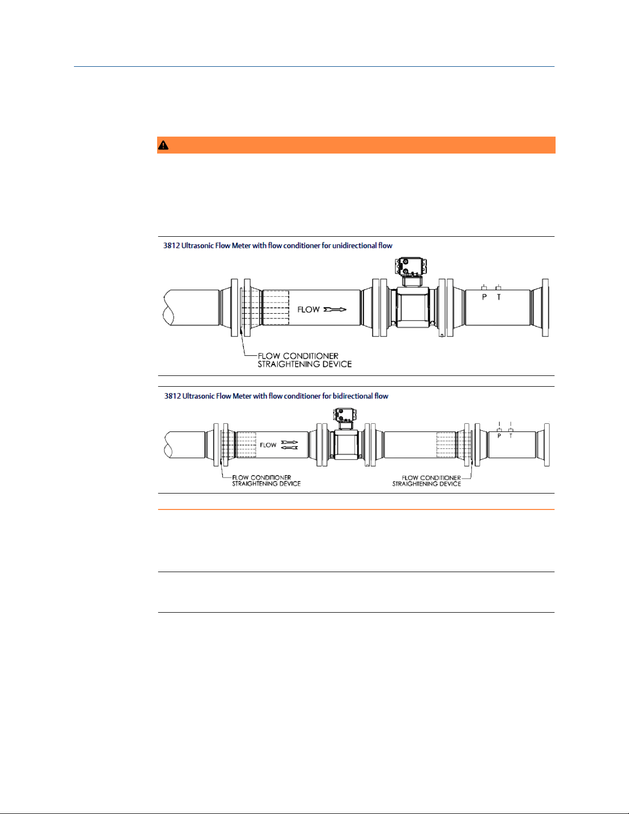
1.3.2 Pipeline cleaning maintenance
WARNING
BURST HAZARD
Before pipeline cleaning and maintenance (“pigging operations”), remove straightening
vanes or flow conditioners.
Failure to comply can cause excessive pressure in the meter system, resulting in death,
serious injury or equipment damage.
Straightening vanes or flow conditioners must be removed during pipeline cleaning
maintenance operations (“pigging operation”). If the meter run is pigged with a flow
conditioner in line, pressure may build up and cause the pipes and flanges to burst and
severely injure personnel.
Important
The excessive pressure may damage the meter or the transducer ports may collect debris
which may impede data acquisition and flow measurement.
Plugging hazard
Pipeline cleaning and maintenance (“pigging operations”) through the ultrasonic meter is
not recommended. The transducer ports may become plugged with debris and adversely
affect the transducer’s signal strength.
Rosemount 3812 Liquid Ultrasonic Flow Meter 11

Routine Maintenance Maintenance and Troubleshooting Manual
April 2022 00809-0100-3812
12 Emerson.com/Rosemount
Maintenance and Troubleshooting Manual Troubleshooting
00809-0100-3812 April 2022
2 Troubleshooting
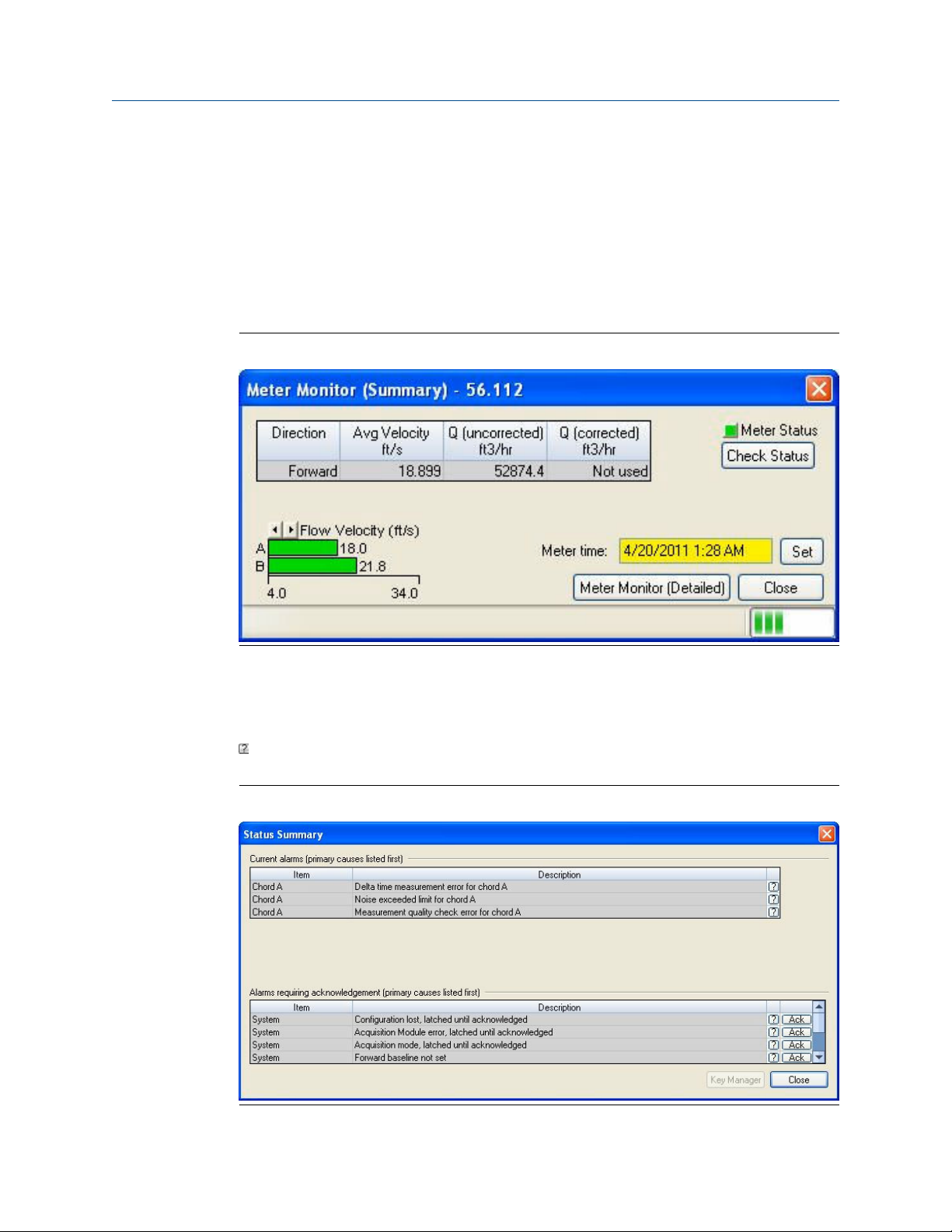
2.1 Meter status alarms
Run MeterLink and open the Meter Monitor (Summary) view to perform a diagnostics
health check.
Figure 2-1: Meter Monitor (Summary) view
If the meter is measuring flow and operating within the calibration parameters the Meter
Status LED is green. If the Meter Status LED is red, an active alarm exists that requires you
to take corrective action. Click the Check Status button to display the Status Summary
screen. The alarms are shown with the primary causes listed first. Click the question mark,
, next to the alarm to display a help topic related to the alarm and recommended actions
to resolve the issue.
Figure 2-2: Status Summary
Rosemount 3812 Liquid Ultrasonic Flow Meter 13

Troubleshooting Maintenance and Troubleshooting Manual
April 2022 00809-0100-3812
2.1.1 Check status
Click the Check Status button if any of the LEDs are yellow or red to see more specific
information causing the status alarm. Some alarms do not require an acknowledgement
and will clear automatically when the alarm condition goes away. Alarms that require a
user to acknowledge them will have a button to the right titled ACK. Clicking the ACK
button changes the button text to Wait and sends a request to the meter to clear the
alarm. The alarm will disappear from the Check Status dialog once the alarm actually
clears.
Click the Check Status button and MeterLink opens the Status Summary dialog box that
gives a short description of all alarms present.
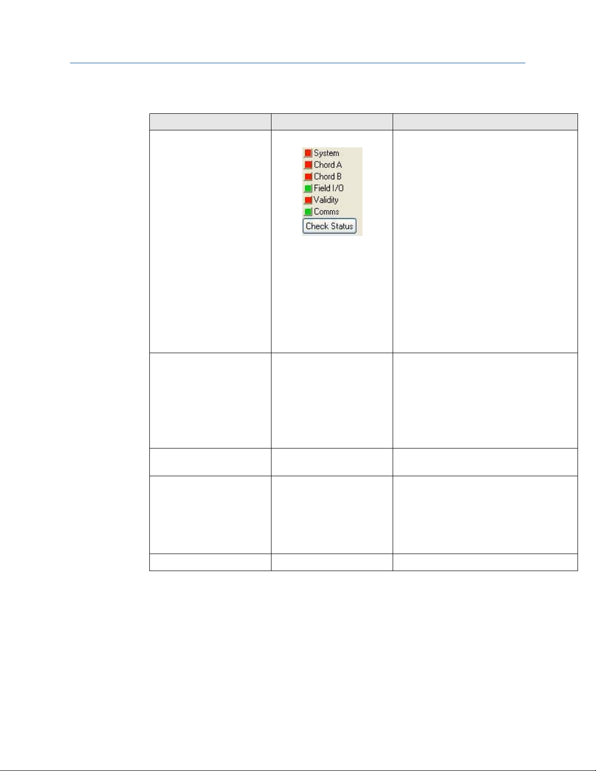
Figure 2-3: Meter Monitor Status Summary
2.1.2
A. Active alarm conditions from Meter Monitor page
B. Status Summary page with alarm examples
Following is a list and a brief description of the types of alarms:
• System
• Field I/O
• Validity
• Comms
• Check Status
System alarm
The System alarm indicates a failure in the hardware that should be addressed by a service
technician. This includes memory checksum errors and communication errors within the
hardware. A Red LED indicates a System alarm condition. Collect a Maintenance log and an
audit/alarm log and then, contact your Emerson Flow service representative.
14 Emerson.com/Rosemount
Maintenance and Troubleshooting Manual Troubleshooting
00809-0100-3812 April 2022
2.1.3 Chord A and Chord B alarm
Chord A and Chord B - These alarms indicate how a chord is functioning.
LED Color Problem
Green No alarms are present. Chord is operating properly.
Yellow At least one sample in the batch caused an alarm but it did not
cause the chord to fail. The sample will not be used in the batch.
Discarding occasional samples can occur during normal operation
such as during flow velocity changes.
Red The chord has failed or is in acquisition. This chord is not used for
this batch. Chords that have failed or are shown to be in
acquisition for repeated batches indicates that the meter should
be inspected by a service technician.
Gray The chord has manually been set to inactive, or option is not
available.
2.1.4 Field I/O alarm
Reports various field I/O devices that are in alarm. Click the Check Status button for more
details on specific alarms. The field does not appear if the meter does not support this
alarm.
2.1.5
2.1.6
2.1.7
Validity alarm
This alarm indicates that the meter may not be measuring accurately. Click Check Status
to see a description of which validity alarms are active. The validity alarms QMeter and
QFlow indicate an issue with the meter collecting enough information from the chords to
make an accurate measurement. The validity alarms for pressure and temperature
indicate that the value is above or below the alarm limits for these values. Red and green
are the only colors used for this alarm.
Comms alarm
The Comms alarm indicates that communications between MeterLink and the meter
failed. This could be due to a poor communication link. MeterLink continues to retry
communications. Red and green are the only colors used for this alarm.
Communications
The Communications Analyzer (via MeterLink Tools → Menu → Communications
Analyzer menu path) displays communications between MeterLink and the ultrasonic
meter. This utility is useful for troubleshooting communications to the meter. It displays
many of the TCP/IP commands between MeterLink and the connected meter. For
troubleshooting communications with the 475 Field Communicator for the HART
Protocol, refer to Section 5 of the Emerson 475 Field Communicator User’s Manual, Rev D.
Rosemount 3812 Liquid Ultrasonic Flow Meter 15
®

Troubleshooting Maintenance and Troubleshooting Manual
April 2022 00809-0100-3812
This manual may be downloaded from the following location: http://
www2.emersonprocess.com/en-US/brands/Field-Communicator/Pages/
Documentation.aspx
For troubleshooting communications with AMS™ Device Manager, refer to the help
documentation and support at the following web site: http://
www2.emersonprocess.com/en-US/brands/amssuite/amsdevicemanager/Pages/
AMSDeviceManager.aspx
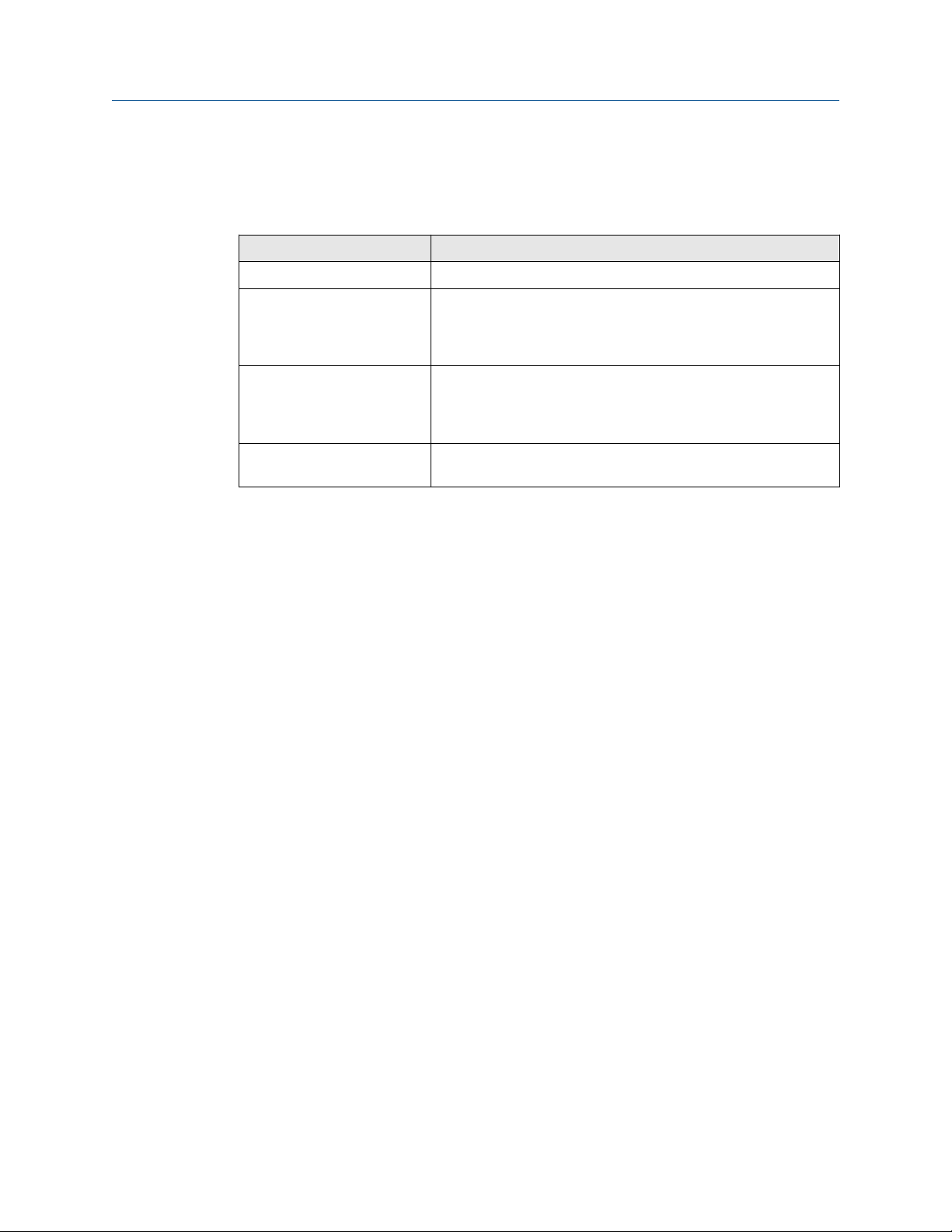
2.2 Troubleshooting the meter
Table 2-1 and the following sections show errors that may occur with the meter hardware,
firmware or connections and recommended actions to resolve the problem(s).
Table 2-1: Troubleshooting
Error Recommended action(s)
Acquisition Module Error • Check interconnect cable between Acquisition Module and
the CPU Module.
• Attempt the Program Download procedure to install the
firmware.
— Cycle power to the meter.
— Replace the Acquisition Module (see Replace the
— If the Acquisition Module cannot be reprogrammed,
(1)
Acquisition Module for direct or remote mount
electronics).
collect a complete Archive log and contact your local
area Emerson Flow service representative.
Acquisition Module is not
compatible with firmware
• Upgrade the firmware in the meter to the latest version
using MeterLink. Contact your Emerson Flow service
representative to obtain the latest firmware.
• Replace the Acquisition Module.
16 Emerson.com/Rosemount

Maintenance and Troubleshooting Manual Troubleshooting
00809-0100-3812 April 2022
Table 2-1: Troubleshooting (continued)
Error Recommended action(s)
Chord failure Chord is hard failed (Chord A or Chord B) and meter is unable to
obtain measurement data from this pair of transducers.
• If Chord A (or Chord B) is failed and no other transducers are
failed or are reporting status alerts, the issue is most likely
isolated to this pair of transducers or its cabling. Check the
transducer wiring for this pair of transducers to make sure
connections are secure and wired correctly.
• Verify that the meter run is not partially full where the top
transducer pair (Chord A) is not submerged in the process
fluid.
• Verify the average gain of this transducer pair is not above
90dB. The gain value can be read in MeterLink on the
Monitor page.
• Check the Acquisition Module transducer wiring for this pair
of transducers to make sure connections are secure and
wired correctly.
• If transducer cabling allows, swap cabling of failed
transducer pair with a pair with equal path lengths (Chord
A1 and B1, Chord A2 and B2) or access the acquisition
module and swap the cabling of the failed transducer pair
with a pair with equal path lengths. If the alarm remains
active for this chord, then the transducers are working
properly. If this alarm clears but the chord that was
swapped now fails, the issue is with the transducer.
• Collect a Maintenance Log, Configuration file and
Waveform stream file with MeterLink and contact your
Emerson Flow service representative.
CPU Module LINK LED
Rosemount 3812 Liquid Ultrasonic Flow Meter 17
• When connecting directly:
— Use a cross-over cable connection (P/N 2-3-3400-079)
• When Using a Hub:
— Use straight-through patch cable between the meter
and the hub and a straight-through patch cable
between the hub and the PC
— Do not connect either the meter or PC to the hub
UPLINK port
— Check the CPU Module LED1 is on (either solid red or
flashing green). If the LED is not on, check power to the
meter
— If the LED is on, check the Ethernet cable connections

Troubleshooting Maintenance and Troubleshooting Manual
April 2022 00809-0100-3812
Table 2-1: Troubleshooting (continued)
Error Recommended action(s)
CPU Module LINK LED is on but I
can't communicate with the
meter using Ethernet
• If you are connecting for the first time
• Enable the DHCP switch on the CPU Module
• Verify that the PC has received an IP address from the meter
as follows:
— Bring up DOS prompt window (Start → Run-(type) cmd)
— In the DOS prompt window, type ipconfig
• If you get the following: IP 192.168.135.35 (note the
last .35 can be up to .44) with a Subnet Mask of
255.255.255.0 and Default Gateway you should be able to
connect to the meter
• If you get the following:
— Ethernet adapter Local Area Connection 1:
— IP Address: 0.0.0.0
— the PC has not yet received an IP address from the DHCP
server wait (up to 30 seconds) to receive an IP address
before attempting to connect to the meter
— after 30 seconds the PC has not received an IP address
from the DHCP server or the IP address shown above
(from ipconfig) is different from the range of
192.168.135.35 through 192.168.135.44, verify that
the PC is configured to receive its IP address
automatically (via DHCP)
Communication line connected
to the flow computer but no
signal is received
Communicating with meter but
all chords display failures
Cannot communicate with
MeterLink program
• Check for loose connections at the flow meter and the flow
computer.
• Check the CPU Module settings.
• Verify that the resistance of transducers is within
specification (2 MΩ).
• Check the Acquisition Module.
• Check the interconnect cables between the Base Enclosure
and the Transmitter Electronics Enclosure.
• Ensure that the meter is properly powered.
• Ensure that the computer cable is properly connected and
check your interface pins (RS-485 or RS-232).
• Verify that the communication parameters of the MeterLink
program are correctly set.
• Check RS-485 or RS-232 communication.
18 Emerson.com/Rosemount
Maintenance and Troubleshooting Manual Troubleshooting
00809-0100-3812 April 2022
Table 2-1: Troubleshooting (continued)
Error Recommended action(s)
Cannot communicate with Field
Communicator
Cannot communicate with AMS
Device Manager
Connect to multiple meters via
Ethernet when they are on the
same LAN
Connect to multiple meters via
Ethernet when they are on the
same hub but not connected to
an intranet LAN
Refer to the Emerson 475 Field Communication User’s Manual,
Rev D. This manual may be downloaded from the following
location: http://www2.emersonprocess.com/en-US/brands/
Field-Communicator/Pages/Documentation.aspx
Note
The 375 Field Communicator is no longer available for purchase
since the release of the 475 Field Communicator. Customer
support for the 375 Field Communicator remains available.
Refer to the AMS help documentation and support at the
following web site: http://www.emersonprocess.com/ams/
suppinde.htm
• Configure each meter with a unique user-specified IP
address.
• Contact your IT department for valid IP addresses for your
LAN and Gateway addresses.
• Disable the DHCP server.
• Configure each meter with a unique user-specified IP
address.
• Assign each meter on the hub a unique IP address within
the range 192.168.135.150 through 192.168.135.254
(Gateway address for each meter may be left unconfigured
as 0.0.0.0).
• A PC may receive its IP address from an external DHCP
server; in this case, one and only one meter must have its
DHCP server enabled (the DHCP server will serve up to 10 IP
addresses to PCs attempting to talk to all meters on the
hub).
• Once a meter's IP address is configured, the meter may be
connected to the hub and accessed using that IP address.
Configuration changed
Rosemount 3812 Liquid Ultrasonic Flow Meter 19
One or more parameters have been modified in the meter's
configuration
• Collect an Audit log using MeterLink in order to see what
configuration parameters changed and when they changed.
• Run the Tools → Edit/Compare Configuration utility and
click the Write All button or select the checkbox in the
value column and click Write Checked button to write the
changes to the meter.
• Save the configuration file.

Troubleshooting Maintenance and Troubleshooting Manual
April 2022 00809-0100-3812
Table 2-1: Troubleshooting (continued)
Error Recommended action(s)
Configuration lost The meter configuration has reset to default values and the
meter is not configured correctly to measure flow and the
meter has performed a Cold Start.
• Unless the Cold Start occurred after upgrading firmware,
replace the CPU Module (see Replace the CPU Module).
• If the cold start occurred after a firmware upgrade, fully re-
configure the meter from a previously saved configuration
using the Tools → Edit/Compare Configuration in
MeterLink.
Electronics Temperature is Out
Of Nominal Range
Flow pressure is outside the
alarm limits
Temperature of the electronics is out of nominal operating
range (below -40 °C or above 100 °C) which could lead to a
system failure.
• Attempt to warm or cool the meter electronics housing.
• If the electronics is mounted to the meter and the process
fluid in the meter is over 65 °C, you must remote mount the
electronics off of the meter body.
• Collect a Maintenance log using MeterLink while the meter
is experiencing the issue and contact your Emerson Flow
service representative.
• Startup Issues:
— Verify that there is voltage to the pressure sensor from
either the meter's power supply board or from an
external power supply.
— If using an analog pressure device, verify that the
pressure sensor is properly wired to the connector.
— Verify the input is properly configured for your pressure
input.
— If using a flow computer to write pressure to the meter,
verify that it is properly writing to fixed flow pressure in
the proper units.
• Run Time Issues:
— If using an analog pressure device and input reading is 0,
check if IsAI2Avail is equal to 1 in the Meter Information
dialog in MeterLink. If it is not 1, either the I/O Board has
been removed or is damaged. Reinstall or replace the
CPU Module if this value is 0.
— If using an analog pressure device, verify that the
pressure sensor is working properly.
— If using an analog pressure device, recheck wiring and
switch settings.
— If a flow computer is writing values to the fixed flow
pressure, verify that the flow computer is still writing
valid values without Modbus write errors.
— Re-verify the pressure input settings are correct.
20 Emerson.com/Rosemount

Maintenance and Troubleshooting Manual Troubleshooting
00809-0100-3812 April 2022
Table 2-1: Troubleshooting (continued)
Error Recommended action(s)
Flow temperature is outside the
alarm limits
• Startup Issues:
— Verify that there is voltage to the temperature sensor
from either the meter's power supply board or from an
external power supply.
— If using an analog temperature device, verify that the
temperature sensor is properly wired to the connector.
— Verify the input is properly configured for your
temperature input.
— If using a flow computer to write temperature to the
meter, verify that it is properly writing to fixed flow
temperature in the proper units.
• Run Time Issues:
— If using an analog temperature device and input reading
is 0, check if IsAI2Avail is equal to 1 in the Meter
Information dialog in MeterLink. If it is not 1, either the
I/O Board has been removed or is damaged. Reinstall or
replace the CPU Module if this value is 0.
— If using an analog temperature device, verify that the
pressure sensor is working properly.
— If using an analog temperature device, recheck wiring
and switch settings.
— If a flow computer is writing values to the fixed flow
temperature, verify that the flow computer is still
writing valid values without Modbus write errors.
— Re-verify the temperature input settings are correct.
Rosemount 3812 Liquid Ultrasonic Flow Meter 21

Troubleshooting Maintenance and Troubleshooting Manual
April 2022 00809-0100-3812
Table 2-1: Troubleshooting (continued)
Error Recommended action(s)
Program download failed during
firmware upgrade
If the meter power fails during a firmware upgrade process,
perform a backup upgrade in an attempt to connect to the
meter and download the program again.
• In MeterLink go to the File pull-down menu and select
Program Settings.
• Enable the Allow FTP-only connection
• For Serial Port Connections: Connect to Port A. You may
need to adjust your Meter Directory settings for the
connection so that they match the port default settings.
Port A will default to 19200 baud with a Modbus address of
32.
• For Ethernet Connections: If you are connecting to the
meter over an Ethernet port, you should be able to connect
with the same IP address as normal. If this is unsuccessful,
the meter may have defaulted to 192.168.135.100 with a
subnet of 255.255.255.0. Make sure your PC has a
compatible address and attempt a connection using this IP
address.
• Make sure your cabling and your Meter Directory record are
setup attempt to connect to the meter.
• You will receive a message “Error 10001 opening database
connection to...”. Click OK and you will be prompted to
“Attempt FTP-only connection ….”. Click Yes and if
successful, the MeterLink caption displays “…Connected to
<meter name>…”. Go to the Tools pull down menu and
select Program Download to attempt the firmware
upgrade again.
• If the firmware upgrade is successful, the meter should start
working as normally as the meter’s configuration is not
normally lost.
• If the configuration is lost, use MeterLink Tools → Edit/
Compare Configuration to write the saved configuration
back to the meter. The saved configuration files a typically
stored in C:\Ultrasonic Data folder.
• Restart the meter to install the firmware. MeterLink
prompts you with a message that it must disconnect from
the meter. Once the firmware upgrade is complete you will
be able to reconnect to the meter with MeterLink.
• When the meter restarts, it takes about two minutes before
you will be able to reconnect depending on the firmware
upgrade being performed. If the database does need to be
reinitialized, it could take up to five minutes.
• After an upgrade, it is recommended to reconnect to the
meter and repeat the Program Download process.
22 Emerson.com/Rosemount

Maintenance and Troubleshooting Manual Troubleshooting
00809-0100-3812 April 2022
Table 2-1: Troubleshooting (continued)
Error Recommended action(s)
• If all the program components are successfully updated,
they will show to be the same date and version as the
Currently Installed Versions and the Download button will
be disabled.
• If one or more components are still not updated, click
Download to continue the upgrade process.
No power to the unit • Check that the correct voltage level is in the range of 11-36
VDC at the meter (refer to the System Wiring Diagram in
Engineering drawings).
• Check the main power source for blown fuse or tripped
circuit breaker (see Replace the fuse). Reference your “as
built” installation drawings for your location.
One or more of the chords is not
indicating a reading (reporting
zeros)
Power Failure
• Check for loose connections at the cable connectors.
• Check the resistance of the transducers (should be
approximately 2 MΩ).
• Problem also may be caused by a bad Acquisition Board or
interconnect cable.
• Check system status in the MeterLink program for any
flagged errors.
• Check the CPU Module.
• If Chord A is not indicating, change the transducer cables
from Chord B to chord A. If Chord B then fails, the
transducers are bad on Chord A.
Meter has had power removed for a period of time or the meter
restarted itself such as after a firmware upgrade. The Audit log
in the meter indicates the power fail time.
• If this was an unexpected restart of the meter, verify the
integrity of the power to the meter and make sure that the
voltage level is the in the range of 11-36 VDC at the meter.
• If this was a known power fail or restart of the meter, just
acknowledge this alarm.
Rosemount 3812 Liquid Ultrasonic Flow Meter 23

Troubleshooting Maintenance and Troubleshooting Manual
April 2022 00809-0100-3812
Table 2-1: Troubleshooting (continued)
Error Recommended action(s)
Sound velocity is outside defined
limits
Waveform contains an excessive
amount of noise
(1) Note: The latest version of the Rosemount Liquid Ultrasonic Meter firmware is available to
download from https://www.emerson.com/en-us/catalog/rosemount-sku-meterlink-
diagnostics-software
The meter's measured average sound velocity is outside the
defined limits.
• Verify that all chords are measuring the same Speed of
Sound within about 0.15%. Look for alarms that indicate
transducer problems and resolve any of these issues. This
could include failing transducers, debris buildup on
transducers, or incorrectly entered path lengths in the
configuration.
• If the chords agree, adjust the SSMin or SSMax using the
Field Setup Wizard in MeterLink so the meter's average
speed of sound falls within these limits (consult with an
Emerson Flow service representative before changing these
parameters).
• Collect a Maintenance log using MeterLink and contact your
Emerson Flow service representative.
Use the MeterLink Meter → Signal Analyzer to increase the
StackSize until noise level decreases (settings can be 1 (none)
2, 4, 8, or 16). If increasing the StackSize is not successful, try
turning on the filter or consult with Emerson Customer Support
if you are unsure of how stacking a signal can affect the meter's
operation.
2.2.1
Meter monitoring maintenance
Run MeterLink and open the Meter Monitor (Summary) to view the current health status of
your meter.
The Monitor (Summary) includes the direction of flow measurement, velocity rate, units of
measurement, uncorrected or corrected flow (if applicable for your meter) and a bar graph
for a visual comparison between the velocities for each chord.
24 Emerson.com/Rosemount

Maintenance and Troubleshooting Manual Troubleshooting
00809-0100-3812 April 2022
Figure 2-4: Meter Monitor (Summary) view
Refer to Table 2-1 for error resolutions and Table 2-2 for meter maintenance hardware
diagnostics.
Table 2-2: Maintenance
MeterLink utility Diagnostics Action(s)
Meter Monitor (Summary)
view
Check Status for active alarms • Meter Status LED is green if there are no
active alarms. This indicates the meter is
measuring flow and operating within the
calibrated parameters.
• Meter Status LED is red. This indicates an
active alarm. Resolve and acknowledge
active alarms as displayed on the Status
Summary page. Click the Help button, ,
beside the alarm description to display
information about the alarm and
recommended actions to resolve the issue.
Rosemount 3812 Liquid Ultrasonic Flow Meter 25
Troubleshooting Maintenance and Troubleshooting Manual
April 2022 00809-0100-3812
Table 2-2: Maintenance (continued)
MeterLink utility Diagnostics Action(s)
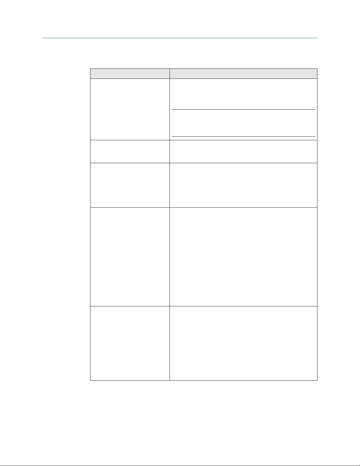
Meter Monitor (Detailed) view Flow Profile • Flow profile velocity for Chords A and B
shown on the Bar graph should be of equal
lengths and at 3 ft/s should be 1.0 (range of
0.95 to 1.05 indicates a good flow profile
velocity).
• If the velocity ratio is greater than a 10%
differential between chords, a degradation
in the symmetry is indicated.
• Check for a chord failure and resolve this
and clear the alarm.
• If installed, check the flow conditioner for
blockage.
• Compare gains and Signal to Noise (SNR)
ratios decibel values with the meter
calibration values in the Maintenance log
Inspection report.
• The meter may not be in measurement
mode or there are too few operating
chords.
• Check chord average signal amplitudes with
the meter baseline values in the
Maintenance log Inspection report.
Meter Monitor (Summary)
view Meter Flow Properties
Table
Meter Monitor (Detailed) view
Monitor Chart Selection list
Flow velocity • Check the flow direction. If reverse flow is
detected, check for valve leaks.
• If the meter run typically has reverse flow
when flow is stopped, use the Field Setup
Wizard → General Page and reconfigure
the ReverseFlowVolLmt to allow a higher
volume.
Speed of Sound • Compare Speed of Sound deviation from
measured SOS relative to the average SOS.
• Check the chord’s SOS.
• Check and correct geometry configuration
(pipe diameter, distance between the
transducers (LA), and delay time).
• If present, resolve transducer issues (failed
transducer, cabling or debris buildup on the
transducer face, or path length configured
incorrectly).
• Adjust SSMin or SSMax (consult a Emerson
Flow service representative before making
these adjustments).
26 Emerson.com/Rosemount
Maintenance and Troubleshooting Manual Troubleshooting
00809-0100-3812 April 2022
Table 2-2: Maintenance (continued)
MeterLink utility Diagnostics Action(s)
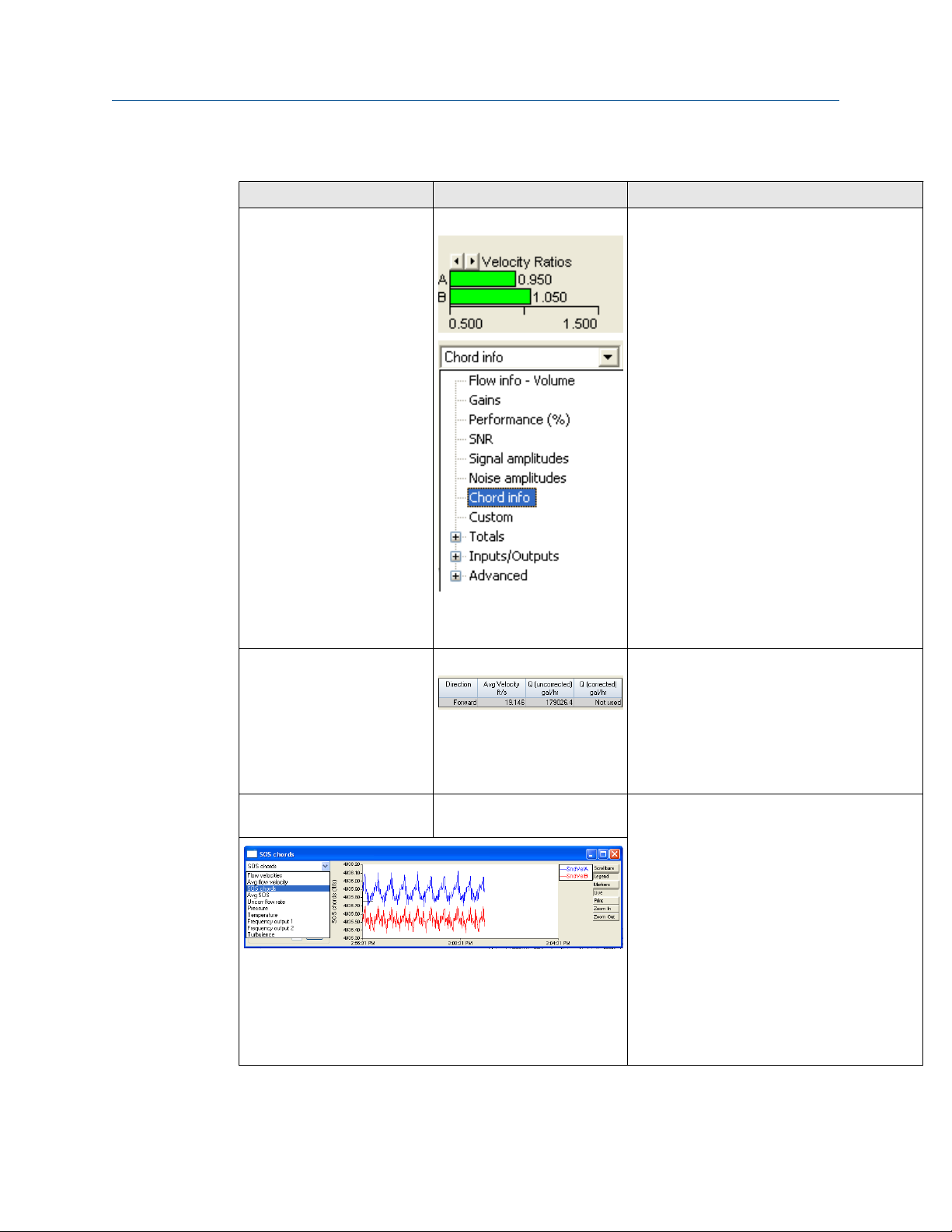
Meter Monitor (Detailed) view
Meter Data List
Meter Monitor (Detailed) view
Meter Data List
Electronics temperature out of
range
Electronics voltage out of
range
Temperature of the electronics is out of
nominal operating range below -40°C or above
100°C (-40°F or above 212°F).
• Heat or cool the meter electronics housing.
If operating temperature exceeds 65°C,
remote mount the Transmitter Electronics
Enclosure.
• CPU board system voltages are valid if 1.0V,
1.2V, 2.5V, 3.3V or the Acquisition Module
valid voltages are 1.2V, 2.5V or 3.3V.
• Replace the CPU Module if one or more of
the System Voltages is out of range.
• Replace the Acquisition Module if one or
more of the voltages is out of range.
MeterLink Tools Menu Frequency output • Run the Frequency Outputs test.
• If the output reads zero, you may require a
pull up resistor 1.2kOHM, 0.5W.
• Check frequency output from minimum to
maximum values.
Rosemount 3812 Liquid Ultrasonic Flow Meter 27

Troubleshooting Maintenance and Troubleshooting Manual
April 2022 00809-0100-3812
Table 2-2: Maintenance (continued)
MeterLink utility Diagnostics Action(s)
MeterLink Tools Menu Analog outputs Run Analog Outputs test and verify outputs are
within 4mA -20mA range
• 0% = 4mA
• 25% = 8mA
• 50% = 12mA
• 75% = 16mA
• 100% = 20 mA
MeterLink Tools Menu Digital outputs • Run Digital Outputs test.
• Digital Output Content is in relation to
frequency validity and flow direction
configuration and polarity.
Meter Electronics Acquisition Module
communications error
• If the CPU Module LED 5 is not flashing
green, check interconnect cable between
Acquisition Module and the CPU Module.
• Check firmware revision and upgrade if
necessary using MeterLink Tools →
Program Download.
• If the CPU Board LED 5 is not flashing green,
replace Acquisition Module (see Replace
the Acquisition Module for direct or remote
mount electronics).
28 Emerson.com/Rosemount
Maintenance and Troubleshooting Manual Troubleshooting
00809-0100-3812 April 2022
Table 2-2: Maintenance (continued)
MeterLink utility Diagnostics Action(s)
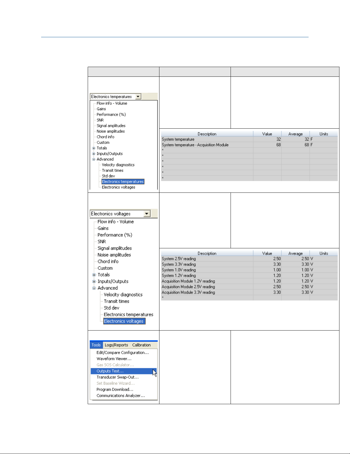
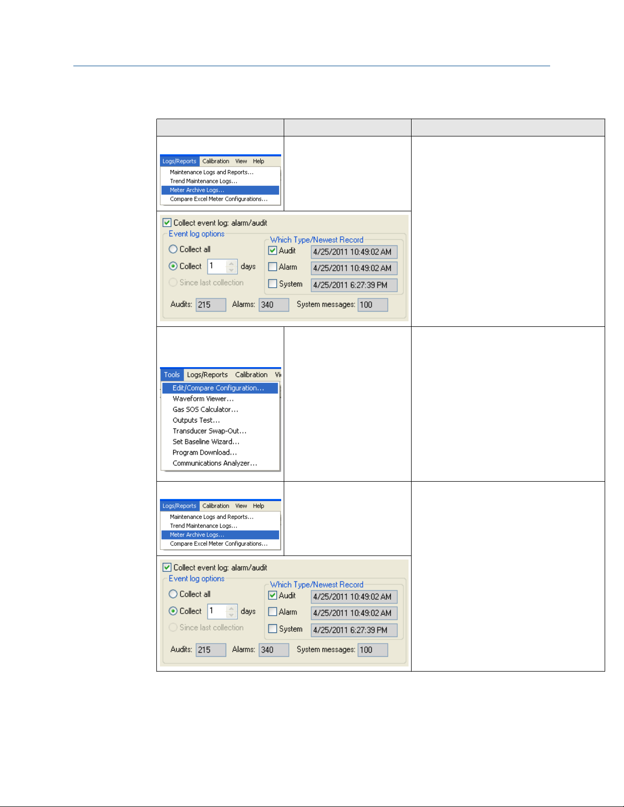
MeterLink Logs/ Reports Menu Meter performed a Warm start
or a warm start is required
MeterLink Tools → Edit/
Compare Configuration
Menu
Meter performed a Cold Start • The meter configuration has reset to
• Meter performed a Warm Start:
— Collect an Archive event log (Audit log)
using MeterLink to view configuration
parameters changes and when they
changed.
• Warm start required:
— When you make changes to the
transducer characteristics, sample rates,
the device number, or a Modbus map
file.
default values and the meter is not
configured correctly to measure flow.
• Unless the cold start occurred after
upgrading firmware, you may need to
replace the CPU Module.
• If the Cold Start occurred after a firmware
upgrade, you must reconfigure the meter
from a previously saved configuration file
using the Edit/Compare Configuration
screen. Then clear the latched alarm on the
Status Summary page.
MeterLink Logs/Reports Menu
Rosemount 3812 Liquid Ultrasonic Flow Meter 29
Power failure • If this was a known power fail or restart of
the meter just acknowledge this alarm on
the Status Summary page.
• If this was an unexpected restart of the
meter, verify the integrity of the power to
the meter and make sure that the voltage
level is in the range of 11-36 VDC at the
meter.
• Collect an Archive event log (Audit log)
using MeterLink.
Troubleshooting Maintenance and Troubleshooting Manual
April 2022 00809-0100-3812
Table 2-2: Maintenance (continued)
MeterLink utility Diagnostics Action(s)
MeterLink Meter Monitor
(Summary) view
Security seals
Chord Failure • The meter is unable to obtain measurement
data from a pair of transducers.
• The cause may be isolated to one pair of
transducers or its cabling. Check the
transducer wiring for this pair of
transducers to make sure connections are
secure and wired correctly.
• Verify that the meter run is not partially full
where this top transducer pair is not
submerged in the process fluid.
• Verify the average gain of this transducer
pair is not above 90dB. Read the value from
the MeterLink Monitor Page or using AMS
under Service Tools → Path performance.
• Remove the transducer and clean the
transducer face. Reapply coupling fluid to
the transducer face and reinstall (see
Transducers replacement).
• Endcap seals
• Endcaps latches
• Transmitter Electronics
Enclosure
• Base Enclosure
• Shroud seals
Only authorized personnel may remove
security seals. Follow your standard operating
procedure to report seals that have been
tampered with or removed and replace the
seals per instructions in Section 3.6.8 in the
Installation Manual (00825-0100-3812).
External ground wiring Transmitter Electronics
Enclosure ground lug
Conduit seals Transmitter Electronics
Enclosure
Flanges Inspect for leaks Perform leak tests on flanges
Inspect ground lug wiring and make sure the
wiring is tightly secured.
• Inspect the conduit sealant and follow your
standard operating procedure to report
tampering with the conduit sealant.
• Your operating procedures may require a
certified electrician and company witness to
reseal the conduit.
2.2.2 Unable to connect direct serial or external serial modem
If you are using Windows® XP, Windows® Vista or Windows® 7 make sure that you do not
have more than one modem driver installed to the same COM port. Typically this will only
be necessary if you use one COM port to talk direct (serial communications) and use the
same COM port to connect to an external modem. This is an apparent limitation in
Microsoft’s® Dial-up Networking. If more than one modem driver is installed for a
particular COM port, Dial-up Networking will always use the last driver installed regardless
of what is selected. The only work around is to only install one modem driver per COM port
30 Emerson.com/Rosemount
 Loading...