

Page 1

Retrofit Instructions
00825-0300-3240 , Rev AA
June 2022
Rosemount™ Gas Ultrasonic 3410 Series
Electronics Retrofit Instructions
Page 2

Retrofit Instructions June 2022
Safety and approval information
This Rosemount product complies with all applicable European directives when properly installed in
accordance with the instructions in this manual. Refer to the EU declaration of conformity for directives
that apply to this product. The EU declaration of conformity, with all applicable European directives,
and the complete ATEX Installation Drawings and Instructions are available on the internet at
www.emerson.com or through your local Emerson support center.
Information affixed to equipment that complies with the Pressure Equipment Directive, can be found
on the internet at http://www.emerson.com.
For hazardous installations in Europe, refer to standard EN 60079-14 if national standards do not apply.
Other information
Full product specifications can be found in the product data sheet. Troubleshooting information can be
found in the user manual. Product data sheets and manuals are available from the Emerson website at
http://www.emerson.com.
Return policy
Follow Emerson procedures when returning equipment. These procedures ensure legal compliance
with government transportation agencies and help provide a safe working environment for Emerson
employees. Emerson will not accept your returned equipment if you fail to follow Emerson procedures.
Return procedures and forms are available on our web support site at Emerson.com, or by phoning the
Emerson Customer Service department.
Emerson Flow customer service
Email:
• Worldwide: http://flow.support@emerson.com
• Asia-Pacific: http://APflow.support@emerson.com
Telephone:
North and South America
United States 800 522 6277 U.K. 0870 240 1978 Australia 800 158 727
Canada +1 303 527 5200 The
Mexico +41 (0) 41 7686
Argentina +54 11 4837 7000 Germany 0800 182 5347 Pakistan 888 550 2682
Brazil +55 15 3413 8000 Italy 8008 77334 China +86 21 2892 9000
111
Europe and Middle East Asia Pacific
Netherlands
France 0800 917 901 India 800 440 1468
Central &
Eastern
Russia/CIS +7 495 981 9811 South Korea +82 2 3438 4600
Egypt 0800 000 0015 Singapore +65 6 777 8211
Oman 800 70101 Thailand 001 800 441 6426
Qatar 431 0044 Malaysia 800 814 008
Kuwait 663 299 01
South Africa 800 991 390
Saudi Arabia 800 844 9564
+31 (0) 704 136
666
+41 (0) 41 7686
111
New Zealand 099 128 804
Japan +81 3 5769 6803
2 Rosemount Gas Ultrasonic 3410 Series Electronics
Page 3

June 2022 Retrofit Instructions
North and South America Europe and Middle East Asia Pacific
UAE 800 0444 0684
Contents
Plan..............................................................................................................................................5
Install......................................................................................................................................... 16
Operate......................................................................................................................................31
Mark III RS-232 and RS-485 Serial communications setup...........................................................44
Summary table of communications/output settings.................................................................. 52
3410 Communication and Output settings................................................................................ 56
3410 Series engineering drawings..............................................................................................72
Retrofit Instructions 3
Page 4

Retrofit Instructions June 2022
4 Rosemount Gas Ultrasonic 3410 Series Electronics
Page 5

June 2022 Retrofit Instructions
1 Plan
1.1 Introduction
1.1.1 General
Welcome to the Rosemount 3410 Series Ultrasonic Retrofit Instruction
Manual.
This manual has been designed to provide you with a step-by-step set of
instructions for retrofitting a meter with Mark III electronics to the new 3410
Series electronics.
NOTICE
Please read the “Before You Begin” section to make sure you have all the
components necessary to perform the before taking the meter out of
service.
Important
If retrofitting from Mark II electronics to 3410 Series electronics complete
Sections 3 and 4 in the Rosemount Ultrasonic Mark III Upgrade Kit
Instructions to determine the communications and output settings of the
Mark II electronics. Use those settings and the instructions in this manual to
configure the Series electronics.
Retrofit Instructions 5
Page 6

Retrofit Instructions June 2022
1.2 Before you begin
This section shows all of the parts and tools required to perform the
upgrade. Ensure that all of these items are available before taking the meter
out of service.
1.2.1 Tools required
Figure 1-1: Required Tools
A. ⅛-in. flat-blade screw driver
B. ¼-in. flat-blade screw driver
C. 3/8-in. drive ratchet wrench
D. 3/8-in. drive - extension - at least 3.5-in. long
E. 3/8-in. drive - 7/16-in. socket
F. Allen wrench - size 6 mm (included in Retrofit kit)
G. Crescent wrench for cable glands and electrical conduit
MeterLink™ is required to communicate with the meter electronics, access
information and collect the configuration in the meter and then convert and
download the configuration into the new 3410 Series electronics. Always
use the latest version of MeterLink™. Upgrades to the latest version are
available at: Emerson.com/Rosemount
6 Rosemount Gas Ultrasonic 3410 Series Electronics
Page 7

June 2022 Retrofit Instructions
1.3 Before removing the Electronics
1.3.1 Procedure before removing the Mark III Electronics
Procedure
1. Before removing power from the meter being retrofitted software to
connect to the meter.
2. Use the Edit/Compare Configuration screen in MeterLink
to read the configuration from the meter and save it to a file on your
computer. An example for a file name might be “Meter Name, MkIII
Final Config, 3-4-2013 10-15-02 AM.cfg”. MeterLink will be used later
in this procedure (see Configure the 3410 Series Electronics) to
convert the configuration and download it to the 3410 Series
electronics.
™
CAUTION
Loss of set-up data
The current meter configuration file must be saved before beginning
the 3410 Series electronics retrofit.
Failure to save the current configuration file can result in the loss of
important set-up data.
3 through 8 provide more detailed instructions on obtaining the
required information with respect to the communications set-up of
the electronics, however, if these settings are already known, these
steps can be skipped. Step 8 is for Frequency and Diagnostic outputs.
For reference, the known values should be entered in the Summary
table of communications/output settings in Appendix B. This
information will be required in the setup of the Series electronics. For
any setting which is not known, the applicable step(s) for obtaining
that information can be used.
3. Use the File|Meter Directory menu path, then select the
<meter name> you want to retrofit.
a) Click the Direct button on the lower left corner of the Meter
Directory dialog box.
b) The Direct Connection Properties For dialog appears.
c) Obtain the Modbus ID (same as Comms Address).
Retrofit Instructions 7
Page 8

Retrofit Instructions June 2022
Figure 1-2: Accessing Modbus ID for Ports A and B
4. Based on the information contained in the connection properties
window, enter the values for the following parameters in the
Summary table of communications/output settings in Appendix B:
Port A and B: Modbus ID = _____(enter Comms Address).
5. Exit MeterLink and disconnect your PC from the meter electronics.
The remaining information required before doing the retrofit
upgrade, is based on the wiring terminations and the settings of
various switches on the boards that comprise the electronics.
6. Power down the electronics.
CAUTION
Equipment damage
Remove power from the meter electronics.
Failure to remove power from the meter electronics may result in
damage to the equipment.
7. Remove the end caps from the upper electronics housing of the
meter to access the electronic circuit boards. See Figure 1-4 for
board layout of the 3400 stacks. See Figure 3-4 for the 3410 Series
electronics for board layout.
8 Rosemount Gas Ultrasonic 3410 Series Electronics
Page 9

June 2022 Retrofit Instructions
Figure 1-3: Remove End Caps from the Upper Electronics
Enclosure
Figure 1-4: 3400 Electronics Assembly board layout
Retrofit Instructions 9
Page 10

Retrofit Instructions June 2022
Figure 1-5: 3410 Retrofit Electronics Assembly
A. End cap and security screw
B. O-ring
C. Desiccant packet
D. CPU module
E. Optional RS-232 I/O module
F. Optional RS-485 I/O module
G. Blanking cover
H. Guide plate
I. M20 reducer
J. Ground lug - external
K. Transmitter electronics enclosure
L. Power supply
M. I.S. barrier board
N. Standoffs
O. Backplane board
P. O-ring
Q. End cap and security screw
R. O-ring
S. Acquisition cable and roll pin
T. Acquisition module assembly
U. Base enclosure
V. Cable glands
W. Gasket, base enclosure
X. Acquisition cable clamp
10 Rosemount Gas Ultrasonic 3410 Series Electronics
Page 11

June 2022 Retrofit Instructions
Y. Acquisition module
8. Remove the Mark III electronics CPU board, the HART Option Board,
and the Field Termination Board from the enclosure. Fill out the
Summary table of communications/output settings in Appendix B
based on the Field Connection Board wire terminations and/or switch
settings of the CPU board and Option Board, if installed. This
information will be used to configure the new 3410 Series electronics
later in this procedure.
Figure 1-6: Mark III CPU Board Showing Switch Settings
Retrofit Instructions 11
Page 12

Retrofit Instructions June 2022
Figure 1-7: Mark III CPU Board with I.S. Barrier Board PiggyBacked on CPU Board
1.4 Removing Mark III Electronics
1.4.1 Procedure to remove the Mark III Electronics
Procedure
1. Having obtained all the information related to the set-up of the 3400
Series electronics configuration and communications, all the
components related to the electronics can now be physically
removed from the meter. Unscrew all wiring from the Field
Termination Board. It may be helpful to label the wires to make it
easier to connect the 3410 Series electronics.
2. Remove any conduit and wiring attached to all six conduit ports.
3. Remove any ground wire attached to the ground lug on the outside
of the upper electronics housing. At this point there should be no
wires connected to the upper electronics housing.
12 Rosemount Gas Ultrasonic 3410 Series Electronics
Page 13

June 2022 Retrofit Instructions
Figure 1-8: Ground Wire Removed
4. Use the 6mm Allen wrench (supplied with retrofit kit) to remove the
two bolts holding the base enclosure.
Figure 1-9: Remove Bolts from Base Enclosure Cover
5. Remove the upper electronics housing from the base enclosure.
a) Remove the Acquisition cable, which comes down from the
upper electronics to the Acquisition module in the base
enclosure.
Retrofit Instructions 13
Page 14

Retrofit Instructions June 2022
NOTICE
Figure 1-10 shows the Acquisition module for the 3400 Series
electronics.
b) Loosen the two screws on the ends of the Acquisition cable
connector, and disconnect it from the Acquisition module.
c) Set the upper electronics housing aside once the housing is
removed.
Figure 1-10: Remove the Acquisition Cable
6. Remove all the screws that hold the transducer wires in the terminal
blocks that attach the transducers to the Acquisition module.
a) Remove the screws from the ends of the two connectors.
b) Disconnect the connectors and remove each of the
transducer wires from the connector.
7. Loosen the cable glands on the base enclosure and pull all of the
transducer cables out of the base enclosure.
8. Unscrew the three screws holding the Acquisition module in the base
enclosure and remove the Acquisition module.
The four mounting bolts holding the enclosure cover to the meter
body are sealed with an RTV silicone adhesive/sealant.
14 Rosemount Gas Ultrasonic 3410 Series Electronics
Page 15

June 2022 Retrofit Instructions
9. Remove the RTV with a flat blade screwdriver or utility knife around
the perimeter of the recessed opening and the RTV eases the
removal of the sealant.
a) Use the 7/16-in. socket wrench to remove the four mounting
bolts.
Figure 1-11: Remove Old RTV
10. Remove the base enclosure from the meter body.
11. If RTV silicone adhesive/sealant was used to seal the base enclosure
to the meter body, remove the adhesive/sealant so the 3410 base
enclosure will have a clean mounting surface.
The 3400 Series electronics should be completely removed from the
meter body at this time.
Retrofit Instructions 15
Page 16

Retrofit Instructions June 2022
2 Install
2.1 Installing the 3410 Series Electronics
2.1.1 Procedure to install the 3410 Series Electronics
Procedure
1. Remove the 3410 components from the packaging.
a) Use the 6 mm Allen wrench to remove the two screws from
the base enclosure cover.
Figure 2-1: Remove Bolts from Base Enclosure Cover
2. Lift the upper electronics housing from the base enclosure. The
acquisition cable connector from the upper electronics is attached to
the acquisition module with two screws. The cable is also secured by
a cable clamp to a mounting bolt.
a) Remove the screw securing the cable clamp and then loosen
the two screws on the acquisition cable connector and
disconnect the acquisition cable connector from the
acquisition module.
16 Rosemount Gas Ultrasonic 3410 Series Electronics
Page 17

June 2022 Retrofit Instructions
Figure 2-2: Remove Acquisition Cable and Module
3. Unscrew the remaining two mounting screws from the acquisition
module in the base enclosure and remove the acquisition board.
4. Place an insulating gasket on the meter body where the electronics
will be mounted (see gasket in Figure 1-5).
5. Place the base enclosure on top of the meter body on top of the
insulating gasket. Note that the transducer port openings on the
base enclosure are labeled with transducer locations (i.e., A1, A2, B1,
B2, C1, C2, D1, D2).
a) Orient the base so that the A1 transducer port is closest to the
A1 transducer location on the meter body. The meter body
has the transducer location labels embossed in the body next
to each transducer boss. The ports on the base enclosure
must be oriented outward (towards the sides of the meter
body, perpendicular to meter axis).
Figure 2-3: Base Enclosure Orientation
6. Use the four ¼-in. bolts with stainless steel washers and nylon
shoulder washers to secure the base enclosure to the meter body.
a) Use a nut driver to tighten the bolts to a torque of 55 to 65
inch-lbs.
Retrofit Instructions 17
Page 18

Retrofit Instructions June 2022
Figure 2-4: Insert ¼-in. Bolts
7. Fill up the base enclosure wells with RTV adhesive/sealant around
and over the four ¼-in. bolts.
This will ensure a water-tight seal. Any excess sealant can be
removed by using a scraper to leave the sealant flush with the top of
the well. Excess sealant will adhere to the acquisition board when it is
installed, and make future removal of the board difficult.
Figure 2-5: Apply RTV Sealant Around Bolts
8. Insert the Acquisition board in the base enclosure and secure it with
the two screws as shown for now.
18 Rosemount Gas Ultrasonic 3410 Series Electronics
Page 19

June 2022 Retrofit Instructions
Figure 2-6: Acquisition Module Attachment Screws
Figure 2-7: Acquisition Module Wiring
9. Route the transducer cables through the cable glands with the
correct label number (i.e. A1) which matches the label on the
transducer cable.
Figure 2-8: Base Enclosure Cable Glands Installation
10. Judge the proper length and cut off the excess.
Retrofit Instructions 19
Page 20

Retrofit Instructions June 2022
11. Strip the outer insulation, outer shield, and inner insulation using a
utility knife. Verify that insulation of individual wires was not cut
while removing outer layers. Strip each wire 0.28-in.
Figure 2-9: Transducer Cable Cut Instructions
12. Insert tubing over wires, inner insulation and under shield
approximately 1.5-in. of shield should overlap.
13. Insert and secure transducer cables through cable glands verify Line
Mark is as referenced in Figure 2-8.
Figure 2-10: Line Mark
14. Using a torque screwdriver set to 34 ±2 oz.-in., secure the wires to
the terminal plugs of the Acquisition Module.
15. Verify the cable lengths are still an appropriate length and if
necessary, cut the transducer cables to the correct length with
allowance for the wiring terminations and connector placement.
16. Ensure that the contacts clamp on the bare wires and not on the wire
insulation when the wires are being terminated on the connector.
a) Leave the connector plugged into the Acquisition board while
terminating the individual wires.
b) Tighten the connector screws on the either end of the
connector after terminating all the wires on the applicable
connector.
c) Repeat this procedure for the transducer cables on the other
side of the meter.
20 Rosemount Gas Ultrasonic 3410 Series Electronics
Page 21

June 2022 Retrofit Instructions
Figure 2-11: Install Cable and Secure Wires
17. Use the cable ties to dress the transducer cables. They should be
dressed in groups of two: A1 and C1, D1 and B1, A2 and C2, D2 and
B2. Install one cable tie at three inches from the base enclosure and
another about the point where the cables start to bend and separate
out to their respective port.
Retrofit Instructions 21
Page 22

Retrofit Instructions June 2022
Figure 2-12: Re-oriented and Secured Transducer Cables
18. Reconnect the acquisition cable connector to the acquisition module
and secure the cable connector by tightening the two screws.
19. Install the cable clamp on the Acquisition cable and secure it with the
final mounting screw for the Acquisition module.
22 Rosemount Gas Ultrasonic 3410 Series Electronics
Page 23

June 2022 Retrofit Instructions
Figure 2-13: Installing the Acquisition Module Cable Clamp
A. Acquisition cable connector
B. Acquisition cable
C. Cable clamp and screw
20. Wrap the excess cable around the Acquisition Module and place the
electronics housing into position on the base enclosure.
21. Ensure the O-ring on the base of the upper enclosure is properly
seated. Position the upper enclosure housing so that it is in the
desired orientation for reattaching the electrical conduit.
22. Install the 3410 meter upper enclosure on the base enclosure once
the transducers are wired correctly.
23. Install the two screws with the 6 mm Allen wrench to secure the
upper enclosure to the base enclosure.
Retrofit Instructions 23
Page 24

Retrofit Instructions June 2022
Figure 2-14: Bolt the Upper Enclosure to Base Enclosure
24. Remove the end cap next to the conduit entries from the upper
enclosure. #unique_21/
unique_21_Connect_42_fig_B809C95392804A6EA94B366E5DF175
C4 shows the layout of the electronics.
24 Rosemount Gas Ultrasonic 3410 Series Electronics
Page 25

June 2022 Retrofit Instructions
Figure 2-15: 3410 Series Electronics Layout
A. End cap and security screw
B. O-ring
C. Desiccant packet
D. CPU Module
E. Optional RS-232 I/O module
F. Optional RS-485 I/O module
G. Blanking cover
H. Guide plate
I. M20 reducer
J. Ground lug - external
K. Transmitter electronics enclosure
L. Power supply
M. I.S. Barrier board
N. Standoffs
O. Backplane board
P. O-ring
Q. End cap and security screw
R. O-ring
S. Acquisition cable and roll pin
T. Acquisition module assembly
U. Base enclosure
V. Cable glands
W. Gasket, base enclosure
X. Acquisition cable clamp
Y. Acquisition module
Retrofit Instructions 25
Page 26

Retrofit Instructions June 2022
The following table shows the default communications and output
settings for the 3410 electronics and configuration.
Table 2-1: 3410 Series Default Communications and Output
Settings
Communication
/output type
Serial port A Modbus ID = 32 Baud rate =
Frequency/
digital output 1
Frequency/
digital output 2
Frequency/
digital output 3
If the settings above are not consistent with those used in your
meter, then these parameters can be changed using MeterLink
Default setting Default setting Note
Port B and port C
are available if
optional RS-232
and RS- 485 I/O
modules are
installed
Frequency
output 1A is
configured for
uncorrected
forward flow
Frequency
output 2A is
configured for
uncorrected
forward flow
Digital output 1A
is configured for
validity status
Configured to
output frequency
1A
Configured to
output frequency
2A
Configured to
output digital
output 1A
19200
Drive mode =
open collector
Drive mode =
open collector
Drive mode =
open collector
™
software to reconfigure the communication ports and output ports
later in this procedure. 3410 Communication and Output settings of
this document contains additional details with respect to the wiring
related to the communications and discrete output signals.
Notice
MeterLink™ cannot communicate with 3410 meters over a halfduplex serial connection. As a result, for MeterLink to communicate
via a serial connection, that port on the 3410 electronics must be set
for RS-232-Full Duplex, or RS-485-Full Duplex (requires 4 conductor
cables).
25. Check the CPU module switches on the to ensure they are set
properly.
26 Rosemount Gas Ultrasonic 3410 Series Electronics
Page 27

June 2022 Retrofit Instructions
Figure 2-16: CPU Switch Settings
A. WRITE PROT. switch
B. DHCP switch
C. Port A (override)
The DHCP switch enables or disables the DHCP server for Ethernet
communication. The WRITE PROT. switch enables or disables “write
protection” of the meter configuration.
Set the DHCP switch to the ON position to enable Ethernet
communication via the DHCP server. Set the WRITE PROT. switch to
the OFF position to allow configuration parameters to be written to
the meter. Only enable the DHCP server if the meter is not connected
to a network that may have a DHCP server already running. The
DHCP server is designed for use when a PC connects directly to the
meter and requires the meter to assign the PC an IP address.
26. Wire all of the electrical connections.
Retrofit Instructions 27
Page 28

Retrofit Instructions June 2022
Figure 2-17: Install Wiring Terminal Block Connectors to the CPU
Module (shown with Optional I/O Modules)
A. CPU lower terminal block
B. CPU upper terminal block and switches
C. CPU module
D. 24 VDC loop power
E. Optional RS-232 I/O module
F. 10.4 - 36 VDC power
G. Fuse
H. Optional RS-485 I/O module
I. Ethernet terminal block
J. Chassis ground
28 Rosemount Gas Ultrasonic 3410 Series Electronics
Page 29

June 2022 Retrofit Instructions
Figure 2-18: Install Wiring Terminal Block Connectors to the CPU
Module (shown without optional I/O modules)
A. CPU lower terminal block
B. CPU upper terminal block and switches
C. CPU module
D. 24 VDC loop power
E. 10.4 - 36 VDC power
F. Guide plate blanking cover
G. Fuse
H. Guide plate blanking cover
I. Guide plate blanking cover
All of the terminations in the 3410 Series electronics are removable
terminal blocks. Removing the terminal blocks from the modules
before terminating wires to them makes wiring easier. 3410
Communication and Output settings of this document also includes
wiring tables and illustrations for each of the connectors in the
Retrofit Instructions 29
Page 30

Retrofit Instructions June 2022
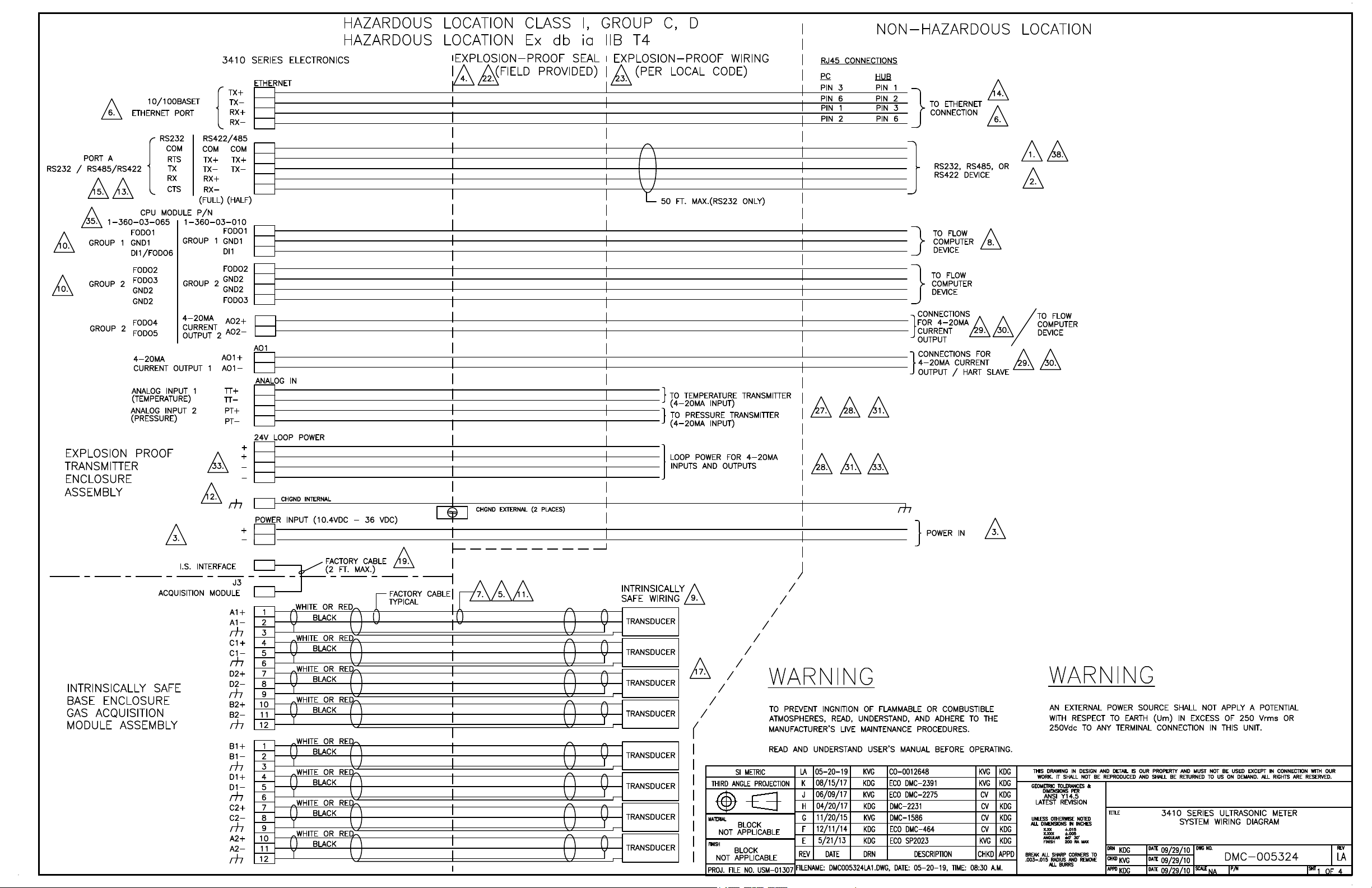
electronics. Refer to the System Wiring Drawing in 3410 Series
engineering drawings.
27. Install a ground wire to the ground lug on the side of the upper
enclosure.
Figure 2-19: Transmitter Electronics Enclosure Ground Wire
28. Attach flex conduit to the conduit ports on the transmitter
electronics enclosure.
Before applying power to the meter, ensure the atmosphere is
proven safe using an intrinsically safe gas detector.
WARNING
EXPLOSION HAZARD
Do not apply power to the meter with the end caps removed unless
you are in a non-hazardous or explosive-free environment.
Failure to comply could result in death, serious injury and possible
equipment damage.
29. Apply the sealing compound to the conduit seal fittings and allow to
set in accordance with manufacturer specifications.
30. Apply electrical power to the system and verify the field connections
are working correctly.
31. Do not install end caps until you configure the meter.
This completes the installation of the hardware associated with the
3410 Series Electronics meter retrofit procedure.
30 Rosemount Gas Ultrasonic 3410 Series Electronics
Page 31

June 2022 Retrofit Instructions
3 Operate
3.1 Configure the 3410 Series Electronics
1. Check all settings and wiring carefully.
2. Set up the Meter Directory, and start initial communication with the
3410 Series electronics.
The basic instructions for setting up the directory and initializing
communications are contained in the following text. Refer to the 3410
Series Gas Ultrasonic Flow Meter Installation Manual for more detailed
instructions. Use MeterLink v1.10 or later to make a connection to the
meter.
3.1.1 Initial communication connection using Ethernet Ethernet initial connection material checklist
The following materials and information are required:
• 3410 Ethernet adapter cable
• Personal computer (PC) configured as follows:
— MeterLink software installed (version 1.10 or later)
— Ethernet LAN adapter
— Configured to automatically obtain IP address (via DHCP)
• Desired 3410 Series meter(s) communication configuration parameters:
— IP address
— Serial communication parameters such as baud rate and Modbus ID
(if desired)
Ethernet initial connection steps
Procedure
1. Power up the 3410 Series meter and wait two minutes for the meter
to startup.
2. Ensure that the Ethernet DHCP server is enabled on the 3410 CPU
Module by setting DHCP switch to the ON position.
3. Plug the Ethernet adapter cable into the meter CPU Module and
connect the RJ45 end into the PC Ethernet connector.
4. Verify the Ethernet connection status by the 3410 CPU Module LINK
LED which should be solid green.
5. Start MeterLink™ on the PC. The Connect to Meter dialog displays.
a) Click the Edit Meter Directory button.
Retrofit Instructions 31
Page 32

Retrofit Instructions June 2022
b) Click the Add button (below the Meter Directory file
operations field). MeterLink inserts the New Meter record in
the last field in the Meter Directory table.
6. Create a new meter directory record with the following parameters:
a) Enter a name for the meter.
b) Select Meter Type as Gas or Liquid as appropriate.
c) Check the Ethernet box and uncheck the Direct and Modem
boxes.
d) Set the Ethernet IP address to 192.168.135.100.
e) Close the Meter Directory window.
7. Use the Meter|Connect menu path and click the Ethernet
connection for the meter record established in the previous step.
MeterLink™ will now connect to the meter using the user-specified
Ethernet settings.
3.1.2 Initial communication connection using RS-232 Serial Communications settings and Field Setup Wizard
RS-232 Serial initial connection material checklist
The following materials and information are required:
• Ultrasonic serial cable.
• Personal computer (PC) with MeterLink™ software version 1.10 (or later)
• Desired 3410 meter(s) communication configuration parameters:
— IP address (if desired)
— Serial communication parameters such as baud rate and Modbus ID
RS-232 Serial initial connection steps
Procedure
1. Power up the 3410 meter and PC.
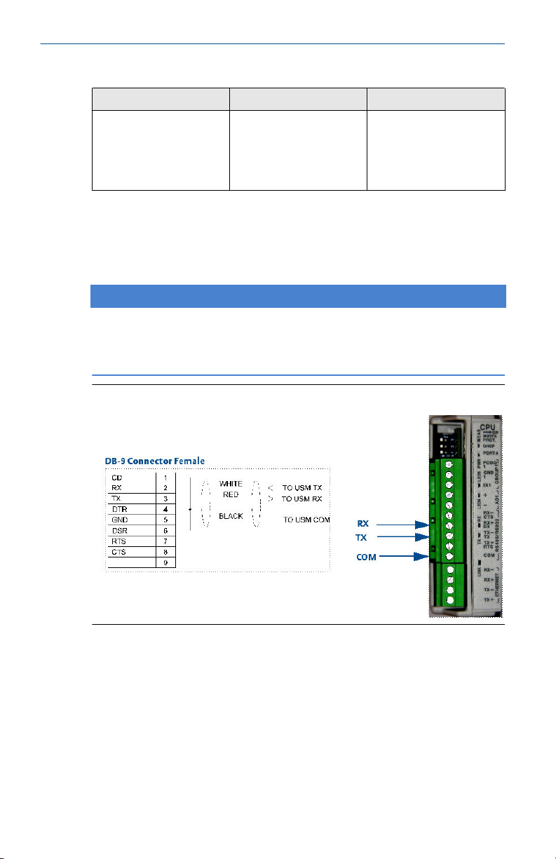
2. Plug the DB-9 end of the cable directly into the PC running
MeterLink. The three wires on the other end of the cable connect to
RX, TX, and COM terminals on the CPU Module. The Digital Out wire
goes to RX, the Digital In wire goes to TX, and the COMMON wire
goes to COM.
32 Rosemount Gas Ultrasonic 3410 Series Electronics
Page 33

June 2022 Retrofit Instructions
Figure 3-1: CPU RS-232 serial connection
Table 3-1: CPU RS-232/RS-485 wire colors
CPU Wire colors
R X Red
T X White
C O M Black
3. Start MeterLink™ on the PC and create a new Meter Directory record
with the following parameters:
Retrofit Instructions 33
Page 34

Retrofit Instructions June 2022
a) Enter a name.
b) Select Meter Type as Gas or Liquid as appropriate.
c) Check the Direct box and uncheck the Modem and Ethernet
boxes.
d) Set the Direct connection properties for Baud Rate of 19200
and Comms Address (Modbus ID) of 32.
4. Use the Meter|Connect menu path and click Direct connection for
the meter record established above. MeterLink™ will now connect to
the meter using the user-specified serial communication settings.
34 Rosemount Gas Ultrasonic 3410 Series Electronics
Page 35

June 2022 Retrofit Instructions
Follow the instructions in LINK HERE to write the converted
configuration file to the meter.
Meter Communications Settings
Procedure
1. Use the Meter|Communications Settings menu path to
access the Communications dialog.
This dialog displays the communications parameters for the 3410
Series electronics and is used to adjust the Baud Rate and Comms
Address (i.e. Modbus ID) for the serial ports.
Figure 3-2: Communications Settings dialog
2. Use the
Driver selection pull-down menu if communication settings
require RS-485
Retrofit Instructions 35
Page 36

Retrofit Instructions June 2022
Figure 3-3: Change driver selection for RS-485 half duplex or full
duplex communication
3.1.3 Write the converted configuration file to the meter
Important
If the Mark III electronics contained keys, the user needs to ensure the same
keys are enabled in the 3410 electronics prior to writing the convereted
configuration. Otherwise, some configuration points may not be able to be
written.
Writing the converted configuration file to the meter
Procedure
1. With communication to the meter established, use the Tools|Edit/
Compare Configuration menu path to access the Edit/Compare
Configuration dialog.
36 Rosemount Gas Ultrasonic 3410 Series Electronics
Page 37

June 2022 Retrofit Instructions
2. Click Open and the Open Configuration File dialog
displays.
Figure 3-4: Edit/Compare Configuration Dialog
a) Select the final configuration file created in Step 2 of
Procedure before removing the Mark III Electronics of this
document (i.e., “Meter Name, MKIII Final Config, 3-4-2005
10-15-02 AM.cfg”).
b) Click Open. The file opens and you returned to the Edit/
Compare Configuration dialog.
Figure 3-5: Open Configuration File Dialog
c) Click Convert (see Figure 3-6). MeterLink™ reads the 3410
configuration from the meter and modifies it with the 3410
configuration.
Retrofit Instructions 37
Page 38

Retrofit Instructions June 2022
Figure 3-6: Edit/Compare Configuration Dialog with
Active Convert Button
If the meter supports HART, check the 2nd variable
parameter setting using the Field Setup Wizard|
Current Outputs dialog. A reminder dialog prompts you
to set this parameter.
Figure 3-7: HART Parameter Settings
For Gas ultrasonic meters, the HART Secondary Variable
options are:
• Uncorrected flow rate
• Corrected flow rate
• Average flow velocity
• Average sound velocity
• Energy flow rate
• Mass flow rate
All data points shown in yellow have been modified from the
3400 configuration.
38 Rosemount Gas Ultrasonic 3410 Series Electronics
Page 39

June 2022 Retrofit Instructions
Figure 3-8: Converted Configuration with Highlighted
Changes
d) Click Write Checked to write the converted configuration to
the meter (see Figure 3-8). If an error occurs, MeterLink™ will
display a message indicating the nature of the problem.
Manually edit the parameter(s) with errors to successfully
complete the download.
e) Click Write Checked again after modifying the parameter(s).
Repeat this until the write occurs with no errors.
f) Save the 3400 Series electronics configuration file to your PC.
g) With the converted configuration still displayed, from the
Edit/Compare Configuration dialog, click the Meter radio
button, located next to the Compare button (see Figure 3-8).
h) Compare the file to verify that this saved configuration
matches the meter configuration. If an error occurs, go back
to the beginning of the Step 2 and try again until no errors are
reported.
3. Use the Meter|Monitor menu path to display the Monitor
window and verify that the meter is operating correctly.
Retrofit Instructions 39
Page 40

Retrofit Instructions June 2022
Figure 3-9: Meter Monitor Dialog
3.1.4 Configure the meter using the Field Setup Wizard Configuring the meter using the Field Setup Wizard
Procedure
1. Use the Meter|Field Setup Wizard menu path to access the
Field Setup Wizard Startup dialog.
a) Verify that all settings (options) are correct (e.g.,
temperature, pressure, meter connections and meter
outputs).
b) In the Meter name field insert a name for the meter (this
name displays on MeterLink™ main window and the
Maintenance logs and Reports files).
c) Ensure the 3410 Series Electronics digital outputs are
configured appropriately. The 3410 Series Electronics also
supports, and may be configured for, the AGA8 Detailed
Method.
40 Rosemount Gas Ultrasonic 3410 Series Electronics
Page 41

June 2022 Retrofit Instructions
Figure 3-10: Field Setup Wizard Startup Dialog
2. Setup the Frequency and Digital Output Sources parameters from
the Field Setup Wizard Frequency/Digital Outputs Sources Page.
Figure 3-11: Field Setup Wizard Frequency and Digital Output
Sources Page
Retrofit Instructions 41
Page 42

Retrofit Instructions June 2022
The meter has user-configurable selections for either a frequency
output or digital status (FODO). Use the pull-down menus to edit
these parameters.
(3) Frequency/Digital Outputs:
• FODO1 (four possible output configurations)
• FODO2(eight possible output configurations)
• FODO3(eight possible output configurations)
Frequency or Digital Outputs (FODO 1) source selections:
• FO1A, DO1A, FO1B, DO1B
Frequency or Digital Outputs (FODO 2) source selections:
• FO1A, DO1A, FO1B, DO1B, FO2A, DO2A, FO2B, DO2B
Frequency or Digital Outputs (FODO 3) source selections:
• FO1A, DO1A, FO1B, DO1B, FO2A, DO2A, FO2B, DO2B
Mode options:
• Open Collector (requires external excitation supply voltage and
pull-up resistor)
• TTL (internally powered by the meter 0-5 VDC signal)
Channel B Phase options:
• Lag forward, Lead reverse (Phase B lags Phase A while reporting
forward flow, leads Phase A while reporting reverse flow)
• Lead forward, Lag reverse (Phase B leads Phase A while reporting
forward flow, lags Phase A while reporting reverse flow)
Phase A and Phase B output (based on flow direction):
• Reverse flow - output only reports flow in the reverse direction.
For frequency outputs, Phase B of the output is 90 degrees out of
phase with Phase A.
• Forward flow - output only reports flow in the forward direction.
For frequency outputs, Phase B of the output is 90 degrees out of
phase with Phase A.
• Absolute - output reports flow in both directions. For frequency
outputs, Phase B of the output is 90 degrees out of phase with
Phase A.
• Bidirectional - output reports flow on Phase A only in the forward
direction and on Phase B only in the reverse direction.
Maximum frequency for the frequency outputs:
42 Rosemount Gas Ultrasonic 3410 Series Electronics
Page 43

June 2022 Retrofit Instructions
• 1000 Hz
• 5000Hz
3. If changes were made in the Field Setup Wizard, choose to save the
configuration when MeterLink™ prompts you after the changes are
written to the meter. Click Finish in the Field Setup Wizard dialog to
write any changes to the meter.
4. You have successfully completed upgrading your3400 electronics to
3410 Series electronics.
5. Save your configuration file for the meter's parameters you just set as
the “As Left Settings”.
Retrofit Instructions 43
Page 44

Retrofit Instructions June 2022
A Mark III RS-232 and RS-485 Serial
communications setup
A.1 Mark III RS-232 Full Duplex
Figure A-1: Port A Settings
Figure A-2: Port B Settings
44 Rosemount Gas Ultrasonic 3410 Series Electronics
Page 45

June 2022 Retrofit Instructions
A.2 Mark III RS-485 Half Duplex
Figure A-3: Port A Settings (Factory Default Switch Settings for Port A)
Figure A-4: Port B Settings
A.3 Mark III Discrete output switch settings
Figure A-5: Group 1 Frequency and Digital Outputs
Retrofit Instructions 45
Page 46

Retrofit Instructions June 2022
Figure A-6: Group 2 Frequency and Digital Outputs
Figure A-7: Series 100 Option Board (If Installed)
46 Rosemount Gas Ultrasonic 3410 Series Electronics
Page 47

June 2022 Retrofit Instructions
A.4 Mark III RS-232 Full Duplex
Figure A-8: Port C Settings
A.5 Mark III RS-485 Half Duplex
Figure A-9: Port C Settings
A.6 Mark III Series 100 option board (if installed)
Figure A-10: Analog Output 1
Retrofit Instructions 47
Page 48

Retrofit Instructions June 2022
Figure A-11: Analog Input 1 (Temperature)
Figure A-12: Analog Input 2 (Pressure)
Figure A-13: Series 100 Plus HART Option Board (If Installed)
48 Rosemount Gas Ultrasonic 3410 Series Electronics
Page 49

June 2022 Retrofit Instructions
A.7 Mark III RS-232 Full Duplex
Figure A-14: Port C Settings
A.8 Mark III RS-485 Half Duplex
Figure A-15: Port C Settings
A.9 Mark III Series 100 plus HART option board (if installed)
Figure A-16: Analog Output 1
Retrofit Instructions 49
Page 50

Retrofit Instructions June 2022
Figure A-17: Analog Output 2 (HART capable)
Figure A-18: Analog Input 1 (Temperature)
Figure A-19: Analog Input 2 (Pressure)
50 Rosemount Gas Ultrasonic 3410 Series Electronics
Page 51

June 2022 Retrofit Instructions
Retrofit Instructions 51
Page 52

Retrofit Instructions June 2022
B Summary table of communications/output
settings
Based on switch position on the 3400 CPU board and Option board if
installed, indicate the appropriate configuration for each communication/
output parameters on the 3400 electronics. Use these parameters to
configure the 3410 Series electronics.
Table B-1: Communications/Output Settings Summary Table
Output
type
Serial
port A
Serial
port B
Serial
port C
Digital
output
1A
Digital
output
1B
Frequen
cy
output
1A
Digital
output
2A
Digital
output
2B
(Check electronics switch settings and circle appropriate box for
each output)
Not
used (if
J6 not
used)
Not
used (if
J7 not
used)
Not
used (if
J16 not
used)
Not
used (if
J4-2 not
used)
Not
used (if
J4-1 not
used)
Not
used (if
J4-1 not
used)
Not
used (if
J5-2 not
used)
Not
used (if
J5-2 not
used)
RS-232 (if S3 is set
to RS232)
RS-232 (if S4 is set
to RS232)
RS-232 (if S10 is
set to RS232)
TTL (if S8-1 is set
to TTL)
TTL (if S8-2 is set
to TTL)
TTL (if S8-3 is set
to TTL)
TTL (if S9-1 is set
to TTL)
TTL (if S9-2 is set
to TTL)
RS-485 Half
Duplex (if S3 is set
to RS-485 and S5-1
is set to Half
RS-485 Half
Duplex (if S4 is set
to RS482 and S5-2
is set to Half)
RS-485 Half
Duplex (if S10 is
set to RS-485)
Open Collector (if
S8-1 is set to OC)
Open Collector (if
S8-2 is set to OC)
Open Collector (if
S8-3 is set to OC)
Open Collector (if
S8-1 is set to OC)
Open Collector (if
S9-2 is set to OC)
RS-485 Full Duplex
(if S3 is set to
RS-485 and S5-1 is
set to Full
RS-485 Full Duplex
(if S4 is set to
RS-485 and S5-2 is
set to Full)
52 Rosemount Gas Ultrasonic 3410 Series Electronics
Page 53

June 2022 Retrofit Instructions
Table B-1: Communications/Output Settings Summary Table
(continued)
Output
type
Frequen
cy
output
1B
Frequen
cy
output
2A
Frequen
cy
output
2B
Analog
input 1
Analog
input 2
Analog
output
1
Analog
output
2 (HART
Capable
)
(Check electronics switch settings and circle appropriate box for
each output)
Not
used (if
J5-1 not
used)
Not
used (if
J5-6 not
used)
Not
used (if
J5-5 not
used)
Not
used (if
J12-1
not
used)
Not
used (if
J12-3
not
used)
Not
used (if
J11 not
used)
Not
used (if
J10 not
used)
TTL (if S8-4 is set
to TTL)
TTL (if S9-3 is set
to TTL)
TTL (If S9-4 is set
to TTL)
Source (if S12 is
set to SRC)
Source (if S13 is
set to SRC)
Source (if S14 is
set to SRC)
Source (if S15 is
set to SRC)
Open Collector (if
S8-4 is set to OC)
Open Collector (if
S9-3 is set to OC)
Open Collector (if
S9-4 is set to OC)
Sink (if S12 is set to
SINK)
Sink (if S13 is set to
SINK)
Sink (if S14 is set to
SINK)
Sink (if S15 is set to
SINK)
Enter the results of the 3400 Summary Table of Communications/output
settings in the table below as a quick reference to setup the 3410 Series
meter configuration parameters.
Table B-2: Communications/Output Settings Summary Table Results
Output type Enter communications and
Serial port A
Retrofit Instructions 53
output settings
Page 54

Retrofit Instructions June 2022
Table B-2: Communications/Output Settings Summary Table Results
(continued)
Output type Enter communications and
Serial port B
Serial port C
Digital output 1A
Digital output 1B
Frequency output 1A
Digital output 2A
Digital output 2B
Frequency output 1B
Frequency output 2A
Frequency output 2B
Analog input 1
Analog input 2
Analog output 1
Analog output 2 (HART Capable)
(1)
(1)
output settings
54 Rosemount Gas Ultrasonic 3410 Series Electronics
Page 55

June 2022 Retrofit Instructions
Retrofit Instructions 55
Page 56

Retrofit Instructions June 2022
C 3410 Communication and Output settings
C.1 3410 Wiring and I/O
Refer to the 3410 Series Ultrasonic Gas Flow Meter Installation Manual for
more wiring details.
Figure C-1: 3410 Upper Electronics with Optional I/O Modules
56 Rosemount Gas Ultrasonic 3410 Series Electronics
Page 57

June 2022 Retrofit Instructions
Figure C-2: CPU Module Labeling and LED Indicators
Table C-1: CPU Module Labeling and LED Functions
CPU Module label or LED Function Switch position indicator
WRITE PROT. Write-protect mode - with
switch in the ON position
(default setting) protects
configuration and
firmware overwrites. To
write configuration
changes or download
firmware to the meter
change the switch to the
OFF position
or LED
Switch position
• ON - (default setting)
enables writeprotection of the
configuration and
firmware
• OFF - enables writing
configuration changes
or downloading
firmware
Retrofit Instructions 57
Page 58

Retrofit Instructions June 2022
Table C-1: CPU Module Labeling and LED Functions (continued)
DHCP Dynamic Host Protocol
Server - enables you to
communicate with a
Rosemount™ Ultrasonic
meter that is not
connected to a network.
When the CPU Module
switch is in the ON
position, the meter is
enabled to act as a DHCP
server for a single DHCP
client connected to the
Ethernet port using a
crossover cable. This
should be used for peer to
peer connections only.
When the connection is
made, select to use the
Meter Name in the meter
instead of the Meter
Directory Name in order to
keep all log files and
configurations separate
from each meter.
PORT A PORT A override - RS-232
serves as an override
during meter
commissioning to
establish communications
and in the event the user
cannot communicate with
the meter due to an
inadvertent
communication
configuration change. The
override period is for two
minutes. Supports:
• auto-detected ASCII
(Start bit 1, Data Bit 7,
Parity Odd/Even, Stop
Bit 1)
• RTU (Start Bit 1, Data
Bit 8, Parity none,
Stop Bit 1).
• Modbus protocols
RS-232 Baud
rate=19,200 Modbus
ID=32
Switch position
• ON - the meter is
enabled to act as a
DHCP server for a
single DHCP client
• OFF - disables the
DHCP server
Switch position
• ON - enables RS-232
PORT A override
• OFF - (default setting)
disables RS-232 PORT
A override
58 Rosemount Gas Ultrasonic 3410 Series Electronics
Page 59

June 2022 Retrofit Instructions
Table C-1: CPU Module Labeling and LED Functions (continued)
MEAS System color indicates
metrology mode
Acquisition mode
Measurement mode
PWR 3.3V Power Indicator Solid Green
LED 4 Not used
LED 5 Not used
RX RX signal (Port A for RS485
or RS232)
communication) receiving
data
TX TX signal (Port A for
RS485; 2-wire or 4-wire) or
RS232 communication)
transmitting data
LINK ETH1Link user Ethernet
connection
LED status
• Red flashing LED
• Solid red the
Acquisition Module is
not communicating
with the CPU Module
• Green flashing LED
Flashing green (when
receiving data)
Flashing green (when
transmitting data)
Solid green
Optional RS-232 Module Wiring
Use the table in MISSING LINK HERE to wire the Optional RS-232 module.
Retrofit Instructions 59
Page 60

Retrofit Instructions June 2022
Figure C-3: Optional RS--232 Module Wiring
Optional RS-485 Module Wiring
Use the table in MISSING LINK HERE to wire the Optional RS-485 module.
Figure C-4: Optional RS-485 Module Wiring
60 Rosemount Gas Ultrasonic 3410 Series Electronics
Page 61

June 2022 Retrofit Instructions
C.2 Ethernet cable to PC communication
The Ethernet port IP address, subnet mask, and gateway address are
software-configurable. In addition, a meter can be configured to act as a
DHCP (Dynamic Host Configuration Protocol) server to assign an IP address
to a PC or laptop running MeterLink. The DHCP server facility is not intended
to act as a general purpose DHCP server for a wider network. To this end, no
user control is provided over the class or range of IP addresses the unit
provides. A standard twisted pair (Cat-5) cable should be used for Ethernet
wiring.
It is strongly recommended that the meter be configured using an
independent (off-network) single host. After configuration of the 3410
Series Gas Ultrasonic Flow Meter, the DHCP option must be turned off if
used on a LAN/WAN.
NOTICE
RESTRICTED ETHERNET AND SERIAL CONNECTIVITY USAGE
Failure to restrict Ethernet and communication access to the 3410 Series Gas
Ultrasonic Flow Meter can result in, among other things, unauthorized
access, system corruption, and/or data loss.
User is responsible for ensuring that physical access and Ethernet or
electronic access to the 3410 Series Gas Ultrasonic Flow Meter is
appropriately controlled and any necessary security precautions are
implemented; such as, establishing a firewall, setting password permissions
and/or implementing security levels.
Retrofit Instructions 61
Page 62

Retrofit Instructions June 2022
Table C-2: Ethernet Communication
Ethernet
Wire color CPU/EXP
White with green Stripe TX+
Solid green TX-
White with orange stripe RX+
Solid orange
Note
Wiring colors for TX+/TXand RX+/RX- can be
switched as ethernet ports
will automatically detect
crossover vs. straight
connection. Connections
shown are straight
through cable.
RX-
Ethernet Communication
Use ethernet cable, to connect the PC to the meter.
A DIN 41612 48-pin connector is the interface from the CPU Module to the
Backplane (male end located on the back of the Backplane Board).
C.3
Input and output connections
The Rosemount 3410 Series Ultrasonic Flow Meter provides the Analog
inputs for pressure and temperature, Analog output 2 and frequency and
digital outputs on the CPU Module lower terminal block.
62 Rosemount Gas Ultrasonic 3410 Series Electronics
Page 63

June 2022 Retrofit Instructions
Figure C-5: CPU Module Lower Terminal Block I/O Connections
A. Frequency/Digital output 2 (FODO 2)
B. Frequency/Digital output 2 (FODO 2) Gnd
C. Frequency/Digital output 2 (FODO 2) Gnd
D. Frequency/Digital output 3 (FODO 3)
E. Analog output 2 + (4-20mA output)
F. Analog output 2 - (4-20mA output)
G. Analog in (Temperature) +
H. Analog in (Temperature) -
I. Analog in (Pressure) +
J. Analog in (Pressure) -
Possible configurations for Frequency and Digital Outputs are shown in the
following figure.
Retrofit Instructions 63
Page 64

Retrofit Instructions June 2022
Figure C-6: Frequency/Digital Output
Output for FODO1 and Digital Output1 (Group 1 on the CPU Module upper
terminal block) share a common ground and have 50V isolation. FODO2 and
FODO3 (Group 2 on the CPU Module lower terminal block) share a common
ground and have 50V isolation. This allows an output to be connected to a
different flow computer. The outputs are opto-isolated from the CPU
Module and have a withstand voltage of at least 500V rms dielectric.
64 Rosemount Gas Ultrasonic 3410 Series Electronics
Page 65

June 2022 Retrofit Instructions
Figure C-7: CPU Module - Frequency/Digital Outputs Common Ground Type 2
A. FODO1 and Digital input1 - shared common ground (Group1)
B. FODO2 and FODO3 - shared common ground (Group2)
Retrofit Instructions 65
Page 66

Retrofit Instructions June 2022
Figure C-8: CPU Module - Frequency/Digital Outputs Common Ground Type 4
A. FODO1 and DI1/FODO6 - shared common ground - Type 4 CPU Module
(Group 1)
B. FODO2, FODO3, FODO4 and FODO5 - shared common ground - Type 4
CPU Module (Group 2)
C.4
66 Rosemount Gas Ultrasonic 3410 Series Electronics
Serial communications
Use a serial cable, to connect to a PC running MeterLink™. The cable is
designed for RS-232 communications which is the serial Port A default
configuration (see 3410 Series engineering drawings Systems Wiring
Diagram, Drawing DMC - 005324).
The DB-9 end of the cable plugs directly into the PC running MeterLink. The
three wires on the other end of the cable connect to the CPU Module
RS-485/RS-232 terminals. The RED wire goes to RX, the WHITE wire goes to
TX, and the BLACK wire goes to COM (see Table 3-5 for Port A wiring).
RS-485, 2-wire connection on Port A, uses TX+ and TX- on the CPU Module
and has a ground wire.
When Belden wire No. 9940 or equivalent is used, the maximum cable
length for RS-232 communications at 9600 bps is 88.3 meters (250 ft.) and
the maximum cable length for RS-485 communication at 57600 bps is 600
meters (1970 ft.).
Page 67

June 2022 Retrofit Instructions
Port A supports a special override mode which forces the port to use known
communication values (19200 baud, address 32, RS-232). Note that the
protocol is auto-detected. This mode is expected to be used during meter
commissioning (to establish initial communication) and in the event that the
user cannot communicate with the meter (possibly due to an inadvertent
communication configuration change). Alternately, when using MeterLink
with an Ethernet port, use Ethernet cable, to connect the PC.
Table C-3: Serial Port Parameters
Port/communication Description Common features
• Port A (Standard)
• RS-232
• RS-485 Half Duplex
• RS-485 ( 2-wire
communication on
(1)
Port A.)
• Typically used for
general
communications with
a flow computer, RTU
(Modbus slave) and
radios.
• RS-485 - 2-wire (Half
Duplex) connected to
TX + and TX -
• Special override mode
to force port
configuration to
known settings.
• Supports RTS/CTS
handshaking with
software-configurable
RTS on/off delay
times.
• Factory default is
RS-232, Address 32,
19200 baud.
• Communications via
MeterLink using
RS-232 or RS-485 Full
Duplex
• Software configurable
Modbus Address
(1-247)
• Auto-detects TCP/IP
and ASCII or RTU
Protocol
• ASCII Protocol:
— Start Bits = 1, Data
Bits = 7
(2)
— Parity: odd or
even 1, Stop Bits =
(3)
1
— Baud Rates: 1200,
2400, 9600,
19200, 38400,
57600, 115000
bps
—
• RTU Protocol: Start
Bits = 1, Data Bits =
(4)
8
— Parity: none, Stop
Bits = 1
(5)
— Baud Rates: 1200,
2400, 9600,
19200, 38400,
57600, 115000
bps
Retrofit Instructions 67
Page 68
Retrofit Instructions June 2022
Table C-3: Serial Port Parameters (continued)
Port/communication Description Common features
Ethernet Preferred port for
diagnostic
communication via
MeterLink
10 Mbps/100 Mbps
(1) RS-485 2-wire connections use TX+ and TX - on the CPU Module
(2) Denotes auto-detected protocols
(3) Denotes auto-detected protocols
(4) Denotes auto-detected protocols
(5) Denotes auto-detected protocols
Modbus TCP/IP, Modbus
TCP
NOTICE
If not using Ethernet, a full duplex serial connection is necessary for
MeterLink to communicate with a Rosemount 3410 Series Ultrasonic Flow
Meter.
Figure C-9: PC to Meter Serial Connection Wiring
C.5 Analog input settings
The Rosemount 3410 Series Ultrasonic Flow Meter has the capability to
sample analog temperature (Analog Input 1) and pressure (Analog Input 2)
with 4-20 mA signals. These analog input signals are configured to sink. The
two independent analog input circuits are configured for conventional 4-20
mA service. Also, 24VDC isolated power supply connection is provided for an
external power source. Refer to the System Wiring Diagram in 3410 Series
engineering drawings.
68 Rosemount Gas Ultrasonic 3410 Series Electronics
Page 69

June 2022 Retrofit Instructions
C.6 Analog output settings
The Rosemount 3410 Series Ultrasonic Flow Meter provides two 4-20 mA
analog output signals that are software configurable for either sink or source
current. Refer to the System Wiring Diagram in 3410 Series engineering
drawings.
Full HART® functionality is provided so that any commercially available HART
transmitter which meets the specifications of the HART Communications
Foundation can be connected to a Rosemount 3410 Series Ultrasonic Flow
Meter.
C.7 Digital Input
The Rosemount 3410 Series Ultrasonic Flow Meter provides one digital input
that can be used as a general purpose input. The digital input must be
configured via the MeterLink™ Tools|Edit/Compare
Configuration screen.
C.8 External power source connection and fuse
Located on the CPU Module are connections for a user-provided external
power source, a 2 Amp fuse and a 24V loop power connection for ultrasonic
meter analog outputs, temperature transmitter or pressure transmitter
devices. The current is limited to 88mA.
Retrofit Instructions 69
Page 70

Retrofit Instructions June 2022
Figure C-10: CPU Module Power Source Connections
A. 24V Loop power
B. Power in connector (main power source)
C. 2 Amp fuse (used for main power input)
70 Rosemount Gas Ultrasonic 3410 Series Electronics
Page 71

June 2022 Retrofit Instructions
Retrofit Instructions 71
Page 72

Retrofit Instructions June 2022
D 3410 Series engineering drawings
DMC-005324 3410 Series Ultrasonic Meter System
Wiring Diagram
72 Rosemount Gas Ultrasonic 3410 Series Electronics
Page 73
Page 74

≥
≥
≥
≥
≥
≥
Page 75

WARNING
WARNING
3/4 NPT
3/4 NPT
US
C
LISTED
90Y1
·
·
·
·
TELEMETERING
EQUIPMENT
FOR HAZ. LOC.
Page 76

≥
≥
≥
≥
≥
≥
≥
≥
≥
≥
≥
≥
Page 77

June 2022 Retrofit Instructions
Retrofit Instructions 75
Page 78

* 00825-0300-3240 *
Retrofit Instructions
00825-0300-3240 , Rev. AA
June 2022
For more information:
©
2022 Emerson. All rights reserved.
Emerson Terms and Conditions of Sale are
available upon request. The Emerson logo
is a trademark and service mark of
Emerson Electric Co. Rosemount is a mark
of one of the Emerson family of
companies. All other marks are the
property of their respective owners.
Emerson.com
 Loading...